

Page 1
U-115N/L Middleweight Folding Easel
ASSEMBLY INSTRUCTIONS
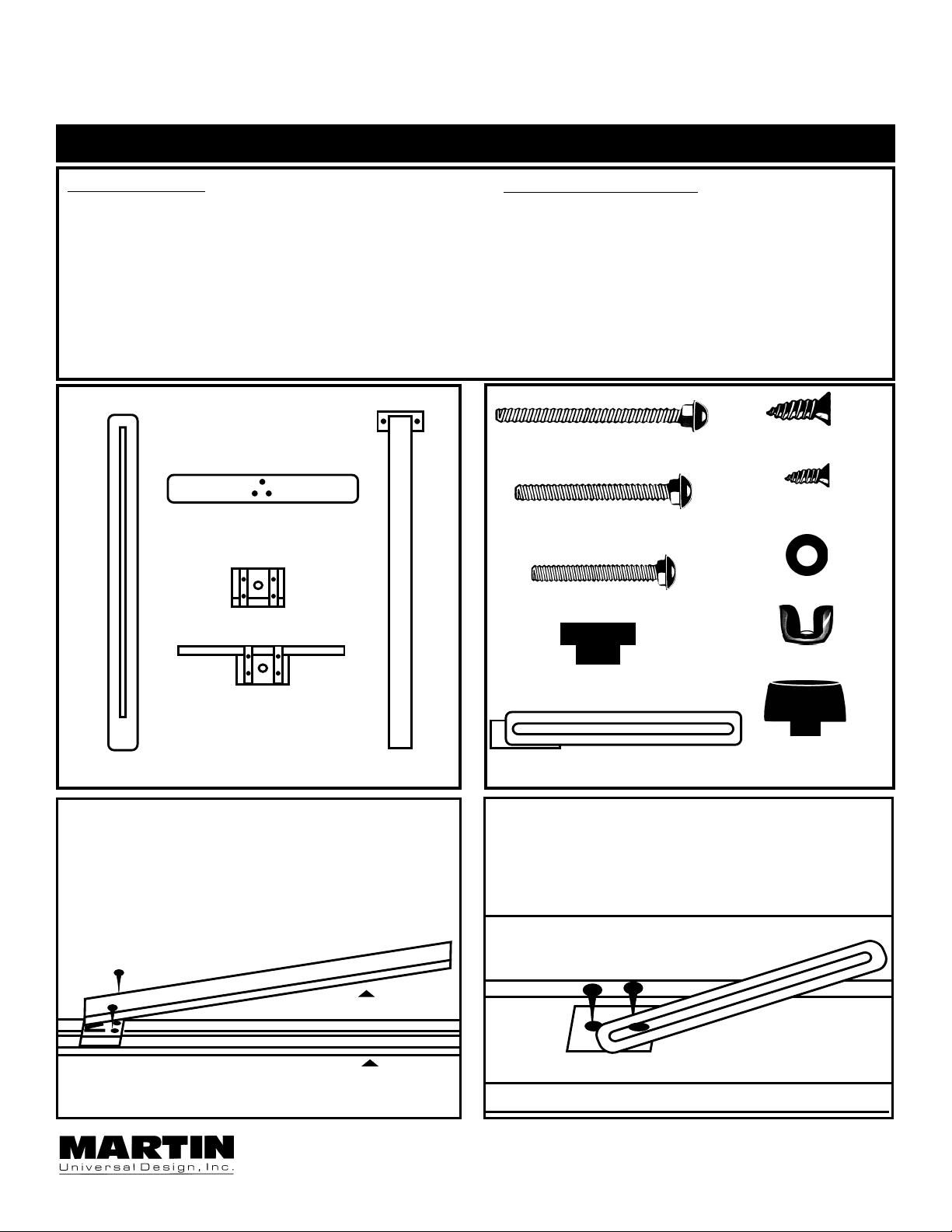
MAKE SURE CARTON CONTAINS THE FOLLOWING PARTS
WOOD PARTS
1 ea. .......Channelled Center Column
1 ea. .......Rear Spike Leg
........with attached wooden block
1 ea. .......Base Foot
1 ea. .......Upper Canvas Support
1 ea. .......Lower Canvas Support
Layout all wood parts
on hard flat floor
with all holes facing up.
Base Foot
Upper Canvas Support
HARDWARE PARTS
1 ea. .......3” Bolts [A]
2 ea. .......2½” Bolts [B]
3 ea. .......2” Bolts [C]
2 ea. .......1” Wood Screws [D]
2 ea. .......½” Wood Screws [E]
3 ea. .......Washers [F]
3 ea. .......Wingnuts [G]
2 ea. .......Plastic Channel Guides [H]
2 ea. .......Plastic Knobs [I]
1 ea. .......Metal Stay [J]
[A] 1ea. - 3” Bolt
[B] 2ea. - 2½” Bolts
[C] 3ea. -2” Bolts
[D] 2ea.
1” Wood Screws
[E] 2ea.
½” Wood Screws
[F] 3 ea. - Washers
Lower Canvas Support
Channelled
Center Column
STEP 1. Before Attaching Rear Spike Leg.
MAKE SURE rear leg is in this position before
attaching to Channelled Center Column.
Continue by aligning screw holes and proceed
by screwing in 2 ea. 1” wood screws [D] into
wood block and then into upper cross member.
+
+
Rear Spike Leg
Channelled Center Column
Rear spike leg w/
woodedn block
FIG 1
[G] 3 ea. - Wingnuts
2ea.
[H] Plastic Channel Guide
[J] 1ea. - Metal Stay
Plastic Knobs
STEP 2. Attaching Metal Stay [J] to Easel
MAKE SURE Positioning of metal stay [J] is
CORRECT as shown below in FIG. 2.
Align holes in metal stay with pre-tapped holes in
center column. Attach using 2 ea. 1/2” wood
screws [E] and tighten.
+
+
Metal Stay in Correct Position
[I] 2ea.
Channel in
center column
FIG 2
Martin Universal Design, Inc. • 4444 Lawton Avenue, Detroit, MI 48150 USA
T el:(313)895-0700 • Fax:(313)895-0709 • E-mail:Mudmfwdet@aol.com
Page 2
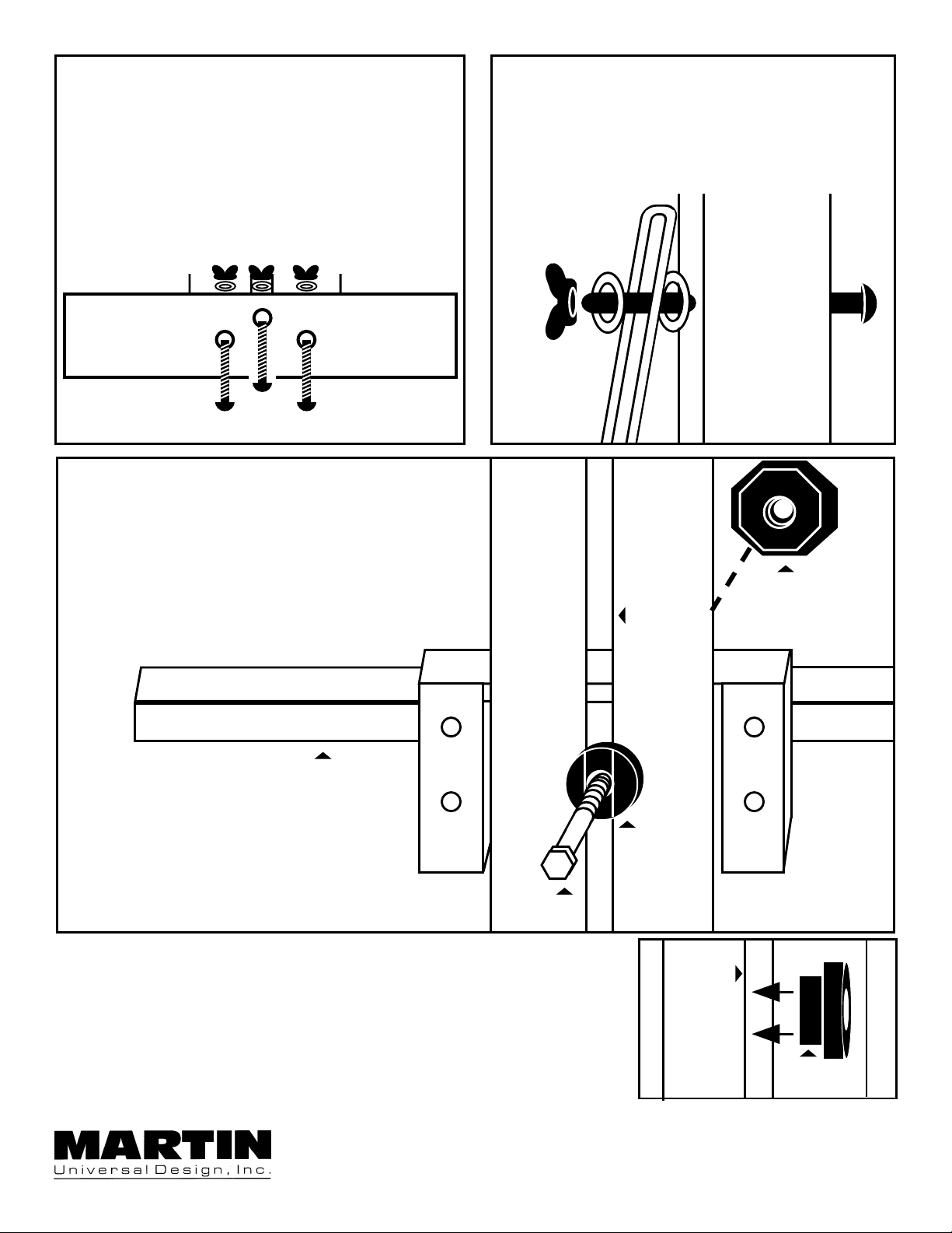
STEP 3. Attaching Base Foot.
Lay Channelled Center column and Rear Leg
assembly down on flat floor with Channelled
Center Column facing up.Take the Base Foot
and align the holes in it with the holes on the
Channelled Center Column.Using 3 ea. 2” Bolts
[C], washers [F] and wingnuts [G], attach
basefoot to channelled center column.
SEE FIG 3.
STEP 4. Attaching rear support leg to Metal Stay [J].
Take 3” bolt [A] and insert through hole
provided in side of rear support leg. Proceed
by adding a washer [F], then insert bolt
through channel of metal stay [J], add another
washer [G] and then wingnut [G]. Tighten wing
nut at desired angle. SEE FIG 4.
STEP 5. Attaching Lower Canvas Support
Hold lower canvas support to front of channelled
center column and insert plastic channel guide [H]
through rear of channelled center column.
SEE FIG 5.
Then insert 2½” (½ threaded)bolt through plastic
channel guide [H] and screw plastic knob [I] onto
bolt [B] located on front of lower canvas support.
Tighten knob at desired height of canvas support.
SEE FIG 5.
Rear View of Lower
Canvas Support
STEP 7. Attaching Upper Canvas Support
REPEAT above step for
upper canvas support.SEE FIG 6.
FIG 3
FIG 4
[I] Plastic Knob
Channelled
Center
Column
+
+
[H] Plastic
Channel
Guide
[B] Bolt for
Plastic Channel
Guide
+
+
FIG 5
STEP 8. RECHECK all screws and bolts to make sure they are all
tightened.
STEP 9. Adjust rear support leg, upper & lower canvas supports to
desired heights.
STEP 10. Your easel is now ready for your painting enjoyment, ENJOY!
Martin Universal Design, Inc. • 4444 Lawton Avenue, Detroit, MI 48150 USA
Tel:(313)895-0700 • Fax:(313)895-0709 • E-mail:Mudmfwdet@aol.com
Channelled
Center
Column
FIG 6
[H] Plastic
Channel
Guide
 Loading...