

Page 1
Manchester Split-top Table Assembly Instructions
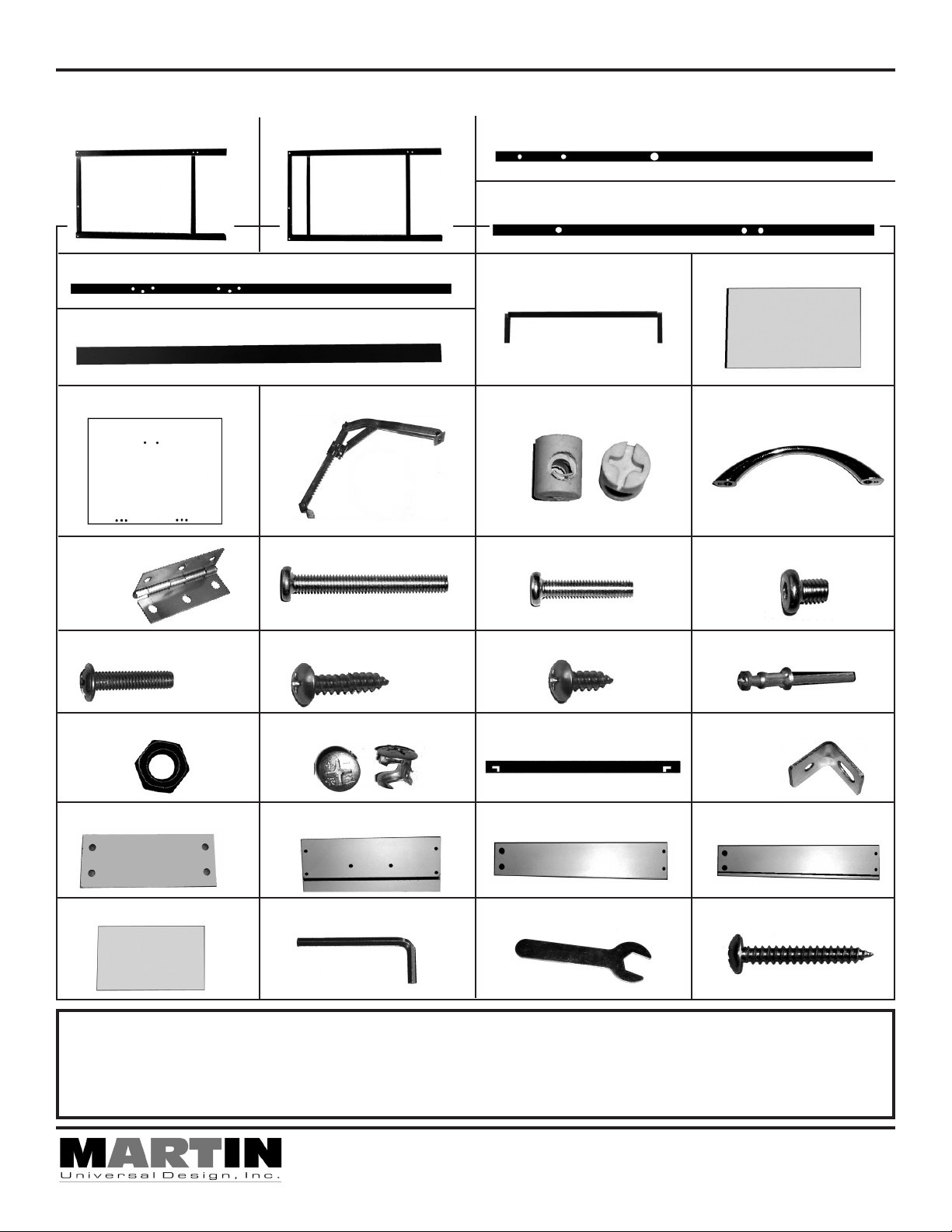
Parts List
Part A - 1 piece Part B - 1 piece Part C - 1 piece
Part D - 1 piece
Part E - 1 piece
Part F - 1 piece
Part I - 1 piece
Part M
- 2 pieces
Part Q - 2 pieces
Part J - 1 piece
Part N - 10 pieces
Part R - 3 pieces
4x18mm 4x12mm4x30mm
Part G - 1 piece
Part K - 4 pieces
Part O - 4 pieces
6x30mm6x50mm 6x8mm
Part S - 14 pieces
Part H - 1 piece
Part L - 1 piece
Part P - 3 pieces
Part T- 4 pieces
Part U - 2 pieces
Part Y - 1 piece
Part B1 - 1 piece
If you have difficulty assembling your Manchester Table or need customer service assistance.
Please call: Martin Universal Design, Inc. Customer Service Hot Line at 1-313-895-0700.
If you need additional parts, it is not necessary to contact your dealer, our Customer Service Rep.
Part V - 4 pieces
Part Z - 1 piece
Part C1 - 1 piece
IMPORTANT
will forward them to you immediately.
4444 Lawton Avenue, Detroit, MI 48208 USA • Tel:(313)895-0700/Fax:(313)895-0709
Email: Custservmud@aol.com • visit us at www.MartinUniversalDesign.com
Part W - 1 piece
Part A1R - 1 piece
Part D1 - 1 piece
Part X- 1 piece
Part A1L- 1 piece
Part E1- 4 pieces
4x35mm
Pg. 1
May 08- RPI
Page 2
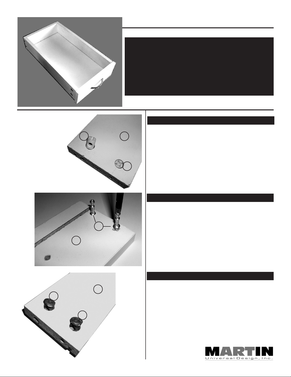
Manchester DRAWER Assembly
PLEASE NOTE:
Assemble the Drawer FIRST before assembling the base.
Once assembled, set drawer to side.
Assembled drawer to be used later
during assembly of table.
FIG A
Z
K
STEP 1] Assemble Drawer
Begin by taking the back panel of drawer (Part Y) and
Y
inserting 1 plastic T-nut (part K) into each hole, making
sure the hole in the T-nut is lined up with the hole in the
edge of the back panel. See FIG A.
K
STEP 2] Assemble Drawer, cont’d.
Take the Drawer Front (Part Z) and insert the 4
Threaded Connector Pins (Part T). Use Phillips
Screwdriver to secure Threaded Connector Pins
T
into Drawer front.
See FIG B.
May 08- RPI
Pg.2
V
V
A1L
FIG C
FIG B
STEP 3] Assemble Drawer, cont’d
Take the Sides of the Drawer (Parts A1R & A1L) and
insert the 2 T-nuts into the holes found on each side
panel, making sure the holes of the T-nuts line up with
the holes on the outer edge of the drawer sides.
See FIG C.
Page 3
Manchester DRAWER Assembly
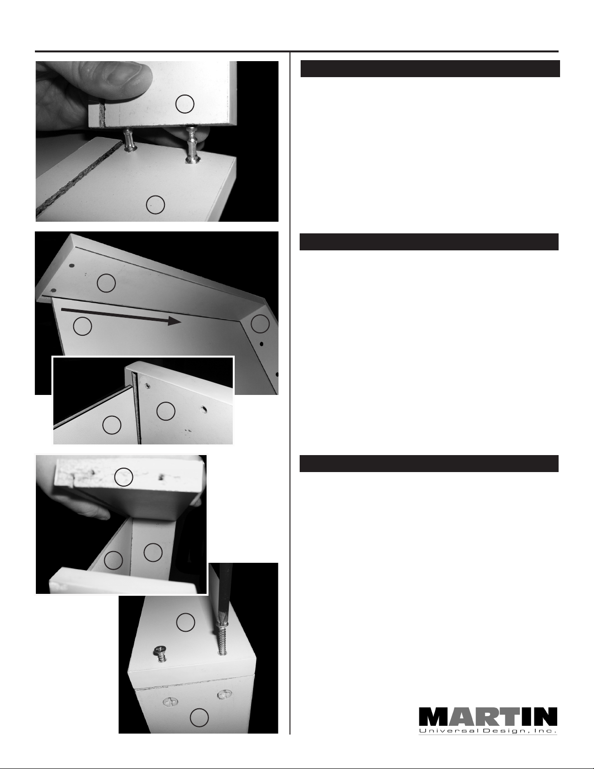
STEP 4] Assemble Drawer, cont’d
Attach sides of drawers (Parts A1L & A1R) to the Drawer
A1L
front (Part Z) by inserting Threaded Connection Pins
into the holes on the outside edge of the Drawers sides
(Parts A1L & A1R).
PLEASE NOTE: The Grooves in each side must be
lined up with each other to allow the drawer bottom
to be installed.
B1
A1R
B1
To secure, tighten the T-nuts found on the outer side of
the drawer sides. Turn the T-nuts until tight. See FIG D
STEP 5] Inserting Drawer Bottom
Slide the Drawer bottom (Part B1) into the grooves on the
sides of the drawers and into the front of the drawer.
NOTE: Brown side of drawer bottom is the bottom of
the drawer. White side up for inside drawer
bottom.
See FIG E
K
Z
FIG D
FIG E
Z
A1R
STEP 6] Completing Drawer Assembly
Z
Complete Drawer Assembly by attaching the Drawer
back (Part Y) to the drawer by inserting the drawer bottom
into the groove on the drawer back. See FIG F
FIG F
May 08- RPI
Pg. 3
B1
A1R
To secure Drawer Assembly, insert 2 each 4x35mm
screws (Part E1) into the drawer sides and tighten with
phillips screwdriver, as shown in FIG G
FIG G
Z
A1L
Page 4
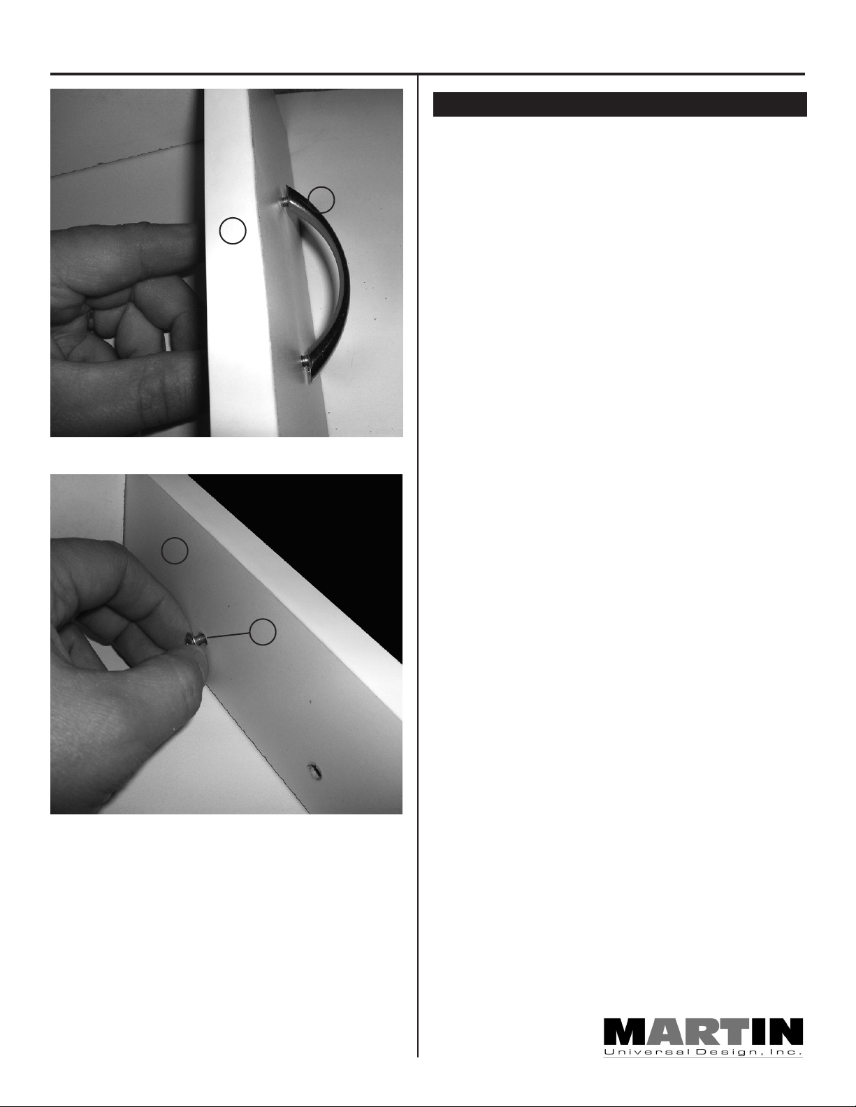
Manchester DRAWER Assembly
STEP 7] Attaching Drawer Handle
Attach drawer handle (Part L) to drawer, using 2 each
4x18mm screws (Part Q). See FIG H
Insert screws (Part Q) through inside of drawer into ap
L
propriate holes and tighten with phillips screwdriver. Hold
onto drawer handle while securing screws. See FIG I
-
Z
Go back and double check all screws are tight on all
sections of drawer.
Set Drawer aside and begin table assembly.
FIG H
FIG I
Z
Q
May 08- RPI
Pg. 4
Page 5

Manchester Split-top Table Assembly Instructions
N
N
N
A
A
A
D
C
D
FIG 1
FIG 2
STEP 1] Assembly Base of Table
Begin by assembling the base by taking the left side
(part A) and attaching the three cross supports (part
C, D & E) using 1 each 6x50mm hex bolts (part N) into
each hole found on the outside side edge of Part A and
lining that hole up with the hole in the end of each cross
support. Tighten hex bolt with Allen Wrench (part C1).
SEE FIG 1,2 & 3
PLEASE NOTE: The Black square caps as shown in
FIG 1 indicate the top side of Parts A & B
PLEASE NOTE: DO NOT OVERTIGHTEN HEX BOLT
to cause frame to bend.
Attach cross support (part D) to Side A
FIG 2.
A
D
E
C
FIG 3
E
Attach cross support (part E) to Side A
FIG 3.
STEP 2] Assembly Base of Table, cont’d
This is what your partial assembled base should now
look like. See FIG 4.
May 08- RPI
Pg. 5
FIG 4
Page 6

Manchester Split-top Table Assembly Instructions
STEP 3] Assembly Base of Table, cont’d
FIG 5
D
B
C
B
N
N
FIG 6
Repeat with right side (part B) by attaching the other end
of the three cross supports (part C, D & E) using 1 each
6x50mm hex bolts (part N) into each hole found on the
outside side edge of Part A and lining that hole up with
the hole in the end of each cross support. Tighten hex
bolt with Allen Wrench (part C1). SEE FIG 5,6 & 7
PLEASE NOTE: The Black square caps as shown
in FIG 1 indicate the top side of Parts A & B
PLEASE NOTE: DO NOT OVERTIGHTEN HEX BOLT
to cause frame to bend.
Attach cross support (part D) to Side A
FIG 6.
E
B
N
FIG 7
Attach cross support (part E) to Side A
FIG 7.
STEP 4] Assembly Base of Table, cont’d
This is what your partial assembled base should now
look like. See FIG 8.
May 08- RPI
Pg. 6
FIG 8
Page 7

FIG 9
Manchester Split-top Table Assembly Instructions
STEP 5] Attach Lower Cross support
Attach lower wider Cross Support (part F) to lower
N
F
B
portion of base by lining up the two holes on each end
of Part A & B with the two holes found in each end of
Part F. Secure by using two each 6x50mm Hex Bolts
in each end.
SEE FIG 9.
PLEASE NOTE: DO NOT OVERTIGHTEN HEX BOLT
to cause frame to bend.
STEP 6] Assembly Base of Table, cont’d
A
Front of Table
J
If you assembled the base correctly, the assembled
base should now look like FIG 10.
B
F
STEP 7] Attach Tilt Mechanism to Base
FIG 10
E
FIG 11
This step involves attaching the Tilt Mechanism (Part
J) to the Base. Find the 2 holes on top side of cross
support (part D). Secure Tilt Mechanism to this cross
support using 2 each 6x30mm Hex Bolts (Part O) & 2
each Hex Nuts (Part U). The Nuts are to be positioned
on the underside of cross support D. Use wrench (part
D1) to hold nuts while tightening down Hex bolts. See
FIG 11 & FIG 11B for proper positioning.
PLEASE NOTE: The elbow of the Tilt Mechanism is
to be pointed to the rear of the table Base.
See below for Photo that shows this.
Rear of Table
May 08- RPI
Pg. 7
D
D
This is the underside
of Part D
Elbow of the Tilt Mechanism
faces the rear of the table
J
FIG 11B
Page 8

FIG 12
Manchester Split-top Table Assembly Instructions
STEP 8] Attach Drawer support guide
Attach Drawer support guide (Part G) to base cross
E
G
Drawer
Support
Guide
M
E
supports (part C & E) using 2 each 6x30mm Hex bolts.
Tighten with Allen Wrench. See FIG 12.
PLEASE NOTE: Make sure the Drawer Support
guide is facing the right as in FIG 12.
STEP 9] Attach Hinges to base
Attach 2 Hinges (Part M) to front edge Cross support
(Part E) by lining up holes in hinge and holes in cross
support E using 3 each 4x12mm screws (Part S) per
hinge. Tighten with phillips screwdriver. SEE FIG 13.
Front edge of base
FIG 13
Hinges
need to be
attached as
shown at
right.
Line up holes in
hinge with holes
in top
PLEASE NOTE: Make sure that the Hinge is
positioned as in FIG 13B
G
E
FIG 13B
STEP 10] Attaching Base to Top
Align holes in hinges to holes in top and align holes in
tilt mechanism (Part J) to threaded holes in top.
See FIG 14
J
Line up holes in
tilt mechanism
and T-nuts in top
May 08- RPI
Pg. 8
FIG 14
Page 9

Manchester Split-top Table Assembly Instructions
STEP 11] Attach Tilt Mechanism to Top
After lining up holes, attach tilt mechanism (Part J) to
J
FIG 15
top with 2 each 6x8mm Hex Bolts (Part P). Tighten with
Allen Wrench. See FIG 15.
STEP 12] Attach Hinges to Top
Attach the 2 Hinges (Part M) to the top by using 3 each
4x12mm screws (Part S) per hinge. Tighten with
phillips screwdriver.
See FIG 16.
M
FIG 16
WARNING:
Turn table upright with TWO PEOPLE - DO NOT ATTEMPT to turn assembled table
onto its legs with only one person. Then continue with assembly
STEP 13] Attach Drawer Stop
PLEASE NOTE:
Before attaching Drawer Stop (Part X), the Drawer
must be installed FIRST!
To do so, slide drawer onto drawer glides
See FIG 17.
May 08- RPI
Pg. 9
FIG 17
Page 10

Manchester Split-top Table Assembly Instructions
STEP 14] Attaching Drawer Stop, cont’d
After sliding Drawer into table, you need to install the
drawer stop (Part X). This can be a bit tricky.
You need to position the Drawer Stop (Part X) as shown
in FIG 18 and FIG 18b, then from underneath, secure
the drawer stop with a 6x8mm Hex Bolt (Part P). Tighten
X
P
FIG 18
with the allen wrench.
D
X
FIG 18b
P
If installed correctly, the Drawer will not be able to be
pulled all the way out of the table.
See FIG 19.
May 08- RPI
Pg. 10
FIG 19
Page 11

Manchester Split-top Table Assembly Instructions
WARNING:
To Install the SIDE SHELF, the Table must be turned back over onto its Table Top.
Use 2 People to turn Table over onto the Table Top, making sure it is placed on a
protected surface like a carpeted floor.
STEP 15] Attaching Side Shelf
Table Top
Drawer Bottom
Table Top
NOTE: The photo at the left show the table laying
top down on the carpeted floor and standing above
the table looking downward.
Slightly lift the table up and slide the side shelf (Part
H) underneath the drawer section, making sure to line
up the Side shelf so that the edges are flush and even
with the edge of the table top. See FIG 20
Continue with attachment of side shelf
on next page.
May 08- RPI
Pg. 11
Drawer
Bottom
Side Shelf
FIG 20
Line up the Side shelf so that
the edge of the shelf is flush
with the edge of the table top.
Indicated by the white line.
Page 12

Manchester Split-top Table Assembly Instructions
FIG 21
Secure with
STEP 16] Attaching Side Shelf
Once Side Shelf is positioned correctly, secure shelf
using 3 wood 4x30mm screws (Part R) in the holes
indicated in FIG 21. Use a Phillips Screwdriver to
secure.
DO NOT OVER TIGHTEN - This will cause the
screws to be loose.
screws in the
indicated holes
WARNING:
Your Table needs to be turned back onto its legs. Use 2 people to carefully turn the
table back over onto its legs.
STEP 17] Attaching Pencil Ledge
W
FIG 22
Side view of pencil
ledge after properly
installed on table top
Proper Assembled Table should now look like
Photo at Right.
To Tilt Table Top, lift on back edge of table top,
from flat position and lift until desired position.
Attach Pencil Ledge (Part W) to the front edge of table
top, using 2 each 4x12mm screws (Part S) as shown
in FIG 22.
4444 Lawton Avenue, Detroit, MI 48208 USA • Tel:(313)895-0700/Fax:(313)895-0709
Email: Custservmud@aol.com • visit us at www.MartinUniversalDesign.com
Pg. 12
May 08- RPI
 Loading...