

Page 1
CAMBRIDGE I & II PRINT RACK
Assembly Instructions - Page 1
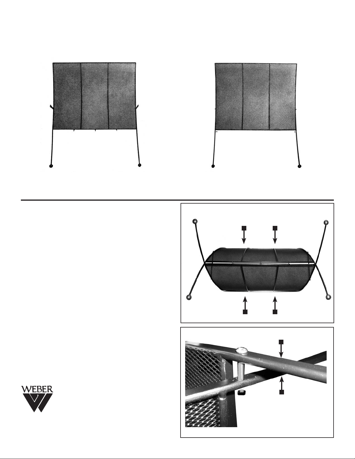
Part A
This side has the hinges attached
ASSEMBLY INSTRUCTIONS ARE THE SAME
FOR BOTH MODEL I & MODEL II
STEP 1.
Begin by removing any protective packaging
found wrapped around the print rack parts and
discard.
Remove the [2] Screws and nuts from Part B.
STEP 2.
Place Part B in-between the legs of Part A as
shown in FIG 1 at right.
STEP 3.
Secure by inserting the screw through the side
outer hole of Part A and through the hole in the
side of Part B. Secure with nut. NOTE: Hold Nut
in place with wrench while tightening screw with
screwdriver. See FIG 2.
Part B
This side has the [2] screws & nuts attached
FIG 1.
Part B
Part A
Screw
Part A
Martin/F. Weber Co. • 4444 Lawton Avenue, Detroit, MI 48208 USA
Tel:(313)895-0700 • Fax:(313)895-0709 • E-mail:Custservmud@aol.com
www.MartinUniversalDesign.com • www.weberart.com • Made in China
Created OCT07 RPI
Nut
Part B
FIG 2.
Page 1
Page 2
CAMBRIDGE I & II PRINT RACK
Assembly Instructions - Page 2
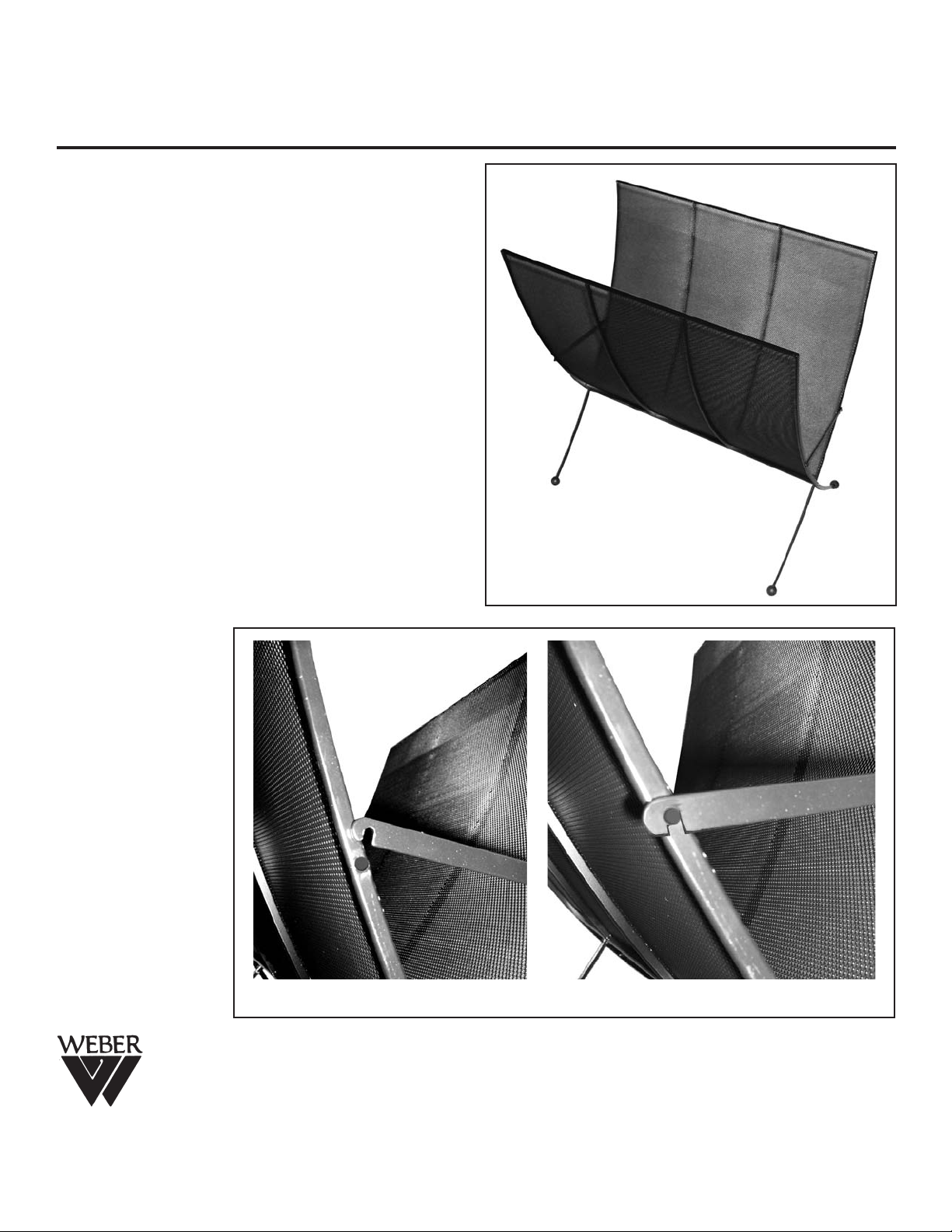
STEP 4.
Once Screws and nuts are secure, turn the
Cambridge Print Rack over onto its rubber balled
feet. See FIG 3.
STEP 5.
Secure Side Hinges by clasping down the notch
over the rivet on the side of Part B.
See FIG 4 & FIG 5.
Your Cambridge Print Rack
is now ready to use.
FIG 3
Martin/F. Weber Co. • 4444 Lawton Avenue, Detroit, MI 48208 USA
Tel:(313)895-0700 • Fax:(313)895-0709 • E-mail:Custservmud@aol.com
www.MartinUniversalDesign.com • www.weberart.com • Made in China
Created OCT07 RPI
FIG 5FIG 4
Page 2
 Loading...