

Page 1
Print Rack Assembly Instructions
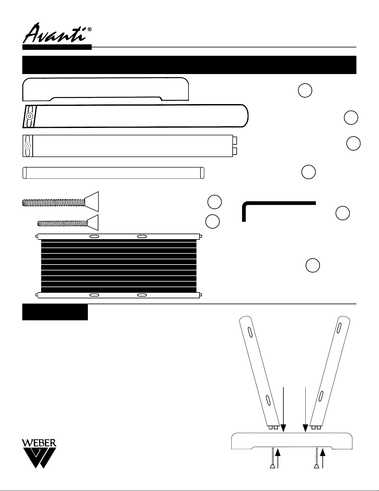
Carton Contains
- [2] Each Base Feet A
- [4] Angled Legs B
- [2] Cross Members C
- [4] Flat Spindles D
- [4] 2-3/8” Hex Bolts E
- [1] Hex Wrench G
- [8] 1-3/4” Hex Bolts F
Assembly:
Step 1:
Empty contents of carton. Make sure all parts listed above are
included. If you are missing any part, please call our Customer
Service Dept at: (313)895-0700.
Step2:
Begin by attaching each angled leg (B) to base foot (A). Make
sure oval cut-outs are facing inward.
Push wood into cutout on base and secure by using [1] 2-3/8”
Hex Bolt (F) through bottom of base foot (A). DO NOT Tighten
completely. Repeat with remaining 3 Angled Legs (B).
SEE FIG. 1
- [1] Material Shelf H
FIG. 1
(B) (B)
(A)
Martin/F. Weber Co.
4444 Lawton Avenue, Detroit, MI 48208 USA
(E)
Page 2
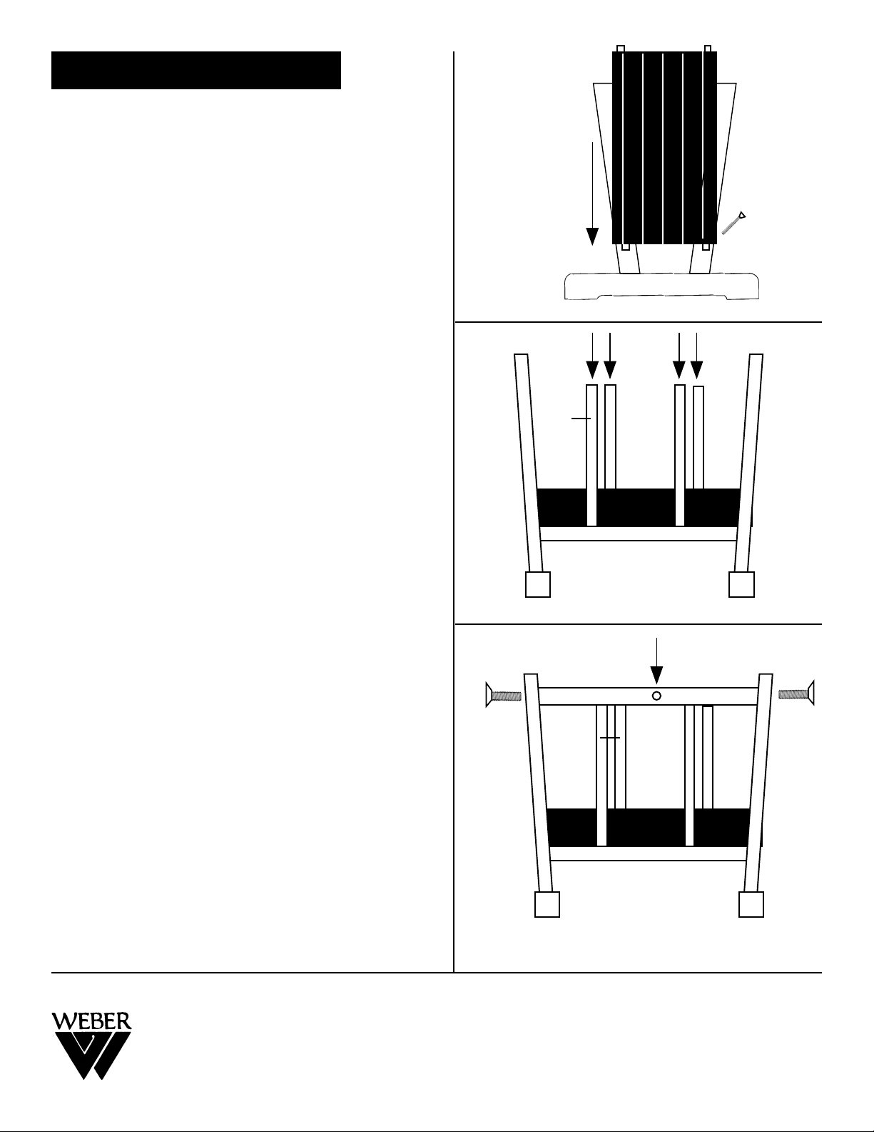
Assembly continued:
FIG. 2
Step 3:
Take the 1 of the leg assemblies and lay it down flat
on a flat surface. Making sure the oval slots are
facing upward. Attach the Material Shelf (H) by
inserting one end of it into the lower slots of the leg
assembly. You may need to pound the tray down
into the slots by using a rubber mallet. PLEASE
NOTE: Legs may need to be slight adjustment to fit.
Secure by inserting (2) 1-3/4” Hex Nuts (F) into the
opposite side holes. Finger Tighten. SEE FIG 2.
Step 4:
Attach other leg assembly by inserting end of material shelf (H) into lower oval slots of leg assembly.
Secure by inserting (2) 1-3/4” Hex Nuts into the
opposite side holes. Finger Tighten.
Step 5:
Stand rack assembly upright onto its base legs.
Insert all 4 flat spindles (D) into their respective slot
holes on edge of material shelf. You may have to
work the spindle in a back-in-forth motion while
applying pressure to get the spindle in the slot hole.
This tightness is for durability. SEE FIG. 3
(B)
(H)
(F)
(A)
(D)
(B)
(H)
Step 6:
Attach (2) Cross Members (C) by inserting one end
of cross member into one side of leg assembly, then
proceed to move across to the flat spindles (D) and
then to the other end of leg assembly. By following
this order, the cross member is easier to attach.
Make certain logo on Cross Member (C) is on outside edge. Secure by inserting a 1-3/4” Hex Bolt into
each end of leg assembly. Tighten. Repeat with
other side. SEE FIG. 4
Step 7:
Return to all Hex Bolt connections and tighten to
secure.
Your Print Rack is now ready for years of use.
(F)
(C)
(D)
FIG. 3
Logo Position on
Cross Member
(H)
FIG. 4
(A)
(B)
(A)
Martin/F. Weber Co.
4444 Lawton Avenue, Detroit, MI 48208 USA
 Loading...