

Page 1
Avanti I Single Post Easel Assembly Instruction
Model No. 92-50402 (black & square tube)
ITEM # PART NUMBER DESCRIPTION QTY.
1 .................... 97-01E10104 ............ Left Leg ................................................................................ 1
2 .................... 97-01E10204 ............ Right Leg ............................................................................. 1
3 .................... 97-01E10300 ............ Chrome Joiner (1.375” x 17.75”) ....................................... 1
4 .................... 97-01E10404 ............ Lower Front T-Support ....................................................... 1
5 .................... 97-01E10500 ............ Chrome Tube (1” x 17.75”) ................................................. 1
6 .................... 97-01E10604 ............ Tilt Support ......................................................................... 1
7 .................... 97-01E10700 ............ Allen Screw ......................................................................... 4
8 .................... 97-01E12100 ........... Center Column (long square tube with insert cap) ......... 1
9 .................... 97-01E11004 ............. Large Supply Tray ............................................................. 1
10 .................. 97-01E11104 ............. Top Canvas Supports ......................................................... 3
11 ................... 97-01E11200 .............
12 .................. 97-01E11400 ............. Adjustable Feet ................................................................... 4
13 ..................................................... Allen Wrench ....................................................................... 1
Knob Large Male ................................................................. 5
Assembly Instructions - Page 1 of 3
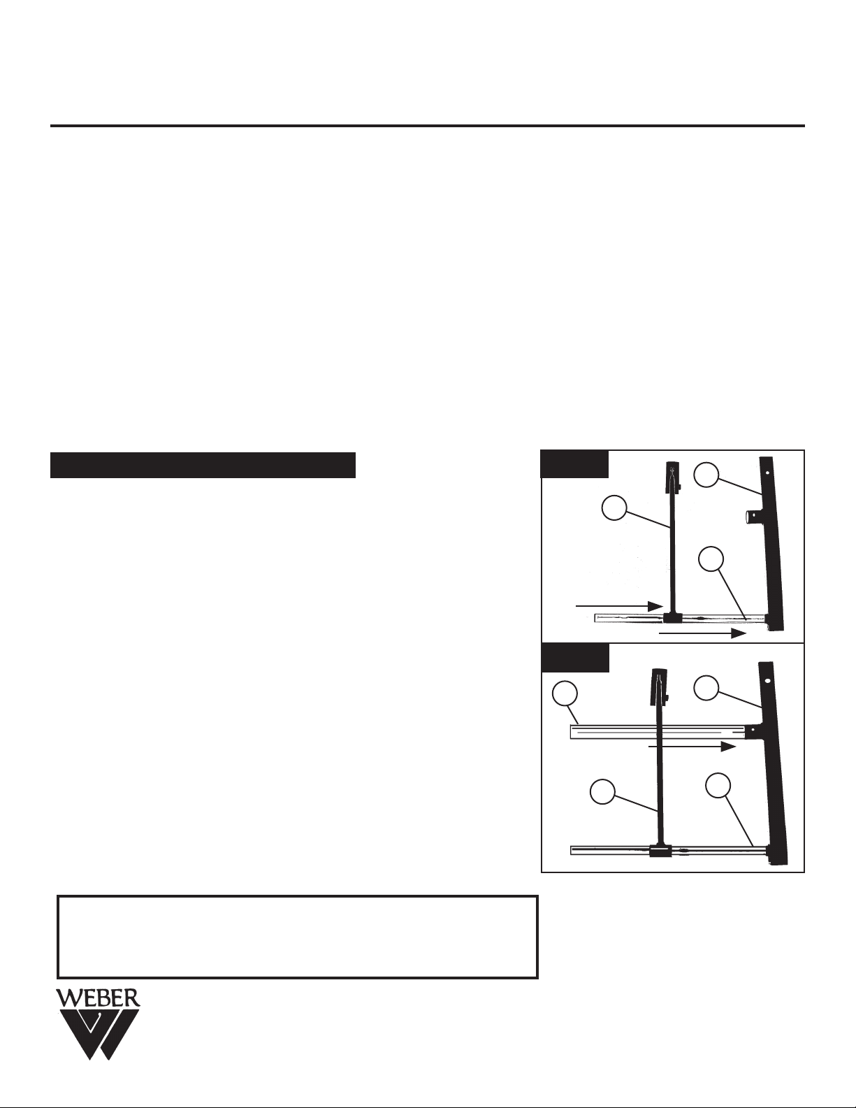
Step 1.
Begin by taking the right leg [part #2] and attaching the
11” x 17.75” chrome tube [part #5] onto the steel male-nub.
Please note you may have to tap with a rubber mallet
to securely attach tube. Continue by sliding the Tilt
Support [part #6] over the other end of chrome tube.
See FIG A.
Step 2.
Take the 1.375” x 17.75” Chrome Joiner [part #3] and insert
one end into the right leg large hole [part #2].
See FIG B.
FIG A
FIG B
3
6
2
6
5
2
5
IMPORTANT
If you have difficulty assembling your easel or need customer service assistance.
Please call: Martin Universal Design, Inc. Customer Service Hot Line at
1-800-366-7337. If you need additional parts, it is not necessary to contact your
dealer, our Customer Service Rep. will forward them to you immediately.
4444 Lawton Avenue, Detroit MI 48208 USA Tel:(313)895-0700 • Fax:(313)895-0709
created 03/14/07
E-mail: Custservmud@aol.com • Visit us at: www.MartinUniversalDesign.com
pg 1
Page 2
Avanti I - Assembly Instructions continued - Page 2 of 3
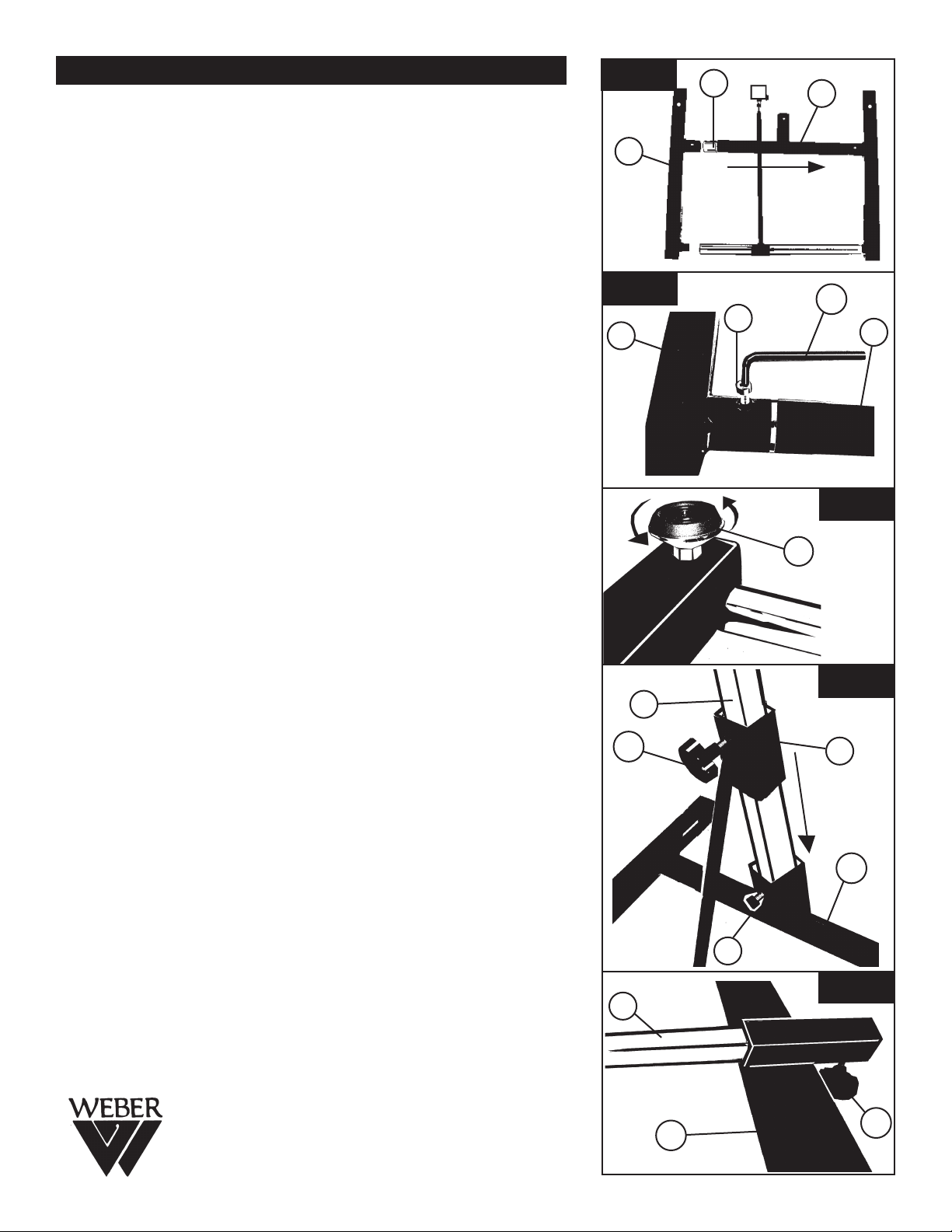
Step 3.
Continue by sliding the T-Support [part #4] over the chrome
joiner [part #3]. Continue by taking the left leg [part #1] and
connect to both ends of the chrome tube and joiner.
See FIG C.
Step 4.
Secure T-Support by attaching two allen screws [part #7]
to the left and right sides of the T-Support in the threaded
holes using Allen Wrench supplied [part #13].
See FIG D.
Step 5.
Complete base assembly by turning it over and threading
in the [4] feet [part # 12] into each of the 4 holes on base
bottom. See FIG E.PLEASE NOTE: The hole that is on
the top surface of each leg is for the
Optional Accessory Tab Tray. (Sold Separately).
FIG C
1
FIG D
1
3
4
13
7
4
FIG E
12
Step 6.
Insert Center Column [part #8] through tilt support [part #6]
and into T-Support [part # 4]. Secure at T-Support with Allen
Screw [part # 7]. Attach knob [part #11] to Tilt-Support. This
Knob allows adjustment for the Tilt of the Easel.
See FIG F.
NOTE: Do Not Over-tighten Knobs, this will
mar the surface of the chrome.
Step 7.
From top of center column [part #9] slide Large Supply
Tray [part #10] over center column. Secure by attaching
knob [part # 11]. This Knob allows to adjust the height of
the Large Supply Tray. See FIG G.
NOTE: Do Not Over-tighten Knobs, this will mar the
surface of the chrome.
11
8
FIG F
8
6
4
7
FIG G
created 03/14/07
9
11
pg 2
Page 3

Avanti I - Assembly Instructions continued - Page 3 of 3
FIG H
11
Step 9.
Slide one of the [3] Top Canvas Supports [part #11] over
top end of Center Column [part #8]. Secure by screwing
knob [part # 10] into Top Canvas Support. Repeat with 2nd
Top Canvas Support. This time slide it down upside down
(see FIG H) secure with knob, finish by sliding the third Top
Canvas Support over the top of the center column. Secure
with Knob. These Knob allow for adjustment of Top Canvas
Supports. Too adjust height, loosen Knob and slide Top
Canvas Support up or down Upper Center Column. When
desired height is achieved, re-tighten knob until secure.
See FIG H. NOTE: Do Not Over-tighten Knobs, this will
mar the surface of the chrome.
Step 10.
Easel should now look like FIG I.
ADJUSTING TILT
To adjust Tilt - loosen KNOB-A and adjust to desired tilt.
Re-tighten Knob. NOTE: Do Not Over-tighten Knobs,
this will mar the surface of the chrome.
10
This one 3rd
8
This one 2nd
11
10
This one first
10
11
FIG I
C
ADJUSTING HEIGHT OF EASEL & LARGE SUPPLY
TRAY
To adjust height of Easel, loosen KNOB-B and move upper
column to desired height. Re-tighten Knob.
PLEASE NOTE:
This will also raise or lower the Large Supply Tray.
NOTE: Do Not Over-tighten Knobs, this will mar
the surface of the chrome.
ADJUSTING TOP CANVAS SUPPORTS
To adjust one, two or three of the Top Canvas Supports,
loosen KNOBS-C and move to desired location.
Re-Tighten Knob.
NOTE: Do Not Over-tighten Knobs, this will mar
the surface of the chrome.
C
C
B
A
created 03/14/07
4444 Lawton Avenue, Detroit MI 48208 USA
Tel:(313)895-0700 • Fax:(313)895-0709
E-mail: Custservmud@aol.com
Visit us at: www.MartinUniversalDesign.com
pg 3
 Loading...