

Page 1
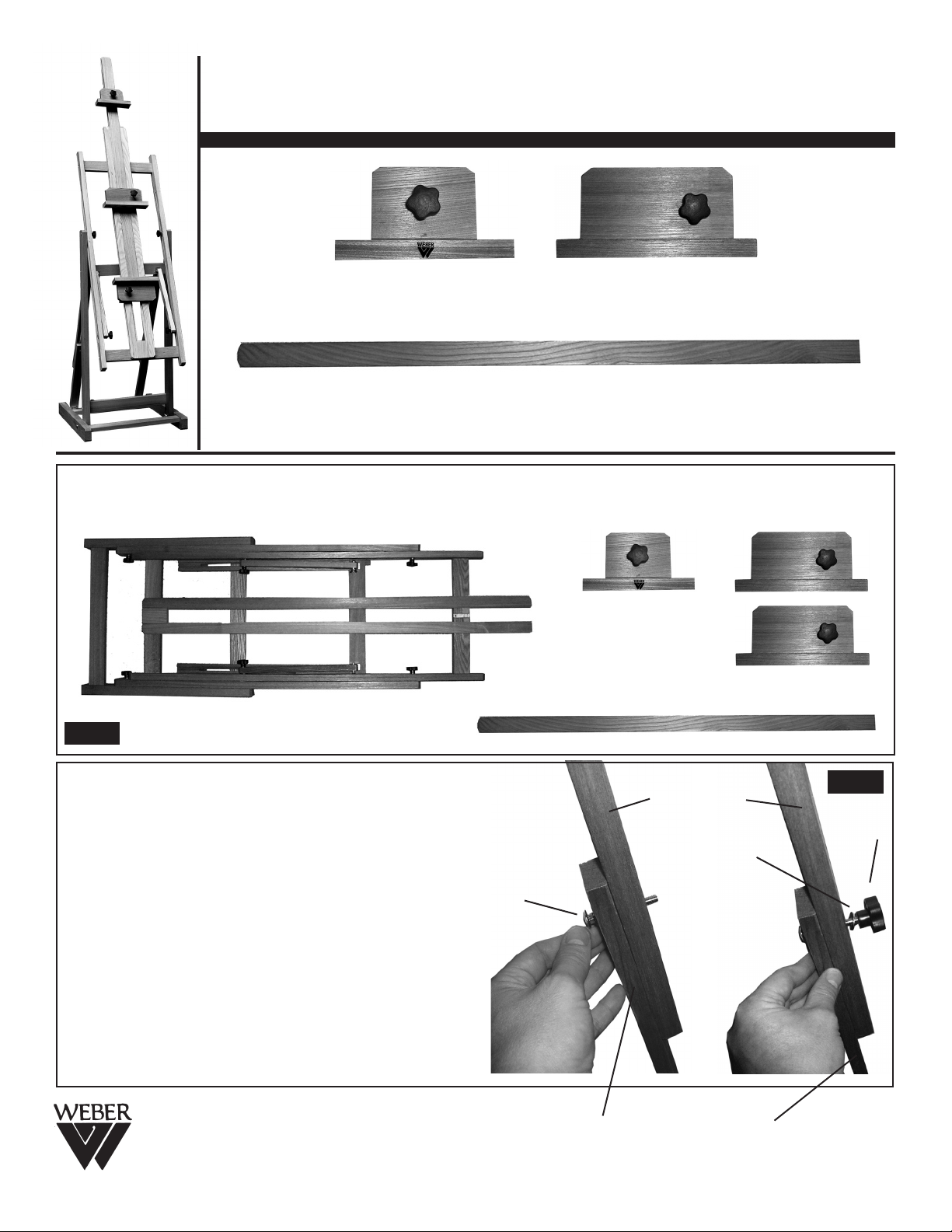
92-3014 • BOLOGNA STUDIO EASEL
ASSEMBLY/SET-UP INSTRUCTIONS
[A]
Upper Canvas Support
[C]
Side Channelled Center Column
STEP 1. Begin by removing easel assembly, Upper Canvas Support, two Large Lower Canvas Support and the one
Channelled Center Column from carton. Set pieces aside.
[B] Large
Canvas Supports
(2 each)
FIG. 1
STEP 2. Begin by Assembling the lower half of easel
by securing the upper & lower rear legs. (these pieces are
already attached to easel assembly) secure together using
the bolt, washer and female knobs.
First insert bolt through lower inside hinged leg then
through upper channelled hinged leg.
Secure with washer and knob.
See FIG 2 for illustration.
REPEAT WITH OTHER LEG.
Martin/F. Weber Co.
4444 Lawton Avenue, Detroit, MI 48208 USA
Tel:(313)895-0700 • Fax:(313)895-0709
E-mail:Custservmud@aol.com
www.MartinUniversalDesign.com • www.weberart.com
Bolt
upper channelled
hinged leg
Washer
lower inside hinged leg
FIG. 2
Knob
09/2008 RPI
FIG. 5
Page 1
Page 2
92-3014 • BOLOGNA STUDIO EASEL
ASSEMBLY/SET-UP INSTRUCTIONS
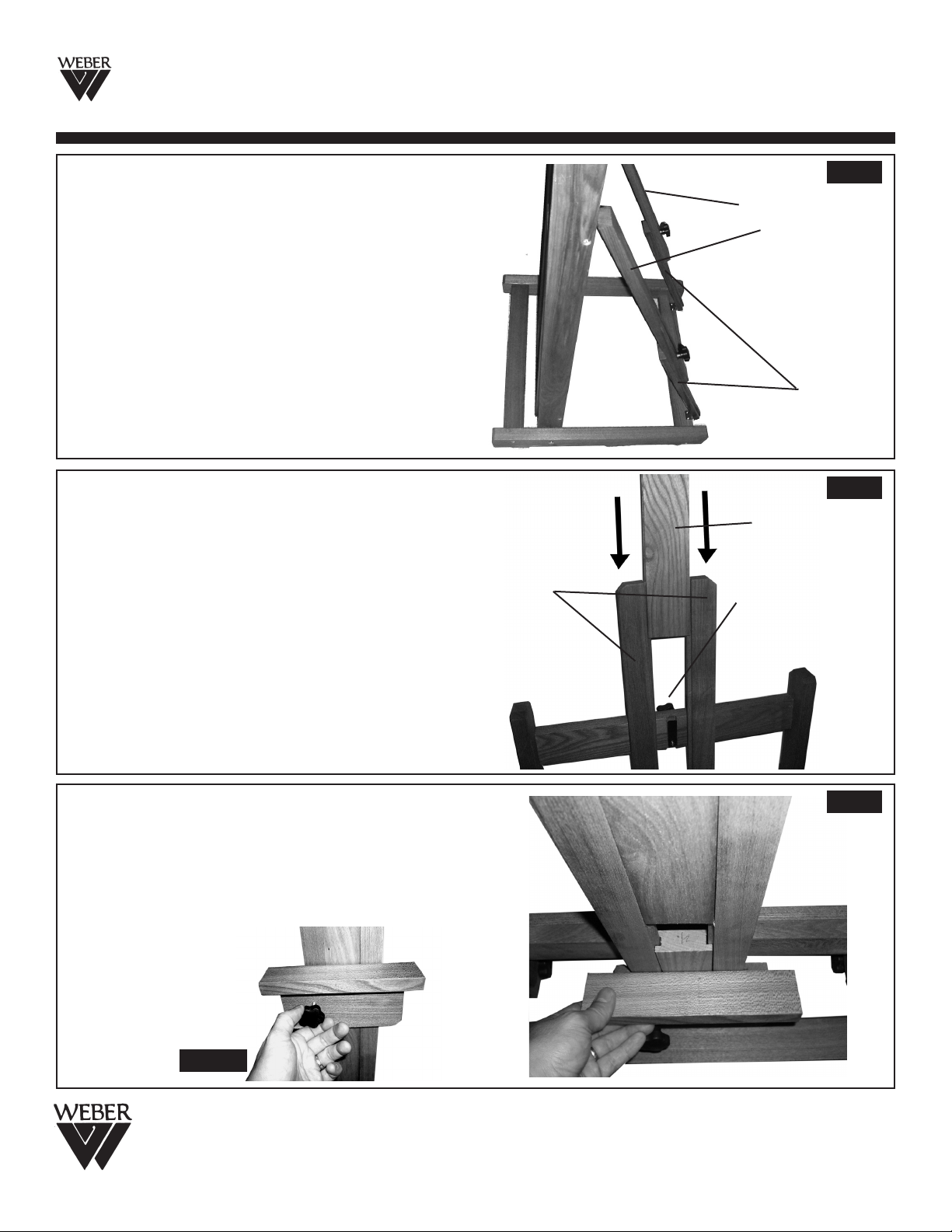
STEP 3. Lower portion of easel assembly should no
look like FIG 3. for proper assembly of upper/lower legs.
STEP 4. Attaching Channelled Center Column (part
C) into Easel Assembly. Tilt Easel assembly to allow the
center column [C] to be inserted down in between the two
center column supports. PLEASE NOTE: The flat end
of the Center Column is the bottom end of the Center
Column. This end sits flush with the bottom of the
Center Column Supports.
NOTE: The knob found on the rear of the Easel
assembly is to secure Center Column at desired
extended height.
Center Column
supports
FIG. 3
upper channelled
hinged leg
lower inside hinged leg
FIG. 4
Center Column
with Flat end
inserting first
Adjustment knob to
secure center column
at desired height.
SEE FIG 4
STEP 5. Attach one of the Lower Canvas Supports to
the Center Column Support by sliding the Lower Canvas
Support up from the bottom, making sure the supports
slide in-between the guides on the rear of the canvas
support. Se FIG 5
NOTE: Once is desired position tighten the knob to
secure. See FIG 5B
FIG. 5B
Martin/F. Weber Co.
4444 Lawton Avenue, Detroit, MI 48208 USA
Tel:(313)895-0700 • Fax:(313)895-0709
E-mail:Custservmud@aol.com
www.MartinUniversalDesign.com • www.weberart.com
FIG. 5
09/2008 RPI
Page 2
Page 3

92-3014 • BOLOGNA STUDIO EASEL
ASSEMBLY/SET-UP INSTRUCTIONS
STEP 6. Attach Middle Canvas Support to Center
Column by sliding it down over the top end of the Center
Column Frame Supports. Secure to desired position by
tightening knob. See FIG 6
STEP 7. Attach Middle Canvas Support to Center
Column by sliding it down over the top end of the Center
Column. Secure to desired position by tightening knob.
See FIG 7
FIG. 6
FIG. 7
IMPORTANT
If you have difficulty assembling your 92-3014 Weber Bologna Studio Easel or need customer service
assistance. Please call: Martin Universal Design, Inc. Customer Service Hot Line at 1-313-895-0700.
If you need additional parts, it is not necessary to contact your dealer,
our Customer Service Rep. will forward them to you immediately.
Martin/F. Weber Co.
4444 Lawton Avenue, Detroit, MI 48208 USA
Tel:(313)895-0700 • Fax:(313)895-0709
E-mail:Custservmud@aol.com
www.MartinUniversalDesign.com • www.weberart.com
09/2008 RPI
Page 3
Page 4

Adjustable Middle Canvas Support
92-3014 • BOLOGNA STUDIO EASEL
ASSEMBLY/SET-UP INSTRUCTIONS
Height Adjustable Center Column
Adjustable Upper Canvas Support
Center Column Frame Support
Adjustable H-Frame Knob. Adjusts the rotation of
the easel from vertical to horizontal position.
Adjustable Lower Canvas Support
Adjustable H-Frame Knob. These also Adjusts the
rotation of the easel from vertical to horizontal.
Negative/Positive Easel Tilt Adjustment Knobs
The Bologna Easel in the Horizontal position for the ever so
popular Watercolor technique. (See photo at left.)
This easel folds into a variety of positions and can be used to
hold two canvases.
Overall dimensions 64” high x 19.25” wide and 21” deep.
Martin/F. Weber Co.
4444 Lawton Avenue, Detroit, MI 48208 USA
Tel:(313)895-0700 • Fax:(313)895-0709
E-mail:Custservmud@aol.com
www.MartinUniversalDesign.com • www.weberart.com
09/2008 RPI
Page 4
 Loading...