

Page 1
92-3010 • MONSTER AMALFI STUDIO EASEL
ASSEMBLY/SET-UP INSTRUCTIONS
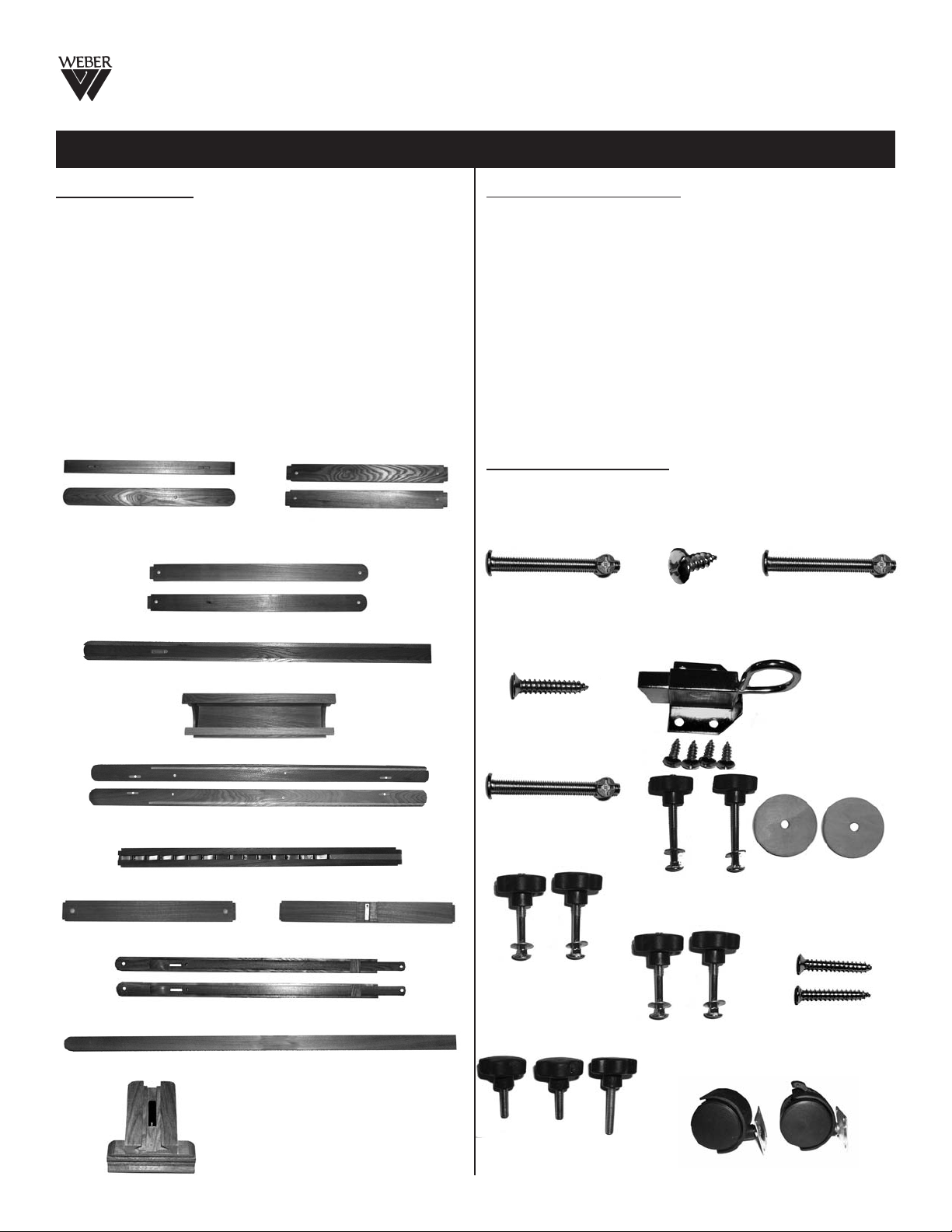
MAKE SURE CARTON CONTAINS THE FOLLOWING PARTS
WOOD PARTS
Quantity ........ Description ID#
2 ea. ........ Base Feet
2 ea. ........ Base Cross Members
2 ea. ........ Uprights
1 ea. ........
Channelled Center Column [4]
1 ea. ....... Material Tray
2 ea. ........ Channelled Side Columns
1 ea. ........ Ratchet Column
1 ea. ........ Lower Cross Member
1 ea. ........ Upper Cross Member
2 ea. ........ Extendable Rear Legs [10 & 11]
1 ea. ........ Adjustable Center Column
1 ea. ........ Upper Canvas Support [13]
Side View
Top View
Base Feet [1]
Uprights [3]
Base Cross Members
[1]
[2]
[3]
[5]
[6]
[7]
[8]
[9]
[12]
[2]
HARDWARE PARTS
Quantity ........ Description ID#
4 ea. .. Bolts & Cams: 6 X 60mm [A]
16 ea. . Screws: 4 X 16mm [B]
2 ea. .. Bolts & Cams: 6 X 60mm [C]
4 ea. . Screws: 4 X 25mm [D]
1 ea. .. Loop Mechanism & [4] Screws [E]
4 ea. .. Bolts & Cams: 6 X 60mm [F]
2 ea. .. 6 X 70mm Bolt/Knob/Washer&Wood Washer [G]
2 ea. .. 6 X 45mm Bolt/Knob & Washers [H3]
2 ea. .. 6 X 40mm Bolt/Knob & Washers [H4]
2 ea. .. 5 X 35mm Screws [H5]
3 ea. .. Knobs: 2 same size one longer
4 ea. .. Castors: 2 locking, 2 not locking
TOOLS INCLUDED
Quantity ........ Description
1 ea. ........ Flathead Screwdriver - Red Handle
1 ea. ........ Phillips Head Screwdriver - Orange Handle
6 X 60mm
Bolt & Cams
(4 each)
[A]
4 X 16mm
Srews for Castors
(16 each)
[B]
6 X 60mm
Bolt & Cams
(2 each)
[C]
Channelled Center Column [4]
Material Tray [5]
Channelled Sides [6]
Ratchet Column [7]
Lower Cross Member [8] Upper Cross Member [9]
Extendable Rear Legs [10 & 11]
Adjustable Center Column [12]
Upper Canvas Support [13]
Page 1
4 X 25mm
Screws (4 each)
[D]
6 X 60mm
Bolt & Cams
(4 each)
[F]
6 X 45mm
Bolts, Knobs & Washers
(2 each)
[H3]
3 Knobs
2 same size one longer
[unmarked]
Screws * Loop Mechanism
6 X 70mm Bolts, Knobs, Washers
& Wood Washers (2 of each)
6 X 40mm
Bolts, Knobs & Washers
(2 each)
[H4]
[4] Floor Castors (2 Locking)
3 X 12mm
[E]
[G]
5 X 35mm
Screws (2 each)
[H5]
Page 2
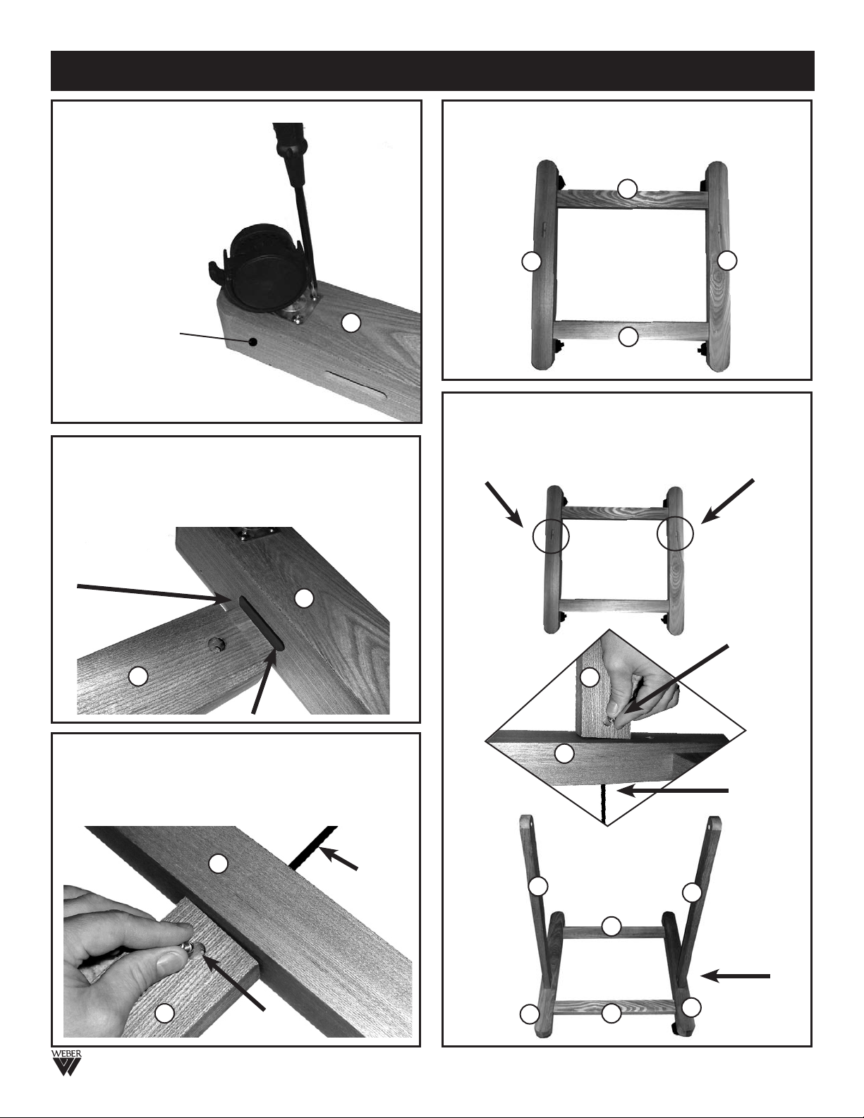
IMPORTANT - READ ALL INSTRUCTIONS BEFORE ASSEMBLING EASEL and USE 2 PEOPLE WHEN ASSEMBLING!
STEP 1. Attach the [4] castors to
the two base feet (1) making sure
the 2 locking castors are
positioned in the rear. NOTE:
the rear of the base has the hole
nearest that castor position.
Secure with four screws (B)
per castor.
See FIG 1.
Rear of the base
with hole.
STEP 2. Attach the two Base Cross members
base feet (1) By inserting the oval male end of the Base
Cross member into the oval female cut-out of the base
foot. See Fig 2. NOTE: The hole in the cross member
should be up, since the base is upside down.
Repeat with
second cross
member.
1
FIG 2
2
FIG 1
1
(2) to the
STEP 4. Turn your base assmebly over onto the
castors and you should now have a base that is
assembled like FIG 4.
2
1
2
STEP 5. This next step involves attaching the uprights
(3) to the base assembly. You will find two oval holes on
the top side of the assembled base, these oval holes
are for the oval male ends of the uprights (3) to go into.
Secure with two 6 x 60mm bolts and cams (C).
3
1
FIG 4
Insert Cam
here and
tighten bolt from
bottom of Base
with phillips
screwdriver
STEP 3. Secure Base Cross Members to base using
the four 6 X 60mm Bolts and Cams (A). Insert Cam into
hole found in Base Cross Member and insert bolt into
base foot. Tighten by holding Cam in position while
tightening down bolt with phillips screwdriver. See FIG 3.
FIG 3
2
1
Cam
Phillips
Screwdriver
FIG 5
1
6 X 600 mm
bolt here
3
2
1
2
3
After proper
assembly, base
with uprights
should look like
this.
1
Page 2
Page 3
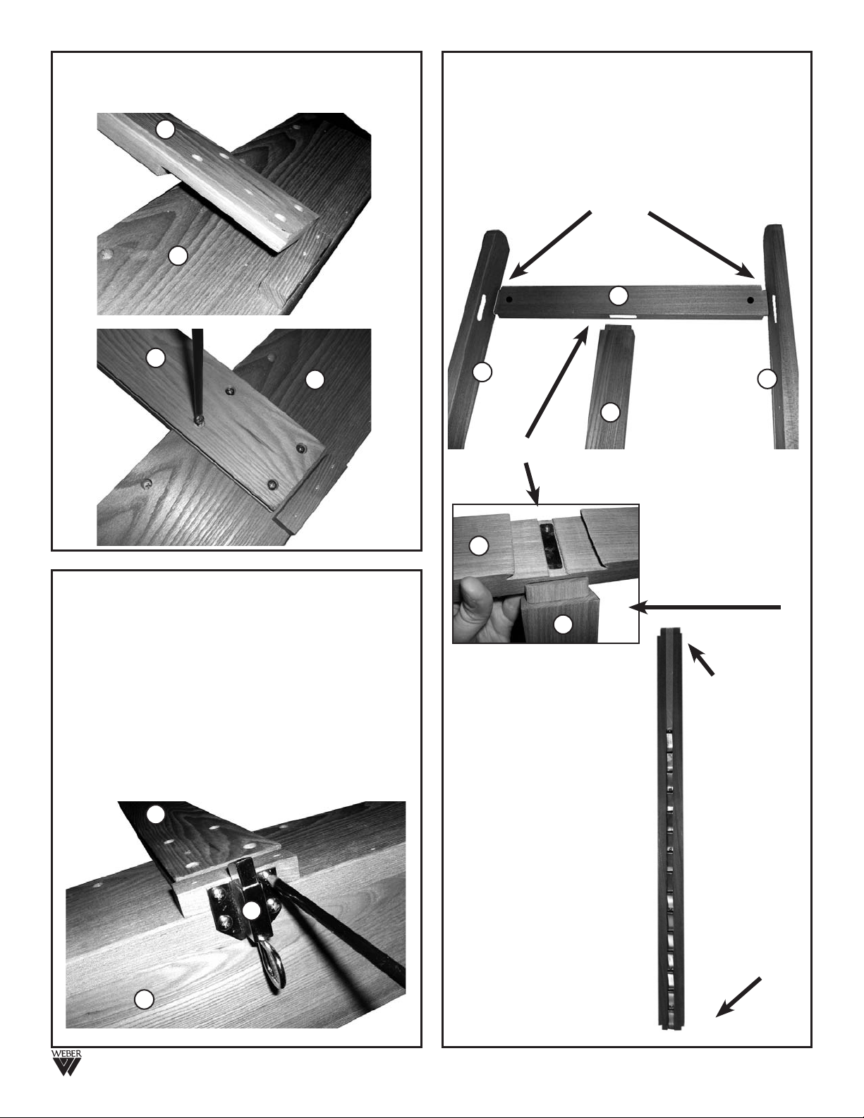
STEP 6. Attach Material Tray
Column (4) using four 4 X 25mm Screws (D).
See FIG 6a & FIG 6b.
4
(5) to Channelled Center
STEP 8a. Assembling the H-Frame. This step involves
assembling parts (6, 7, 8 & 9) to form the H-Frame
portion of the easel. Begin by taking the channelled
sides (6) & the upper cross member (9) and inserting
the oval male ends of the upper cross member into the
oval holes of the channelled sides. See FIG 8a.
Secure this step using two 6 X 60mm bolts and Cams
as previously described in earlier steps. (as in Step 3)
5
FIG 6a
4
5
FIG 6b
STEP 7. Attach Loop Mechanism
(5) using the four 3 X 12mm screws. Secure with
Phillips Screwdriver (provided) See FIG 7.
NOTE: Make sure the Loop Mechanism is in the
proper position as shown in FIG 7. This will allow
for proper adjustments when moving the material
tray up or down the Ratchet Column.
4
FIG 7
(E) to Material Tray
E
FIG 8a
9
NOTE: This image
is the rear side of
6
FIG 8b
9
7
Make sure the Ratchet column
is positioned so that the metal
part that is closest to one end
of the column is the bottom
end. See FIG 8c.
NOTE: This column is secure
once the bottom portion of
the H-Frame is assembled.
the H-Frame. The
metal portion of
the ratchet
7
column is on the
reverse side. Not
visable in this
photo.
6
STEP 8b. Continue by
inserting the ratchet
column (7) up into the
oval hole of the upper
cross member (9).
Top Portion of
Ratchet
Column
connects with
upper cross
member (9)
Bottom End
of Ratchet
Column
connects with
lower cross
member (8)
5
FIG 8c
Page 3
Page 4

STEP 10. Finish assembling the H-Frame by attaching
the lower cross member (8) to the ratchet column (7) by
inserting the ratchet column down into the oval hole of
the lower cross member. Secure by fitting the lower cross
member into the oval holes of the channelled sides (6).
See FIG 10. Secure this step, using two 6 X 60mm bolts
and Cams as previously described in earlier steps.
(as in Step 3)
7
8
6
FIG 10
6
STEP 12. Attach assembled H-Frame to easel uprights
found on assembled base. Make sure the metal ratchet
front is facing out towards the front of the easel.
This step involves securing the H-Frame assembly to the
uprights of the easel base as shown in FIG 12.
FIG 12
7
6
3
STEP 11. Your assembled H-Frame should look like
FIG 11.
NOTE: This is the front view of the assembled
H-Frame
9
7
6
6
8
STEP 13. To secure the H-Frame to the uprights, have
one person hold the H-frame while the other inserts one
part (G) 6 X 70mm Bolt through the inside edge of the
channelled sides and though the other side, then attach
one wood washer to the bolt
end. See FIG 13a.
Continue through the
upright and secure with
metal washer and black knob.
See FIG 13b.
REPEAT with other side
of H-Frame to
complete this Step.
FIG 13a
The completed
assembly should look
like FIG 13b.
3
6
3
8
FIG 11
FIG 13b
6
Page 4
Page 5

STEP 14. Attach Extendable Rear Legs (10&11) to base
(1) and upper portion of Channelled Sides (6).
Attach the wider end of the adjustable Rear legs (10) to
the base by securing with one 5 X 25mm Screw.
See FIG 14 for proper location. Secure with Phillips
screwdriver. Repeat with other Extendable Leg.
FIG 14
STEP 15. Attach upper portion of Extendable Rear Legs
(11) to upper portion of Channelled Sides (6).
Pull-out the narrower end of the extendable leg (11) and
attach it to the inside edge of the channelled sides by
inserting one 6 X 45mm bolt (H3) through the outside side
of the channelled side continuing through the extendable
leg (11) and then placing the metal washer over the bolt
and tightening with the knob to secure. See FIG 15.
See FIG 15b for proper view of assembly step 15.
FIG 15
STEP 16. Attach 6 X 40mm Bolts, knobs & washers (H4)
to Extendable legs (10 & 11). These adjustment knobs
are used along with the others to lower the easel into a
horizontal position. Insert the bolt through the inside edge
of the extendable
leg (11), continue
going though to the
other side and
complete with metal
washer and knob.
Tighten to secure.
See FIG 16.
FIG 16
STEP 17. Loosen all knobs to lower the easel into the
horizontal position. Once in flat position, tighten all knobs
to secure. See FIG 17. This step involves inserting and
sliding the Channelled Center Column (4) and Material
tray (5) assembly through the upper cross member (indicated by the circle) and guiding the material tray corners
into the channelled Sides (indicated by the squares). See
FIG 17. See inset photos below for detail.
FIG 17
H3
6
H3
11
FIG 15b
9
6
7
11
6
11
Page 5
Page 6

STEP 18. Once Channelled Center Column is in its
proper location in the upper Cross Support, secure with
the longest of the three remaining knobs by threading the
threads of the knob in the hole in the rear of the cross
support. Tighten to secure. See FIG 18.
4
9
STEP 20. Final step involved in the assembly of your
New 92-3010 Easel.
Attach the Upper Canvas Support (13) to the Adjustable
Center Column (12) by sliding the grooves of the canvas
support down into the channels of the Adjustable Center
Column. Do this from the top end of the Adjustable
Center Column. Secure with remain knob. tighten to
secure at desired position. See FIG 20
12
7
FIG 18
STEP 19. This step involves adding the Adjustable
Center Column (12) down into the Channelled Center
Column (4). See FIG 19. To secure into place, thread one
of the remaining two shorter knobs into the hole found on
the rear of the Channelled Center Column. See FIG 19b.
12
FIG 19
4
Rear view of
Channelled Center
Column where knob
4
FIG 19b
is to be threaded.
13
FIG 20
ADJ 1. Adjusting Height Material Tray.
Insert finger in locking loop pin below Material Tray and
pull outward. This will cause the material tray support to
release from the metal ratchet column allowing you to
raise or lower the material tray and center column.
PLEASE NOTE: Be careful when raising the
material tray, that you are aware that the top of the
column will not interfere with ceiling or any other
object in rooms that have low ceilings.
IMPORTANT
If you have difficulty assembling your 92-3010 Weber Monster
Amalfi Studio Easel or need customer service assistance.
Please call: Martin Universal Design, Inc. Customer Service Hot
Line at 1-313-895-0700. If you need additional parts,
it is not necessary to contact your dealer, our Customer Service
Rep. will forward them to you immediately.
Martin/F. Weber Co. • 4444 Lawton Avenue, Detroit, MI 48208 USA
Tel:(313)895-0700 • Fax:(313)895-0709 • E-mail:Custservmud@aol.com
www.MartinUniversalDesign.com • www.weberart.com • Made in China
Created NOV07RPI
Page 6
Page 7

92-3010
Extendable Rear legs (11)
Extendable Rear legs (10)
Base Foot (1)
Base Cross Support (2)
Locking Castor
Weber Monster Amalfi Studio Easel
Upper Canvas Support (13)
Adjustable Center Column (12)
Upper Cross Member (9)
Adjustable Material Tray
Height Adjustable Center Column/Material Tray
by pulling loop out from ratchet system
Ratchet Cloumn (7)
Lower Cross Member (8)
Uprights (3)
Martin/F. Weber Co.
4444 Lawton Avenue, Detroit, MI 48208 USA
Tel:(313)895-0700 • Fax:(313)895-0709
E-mail:Custservmud@aol.com
www.MartinUniversalDesign.com • www.weberart.com • Made in China
Created NOV07 RPI
(5)
Page 7
 Loading...