

Page 1
92-2100 • MURANO Professional Studio Easel
ASSEMBLY INSTRUCTIONS
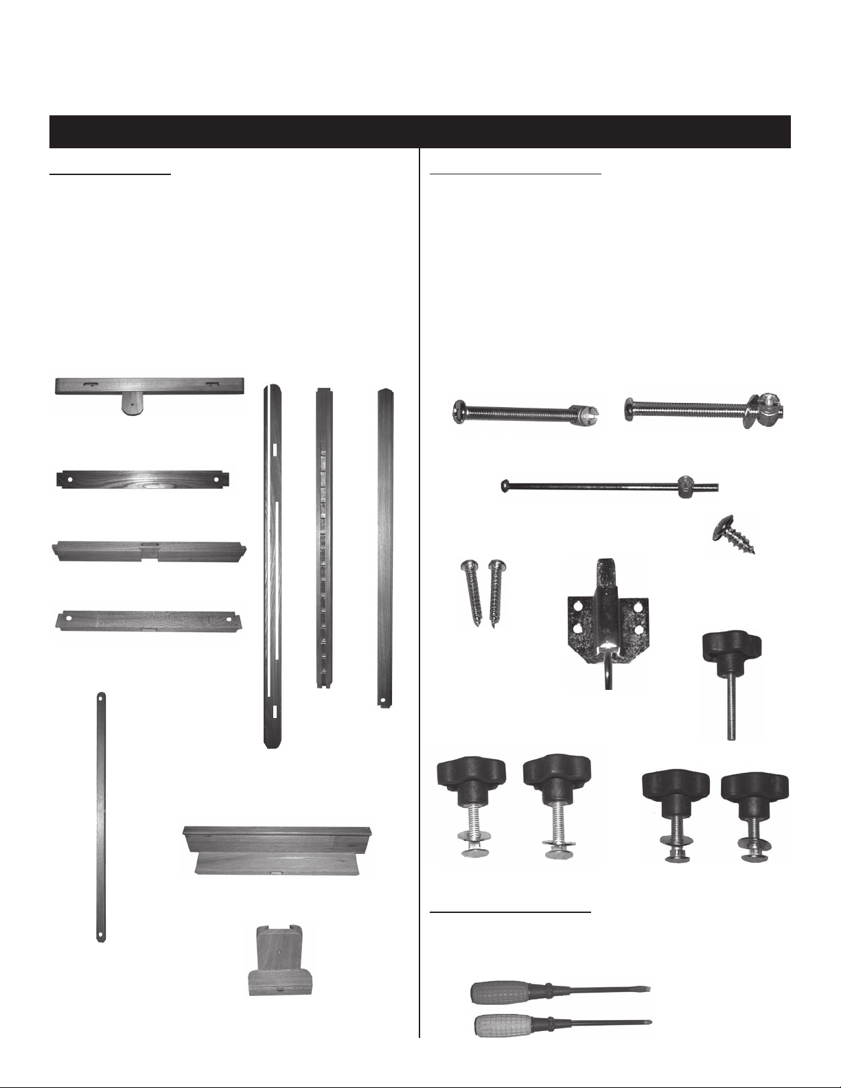
MAKE SURE CARTON CONTAINS THE FOLLOWING PARTS
WOOD PARTS
Quantity ........ Description ID#
2 ea. ........ Base Foot [1]
2 ea. ........ Base Foot Connectors [2]
2 ea. ........ Side Arms (1 Left & 1 Right) [3]
1 ea. ........ Upper Side Arm Connector [4]
1 ea. ........ Lower Side Arm Connector [5]
1 ea. ....... Center Ratchet Column [6]
1 ea. ........ Center Column [7]
1 ea. ........ Lower Canvas Tray [8]
2 ea. ........ Side Leg Angle Supports [9]
1 ea. ........ Upper Canvas Support [10]
Base Foot [ID# 1]
Base Foot Connectors
[ID# 2]
HARDWARE PARTS
Quantity Description ID#
4 ea. ........ 6 x 60mm Carriage Bolts and T-nuts [A]
4 ea. ........ 6 x 50mm Carriage Bolts/Wash & T-nut [B]
1 ea. ........ 6 x 120mm Carriage Bolt and T-nut [C]
2 ea. ........ 6 x 45mm Wood Screws [D]
1 ea. ........ Loop-Pull Mechanism [E]
4 ea. ........ Small Wood Screws (with Loop-pull) [F]
1 ea. ........ 2.25” Knob - male [G]
2 ea. ........ Bolt 6x45mm, Knob & Washer [H]
2 ea. ........ Bolt 6x35mm, Knob & Washer [ I ]
Carriage Bolt with T-Nut
6 x 60mm [ID# B]
Carriage Bolt with T-Nut
6 x 120mm [ID# C]
Carriage Bolt with Washer & T-Nut
6 x 50mm [ID# A]
Upper Side Arm Connector
[ID# 4]
Lower Side Arm Connector
[ID# 5]
Side Leg Angle
Supports
[ID# 9]
Created June 06 RPI
Center
Ratchet
Column
[ID# 6]
Side Arms
[ID# 3]
Lower Canvas Tray
[ID# 8]
Upper Canvas
Support
[ID# 10]
Center
Column
[ID# 7]
Small Wood
Screws
[ID# F]
6 x 45mm Wood
Screws
[ID# D]
Loop-pull Mechanism
[ID# E]
2.25” Knob [ID# G]
Bolt 6 x 45mm, Knob & Washer
[ID# H]
Bolt 6 x 35mm, Knob & Washer
[ID# I]
TOOLS INCLUDED
Quantity ........ Description ID#
1 ea. ........ Flat Screwdriver [X]
1 ea. ........ Phillips Screwdriver [Y]
[X]
[Y]
Page 1
Page 2
For recommended assembly lay all wood parts on flat surface with all holes facing up.
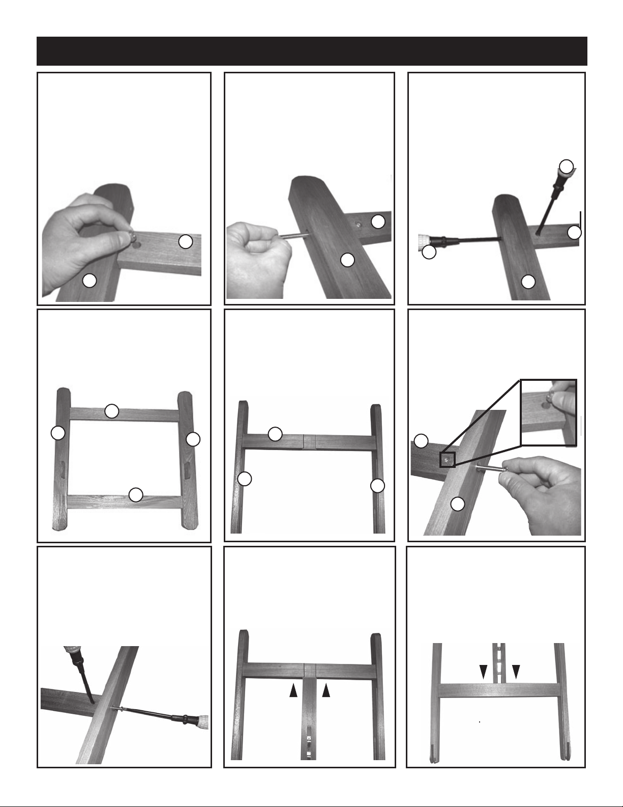
STEP 1. Assembling Base.
Take each Base Foot [ID#1] (make
sure wood hinges are on top.) along
with each Base Foot Connectors
- Make sure holes are on bottom
of base. [ID#2]. Insert T-Nut from
Carriage Bolt [ID# A] into hole in
Base Foot Connector. See FIG 1.
Repeat on all 4 sides.
FIG 1
2
1
STEP 4. Assembled Base.
The Base assembly should look like
FIG 4. NOTE: Holes where T-Nuts
should be located on bottom of
assembled base, if properly
assembled.
STEP 2. Assembling Base.
After inserting T-Nuts, continue by
inserting Carriage Bolt (6x60mm)
into the sides of the Base Foot
[ID#1] making sure bolt screws into
T-nut by aligning T-nut opening with
bolt. Repeat for each of the
remaining 3 sides. See FIG 2.
FIG 2
2
1
STEP 5. Assembling Side Arms.
Start by taking the two side arms
[ID#3] and the upper side arm connector [ID#4]. Position as shown in
FIG 5. Please note: The ends of the
side arms that have slots are the
bottom ends.
STEP 3. Assembling Base.
Secure each Carriage bolt by
attaching bolt with Philips
Screwdriver [ID#Y]. Use the Flat
Screwdriver [X] to hold the T-Nut in
place. See FIG 3.
X
FIG 3
2
Y
1
STEP 6. Assembling Side Arms.
Insert T-nut into upper arm
connector. Continue by inserting
carriage bolt 6x50mm into hole on
side of Side arm and into T-nut.
See Fig 6.
FIG 6
2
1
FIG 4
2
STEP 7. Assembling Side Arms.
Secure Carriage bolt by attaching
bolt with Philips Screwdriver [ID#Y].
Use the Flat Screwdriver [X] to hold
the T-Nut in place. Repeat with
other side. See FIG 7 & FIG 5 for
final result of this step.
1
FIG 7
4
3
FIG 5
STEP 8. Ratchet Center Column
Insert Ratchet Center Column up
into slotted section of upper side arm
connector. Make sure ratchet center
column is positioned as shown in
FIG 8.
FIG 8
3
4
3
STEP 9. Lower Side Arm Connector
Insert Ratchet Center Column down
into the oval hole on the end of the
lower side arm connector. Make sure
ratchet center column is positioned as
shown in FIG 9. T-nut Holes in
connector should be on backside.
Pg. 2
FIG 9
Created June 06 RPI
Page 3

STEP 10. Center column to Lower
Canvas Tray
Insert Center Column [ID#7] into
oval slot on top edge of Lower Canvas Tray [ID#8]. Insert T-nut from
part [ID#C]. See FIG 10.
FIG 10
7
STEP 11. Center column to Lower
Canvas Tray continued
Insert Carriage bolt [ID#C] into hole
in bottom end of Lower Canvas
Tray [ID#8]. Using phillips screw
driver [ID# Y] tighten and secure
bolt into T-nut. See FIG 11.
7
FIG 11
STEP 12. Attaching Loop-pull to
Lower Canvas Tray
Attach Loop-pull mechanism [ID#E]
to bottom end of Lower Canvas Tray
using [4] small wood screws [ID#F].
See FIG 12.
7
8
STEP 13. Attaching Center Column
to Side Arm Frame Assembly.
With Side Arm Frame Assembly
laying face up on carpeted surface,
slide Center column’s angled edge
up through Upper side arm connector
[ID#4]. See FIG 13.
3
7
6
4
FIG 13
8
STEP 14. Attaching Center
Column to Side Arm Frame
Assembly, continued...
When attaching Center column to
Side Arm Frame Assembly line up
grooves in Lower Canvas tray to
channels in Side Arms. See FIG 14.
8
3
FIG 14
8
E
FIG 12
STEP 15. Loop-pull Adjustment
To allow Center column to move
freely, you must pull up on loop-pull
mechanism [ID#E]. See FIG 15.
7
E
6
FIG 15
5
STEP 16. Upper Canvas Support
Attach Upper Canvas Support, by
sliding it down over the Center
Column. Secure with Knob [ID#G].
NOTE: Loosen Knob to move Upper
Canvas Support to desired position
once Easel is assembled.
See FIG 16.
G
10
7
FIG 16
Created June 06 RPI
STEP 17. Side Leg Angle Supports
Attach Side Leg Angle Supports
[ID#9] to Side Arms using the [2]
Knobs [ID#H], washer and bolt.
NOTE: make sure angle support is
attached to inside of Side Arm.
See FIG 17.
9
3
FIG 17
STEP 18. Side Leg Angle Supports.
Continued...
See FIG 18 for the correct order of
attachment.
Side Arm
Washer
Angle Support
Knob
6x45mm
Bolt
3
9
FIG 18
Pg. 3
Page 4

STEP 19.
Side Arm Frame Assembly to Base Attachment
STEP 20.
Side Leg Angle Support to base assembly
With Base laying face-up on
carpeted floor, line up notched grooves on bottom ends of
the Side Arm Frame Assembly with wooden supports on
base. Secure with Knob, washer and 6x35mm bolt [ID#I].
Insert bolt through inside side of side arm through base
foot, then back through other side of side arm. Attach
washer and then secure with knob.
Repeat with other side.
See FIG 19.
NOTE: This knob can be loosened when angle of
easel needs to be adjusted. Re-tighten when desired
angle is achieved.
3
1
Attach side leg angle support [ID#9] to base using one
6x45mm wood screw [ID#D]. Repeat with other side.
Tighten with phillips screwdriver [ID#Y].
See FIG 20.
9
1
D
Y
FIG 19
Angle Adjustment:
Loosen knobs on side leg angle supports and tighten at
desired angle.
Height Adjustment of Center Column:
Unlock loop-pull on lower canvas support, adjust to desired height and release loop-pull.
Enjoy your Easel!
If you have any problems with assembling this
easel, please call (313)895-0700 or e-mail us at
Custservmud@aol.com.
Thank You.
FIG 20
Easel should
like photo to
right after
correct
assembly.
Martin/F. Weber Co. • 4444 Lawton Avenue, Detroit, MI 48208 USA
Tel:(313)895-0700 • Fax:(313)895-0709 • E-mail:Custservmud@aol.com
www.MartinUniversalDesign.com • www.weberart.com
Made in China
Created June 06 RPI
92-2100
Murano
Professional
Studio Easel
Pg. 4
 Loading...