

Page 1
IMPORTANT NOTICE
YOU WILL FEEL A SLIGHT
“BOUNCE-BACK” WHEN YOU SIT DOWN.
THIS IS NORMAL: NOT A DEFECT.
THE PNEUMATIC CYLINDER FOR THE
SEAT HEIGHT ADJUSTMENT REACTS TO
YOUR WEIGHT BY GIVING A LITTLE
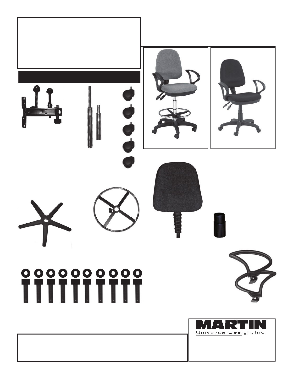
Parts
VESUVIO Model’s
91-8006 & 91-8009
Gray
Fabric
Black
Fabric
A. [1] Base Plate
Mechanism
D. [1] Plastic Ring insert
Model 91-7706 only
(This part can be found in
the foot ring Part F)
a.
b.
B. [1] Cylinder
[a] 91-8006 model
[b] 91-8009 model
C. [5] Castors
Assembled 91-8006
Assembled 91-8009
H. [1] Seat
K. [1] Black Cylinder
Bellows
Model 91-8009 only
F. [1] Foot Ring with Knob
Model 91-8006 only.
E. [1] 5-Star Base
I. [10] M6x20 Hex Head Screws
IMPORTANT
If you have difficulty assembling your chair or need customer service assis-
tance. Please call: Martin Universal Design, Inc. Customer Service Hot Line at
1-800-366-7337. If you need additional parts, it is not necessary to contact your
dealer, our Customer Service Rep. will forward them to you immediately.
G. [1] Backrest
L.
[4] 3/4”
Plastic
Washers
for armrest
attachment
M. [2] Loop
Armrests
4444 Lawton Avenue, Detroit MI 48208 USA
Tel:(313)895-0700 • Fax:(313)895-0709
E-mail: Custservmud@aol.com
Visit us at: www.MartinUniversalDesign.com
MUD 10/2009
Page 2
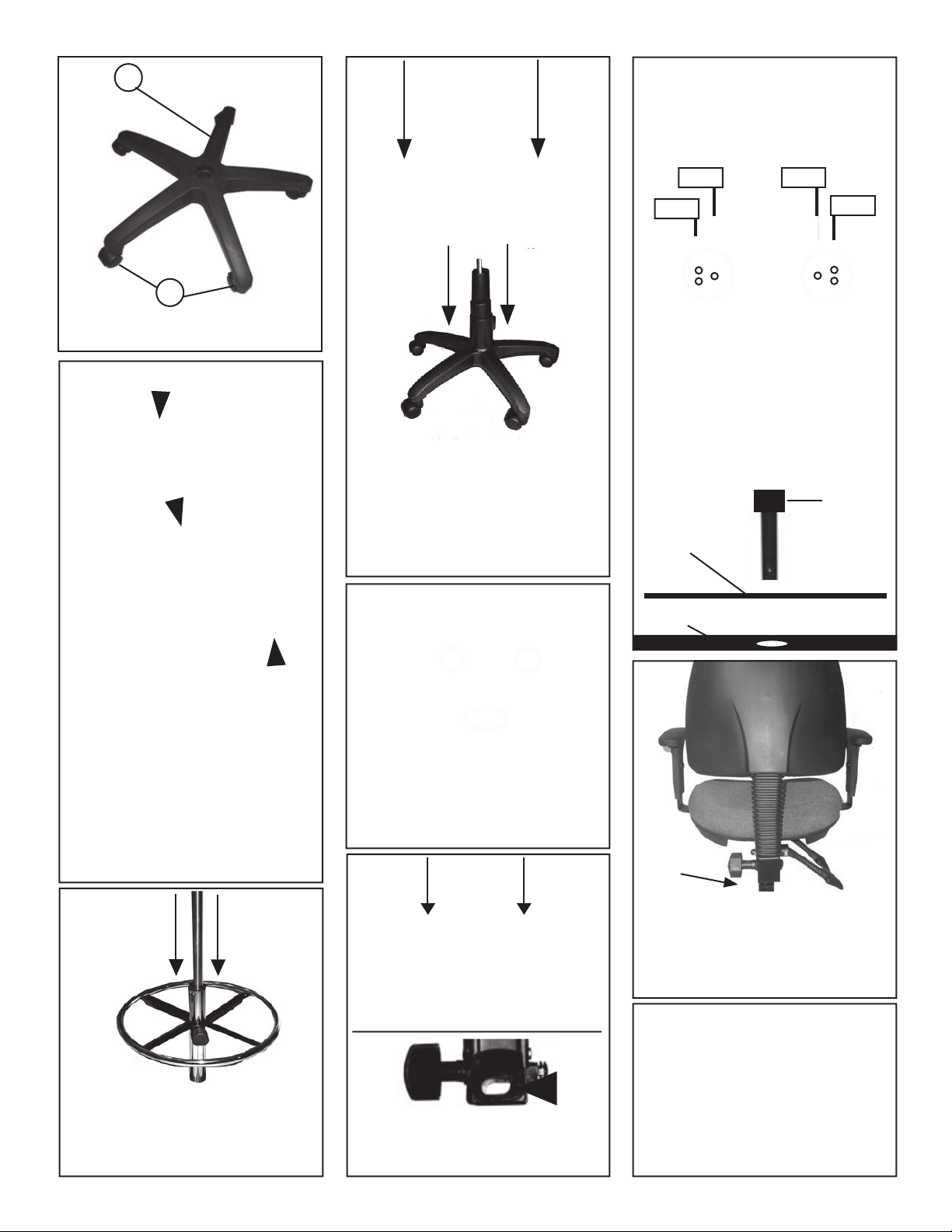
1.
E
Model #
91-8006
4.
7.
C
Place 5-star base (E) face down and
push [5] castors (C) into each position.
knob on foot ring
2.
weld
Cut ends of plastic
insert must run parallel
with the weld.
Model #
91-8009
PLEASE NOTE: If you have model
number 91-8009, your assembly will
be the same but instead of foot ring
you will need to place black bellows
over top of cylinder after inserting
cylinder into base.
Insert wider end of cylinder into hole in
base, as shown above.
5.
M6x20
M6x20
Attach armrests to bottom side of seat.
Each Armrest (M) uses [3] M6x20
screws (I). Tighten with Hex-wrench.
Armrest bracket
Seat Bottom
M6x20
M6x20
Screw
THIS STEP IS ONLY FOR
MODEL 91-8006 ONLY.
Before attaching foot ring (F) to cylinder
(B). Begin by loosening the knob on the
foot ring and make sure the plastic ringis
inserted properly, by making sure the
cut ends of the insert run parallel with
the weld on the inside of the foot ring
hole. The insert should be already in the
foot ring. NOTE: THIS MUST BE
POSITIONED PROPERLY TO ALLOW
THE CYLINDER TO SLIDE THROUGH
THE INSERT EASILY.
3.
Slide cylinder down through foot
ring and tighten knob . After chair is
assembled completely, you may adjust
foot ring to desired height.
Attach mechanism (A) to seat (H) using
[4] M6x20 hex head screws (I). See pic
above for specified locations that are
circled. Tighten with hex wrench.
6.
Attach backrest (G) to seat mechanism,
by inserting backrest support bar into
oval hole in mechanism. Tighten knob
on mechanism to secure.
8.
Attach seat/backrest/armrest assembly
to cylinder by inserting top of cylinder
into hole on bottom of seat mechanism.
Weight of sitting on seat will secure seat
assembly to cylinder.
NOTE: 2 Paddles below seat
are for seat height adjustment
and Backrest tilt adjustments.
NOTE2:
PERIODIC RE-TIGHTENING
of Armrests screws may be
needed throughout use of
chair over the years.
MUD 10/2009
 Loading...