

Page 1
IMPORTANT NOTICE
YOU WILL FEEL A SLIGHT
“BOUNCE-BACK” WHEN YOU SIT DOWN.
THIS IS NORMAL: NOT A DEFECT.
THE PNEUMATIC CYLINDER FOR THE SEAT
HEIGHT ADJUSTMENT REACTS TO YOUR
WEIGHT BY GIVING A LITTLE
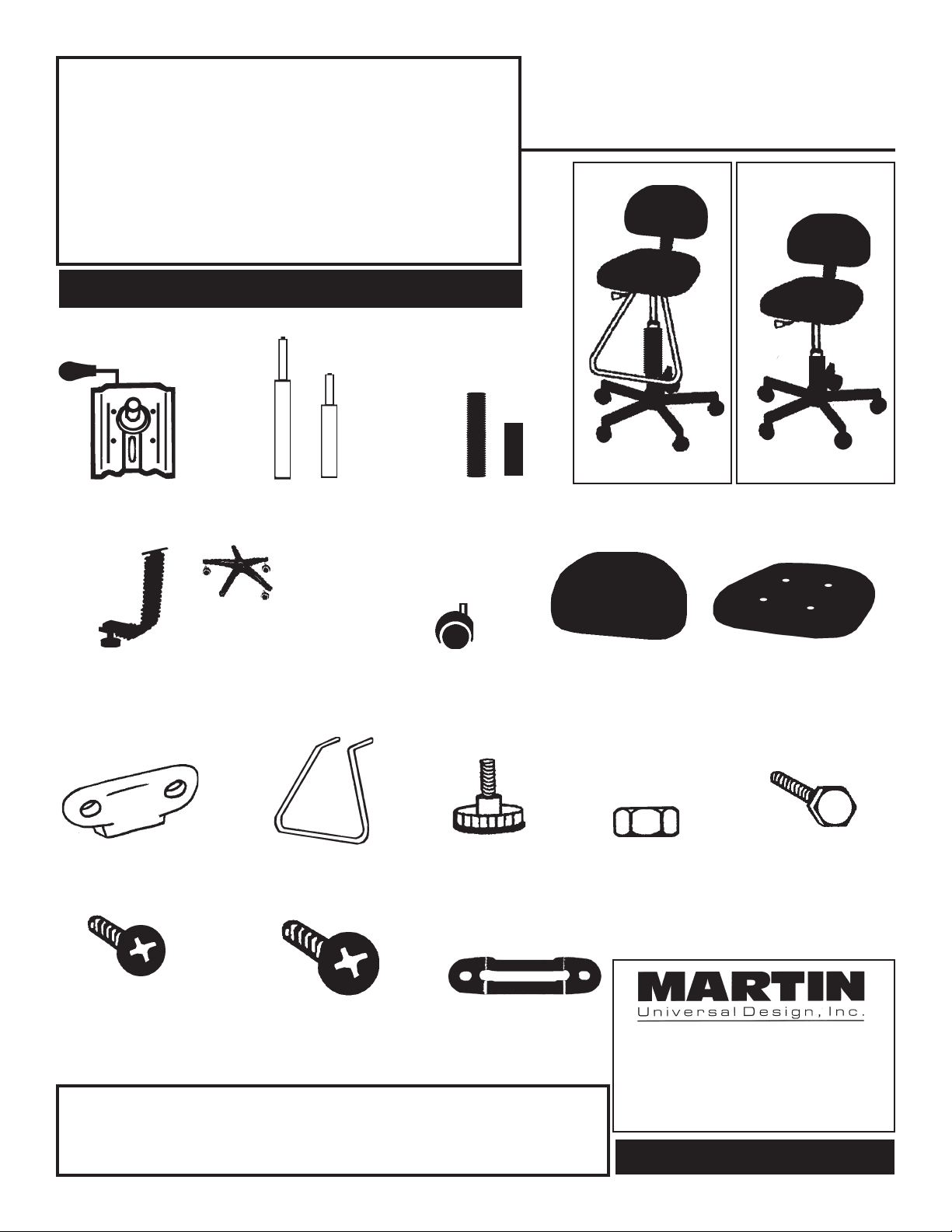
Parts
a.
b.
a.
b.
Model
91-6008 & 91-6009
A. [1] Base Plate &
Lever
D. [1] Backrest
Support Bar
Note: Part [K] is
attached to part [D]
I. [1] Backrest
Cover
B. [1] Cylinder
[a] bellows 91-6008 model
[b] bellows 91-6009 model
E. [1] 5-Star
Base
J. [1] Footrest
Model 91-6008 only.
Assembled 91-6008
C. [1] Bellows
[a] bellows 91-6008 model
[b] bellows 91-6009 model
F. [5] Push-in
Castors
K. [1] Knob
Note: This knob is
attached to Part [D]
G. [1] Backrest H. [1] Seat
Assembled 91-6009
Note: Part [N] 4 screws
are attached to part [H]
L. [4] Nuts M. [4] Bolts
Model 91-6008 only.
N. [4] 3/4” Black
Screws
Note: These screws are
attached to Part [H]
If you have difficulty assembling your chair or need customer service assis-
tance. Please call: Martin Universal Design, Inc. Customer Service Hot Line at
1-800-366-7337. If you need additional parts, it is not necessary to contact your
dealer, our Customer Service Rep. will forward them to you immediately.
O. [2] 1” Black Screws
IMPORTANT
P. [1] Metal Backrest
Plate
4444 Lawton Avenue, Detroit MI 48208 USA
Tel:(313)895-0700 • Fax:(313)895-0709
E-mail: Custservmud@aol.com
Visit us at:
www.MartinUniversalDesign.com
PAGE 1
MUD0107
Page 2
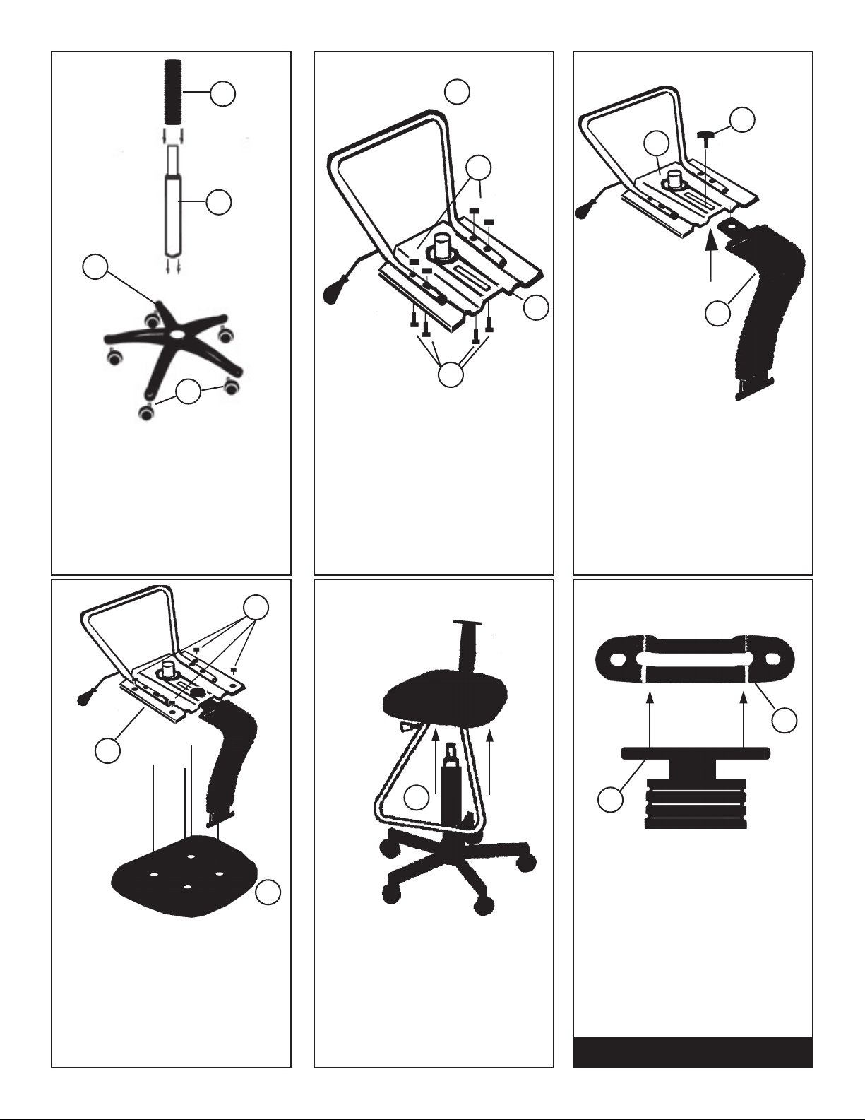
1.
E
B
C
2.
J
3.
K
A
L
F
Place base (E) face down and push
castors (F) in firmly. Insert cylinder
(B) through base cap into chair
base. Twist and press firmly.
Slide Bellows (C) down over
cylinder.
4.
N
A
NOTE:
FIG. Shown
with Footbar.
Model
91-6009 not
equipped
with Footbar.
A
M
THIS STEP IS ONLY FOR
MODEL 91-6008
Attach foot bar (J) to base plate (A)
using [4] Silver Bolts (M) and [4]
nuts (L). Line up holes in footbar to
holes in seat plate. Tighten securely.
5.
NOTE:
FIG. 5.
Shown with
Footbar.
Model
91-6009 is
not equipped
with
Footbar.
B
D
NOTE:
FIG. Shown with
Footbar. Model
91-6009 not equipped
with Footbar.
Attach support bar with bellows (D)
to seat plate (A) by sliding the bar
into the raised area of the seat plate
(see arrow for location).
Thread Knob (K) into hole in seat
plate, making sure knob threads
through seat plate.
6.
P
D
H
With seat cushion lying plastic side
up, line up [4] holes in seat plate (A)
with [4] holes in seat cushion (H).
Attach with [4] 3/4” black screws
(N). Tighten securely. Please Note:
Foot bar should face front of seat
cushion (Front of cushion has label
attached.)
Take the complete seat assembly
and insert the seat plate over the
cylinder (B) by inserting the cylinder
into the hole on the bottom of the
seat plate (A).
Attach backrest plate (P) to backrest
support bar (D) by inserting backrest support bar “T” into longated
slot in backrest plate (P). Continue
with Step 7.
PAGE 2
MUD0107
Page 3

7.
P
8.
I
D
If properly assembled, the backrest plate (P) and
backrest support bar (D) should look like the above
photograph. Once this is achieved move on to Step 8.
Continue by taking the Backrest Cover (I) and placing it
into position onto the backside of the backrest plate (P).
NOTE: The metal backrest plate should lay flat against
the backrest cover (I).
9. 10.
D
The Backrest Support bar should now look like the
above photograph. This Backrest Support Bar is now
ready to have the backrest (G) attached to it.
NOTE: Backrest Support should be attached to seat as
displayed in Step 4.
Attach Backrest Support assembly (Parts D, I & P) to
upholstered back using the [2] black screws provided
making sure the screw holes in backrest cover (I) line up
with the screw holes in the upholstered back.
Tighten screws securely.
P
D
9.
IMPORTANT
If you have difficulty assembling your chair or need
customer service assistance. Please call: Martin Universal
Design, Inc. Customer Service Hot Line at
1-800-366-7337. If you need additional parts, it is not
necessary to contact your dealer, our Customer Service
Rep. will forward them to you immediately.
4444 Lawton Avenue, Detroit MI 48208 USA Tel:(313)895-0700 •
Fax:(313)895-0709
E-mail: Custservmud@aol.com
Visit us at:
www.MartinUniversalDesign.com
PAGE 3
 Loading...