

MartinLogan Motion 20, Motion 40 User Manual
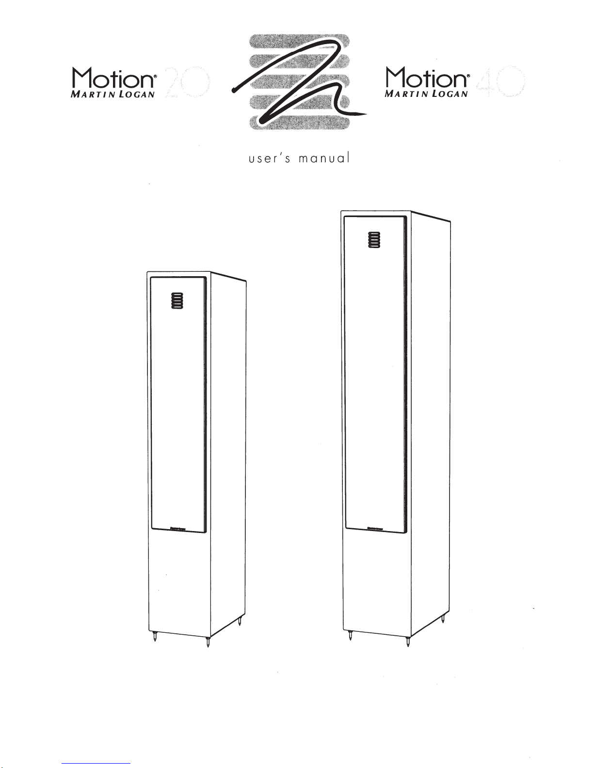
Motion·
MARTIN
LOGAN
Motion·
MARTIN
LOGAN
user's
manual
-
-
-
-
•
Refer
seryieing
tec~DJciq~
•
TO
prevent ·fire<pr.shock.hazard,
do
not
exposet~·nsmodule
•
Turn
amp~ifiefoff
.. .
to
a·
quotified
ii.·••
·•·•···
·····•.••·•·····•·•
..
<
<
to
r
sh6uld
ony
abnormal
rnoi
.
sture.
conditions occur.
•
Do
.
not
drivt?
• speaker
The
lightning bolt flash
symbol,
is
intended to
ence
of
potentially
product's
tute
ating and maintenance (servicing) instru.ctions
literature accompanying the
~
A
t3AUG2oos
2005,
may contain regulated materials
al,
reuse
Logan
Union member nations
uct
enclosure
a
risk
of
electric
The exclamation point within an equilateral triangle
user to the presence
In
accordance
WEEE
Equipment) directive effective August 1 3,
we
according to the WEEE directive, require
and
has
at no cost
(Waste
would
like
recycling processing.
arranged with our distributors
to
you.
beyond
within an
"dangerous
that
may
shock.
with the European Union
Electrical
to notify you that this product
to
collect
its
·
rated
with arrowhead
equilateral triangle,
alert
the
user
voltage"
be
sufficient to consti-
is
intended
of
important oper-
appliance .
and
which upon dispos-
For
this
reason Martin
in
and
recycle
power,
to
the
within the
to
alert
Electronic
European
this
special
pres-
in
prod-
the
the
Connection
jumper Clips
Single
. . . . . . . . . . . . . . . . . . . . . . . . . . . . 4
.......................
Wire
Connection
Bi-Wire Connection
Passive
Bi-Amplification . .
Active Bi-Amplification
Assembly
Break
Placement.
Toe-In
Installing
Solid
Frequently
Troubleshooting
Contacting
General
Warranty
Serial
Service .
Specifications
Dimensional
and
Placement
In
................
.
. . . . . . . . . . . . . . . 6
. . . . . . . . . . . . . . . . . . .
the
Grill
Covers .
Footing
.......................
Asked
Questions
. . . . . . . . . . . . . . . . . . . . . . . . 9
Customer
Information
Information
Number. . .
. . . . . . . . . . . . . . .
. . . . . . . . . . . . . . . . . . . . . . . . .
Drawings
Martinlogan Motion
Martinlogan Motion
Serial
Number:
Record your
You
will need
---------------------------
serial
number here for easy reference.
this
information when filling
warranty registration.
near
the
binding
posts
...............
..................
...
...........
.........
.
.......
.................
.
.........
....
..
........
. . . . . . . . . . . . . . . 9
Service
. . . . . . . . . . . . . 9
....................
................
. . . . . . . . .
......
......
. . . . . . . . . . . . . . . . .
20
. . . .
..........
42
The
and
.....
serial
on
.
........
number
the
product carton.
...
out your
is
located
4
5
5
5
6
6
6
6
8
8
10
l
0
l
0
l
0
11
12
l
2
l
3
To
find your
from whom you purchased
martinlogan.com or visit
martinlogan.com.
Please note,
WEEE directive.
other related
recycle
2
local distributor
only
shipping
these
items
please contact
this
product,
the
distributor
this product itself falls
When
disposing of packaging and
materials
through
we
the
normal channels.
the
dealer
email
info@
locator
at
www.
under the
encourage you
to
C€
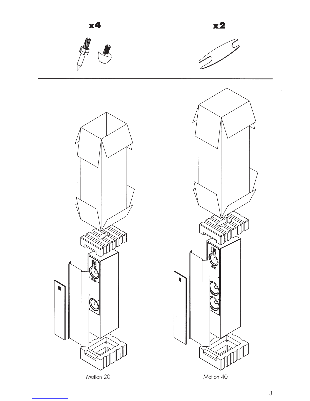
x4
x2
Motion
20
Motion
40
3
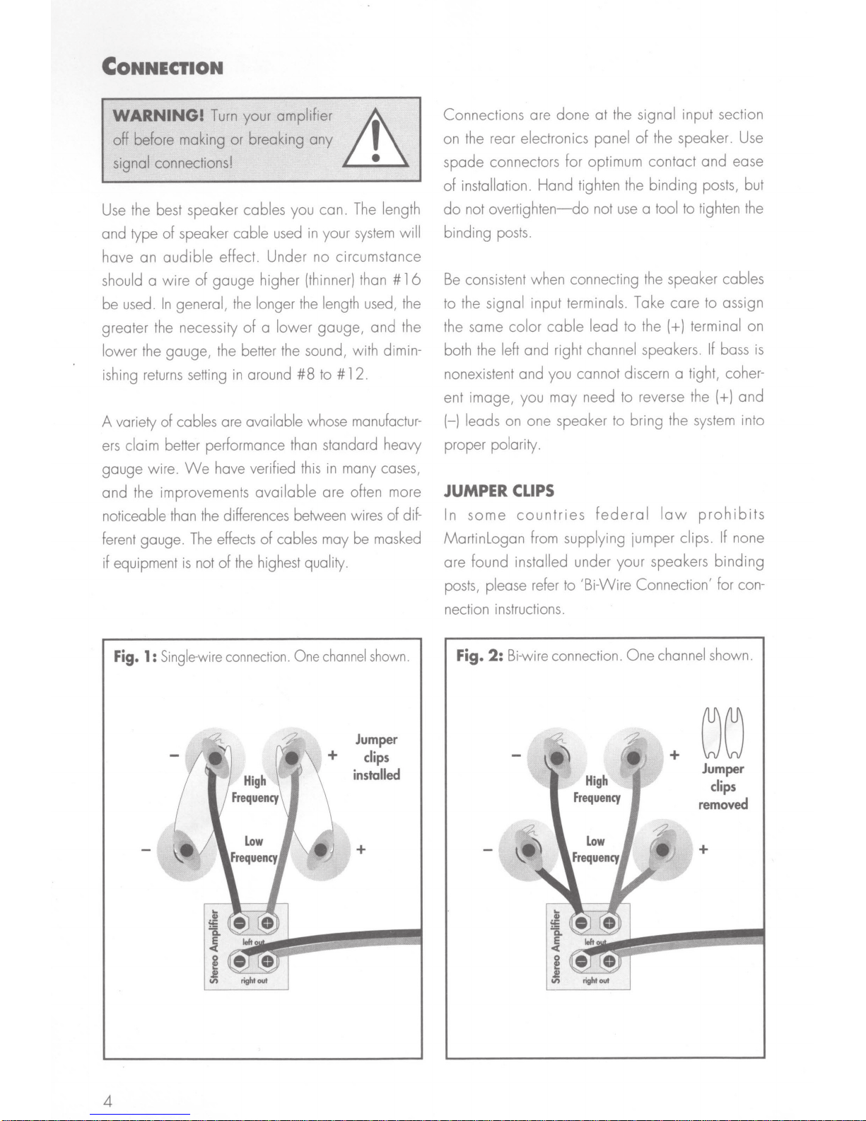
CoNNECTION
your amplifier
WARNING!
off before making or breaking
signal connections!
the best speaker cables you can.
Use
and type
have
should a
be used.
greater the necessity
lower the gauge/ the better
ishing
A variety
ers
gauge wire.
and
noticeable
ferent gauge.
if equipment
of
audible
an
wire
In
returns
of
claim better performance than standard heavy
the improvements
Turn
speaker cable
effect. Under no circumstance
gauge
of
general/
setting
cables are available whose manufactur-
have verified
We
differences between wires of dif-
the
than
effects of cables may be masked
The
of
not
is
used
higher (thinner) than #
longer
the
lower
a
of
the
around
in
the
#8
available
highest quality.
Lh
any
The
system
your
in
length used/
the
gauge/ and the
sound/ with dimin-
12.
to#
many cases/
in
this
are often more
I
•
length
will
16
the
at the signal input section
Connections are
on the rear electronics panel
spade
of
do
binding
Be
to the signal input terminals. Take care to assign
the same color
both the left and right channel speakers.
nonexistent and you cannot discern a tight/ coherent image/ you may need to reverse the
(-) leads on one speaker to bring the
proper polarity.
JUMPER
In
Martinlogan
are found installed under your speakers
posts/ please refer to /Bi-Wire Connection/ for con-
connectors for optimum contact
installation. Hand tighten
overtighten-do
not
posts.
consistent when connecting the speaker cables
CLIPS
some
done
the speaker.
of
binding posts/ but
the
a tool to tighten the
use
not
cable
countries
from supplying jumper clips.
lead to the
federal
(+)
law
Use
ease
and
terminal on
bass
If
and
(+)
system
prohibits
into
none
If
binding
is
Fig.
Single-wire
1:
connection.
One
channel
Jumper
installed
+
shown.
clips
nection instructions.
Bi-wire connection.
2:
Fig.
-<6-
•'
-«.
'-""
;
High
Frequency
Low
Frequency
channel shown.
One
+
iiJ
00
Jumper
clips
removed
+
4
SINGLE WIRE CONNECTION
Please take note
under the
high-frequency
crossover together. Leaving
the
(+)
binding post and
either
binding
wire
black(-)
WARNING!
clips
are removed may you connect
individual
from your amplifiers to the high-frequency and low-frequency signal input binding
posts.
the
Damage
jumper
clips
of
the jumper
posts. These
and
low-frequency sections
these
from your amplifier to either red
the
(-) wire from your amplifier to
binding post
Only
(Fig.
after jumper
clips
installed
clips
attach the
in
place, connect
1
).
Lh
I
runs
of
speaker
will
occur to your amplifiers if
are not removed.
cable
•
BI·WIRE CONNECTION
This
connection method replaces the jumper
installed
of
the signal carrying conductors
under
the
binding
speaker wire from your amplifier.
posts
with individual
from
This
the
amplifier to
doubles
of
clips
runs
the
speaker,
crossover to
the
To
bi-wire you
and remove the jumper clips.
wires to
(+)
nect to the high-frequency drivers.
a second
which connect
connect both
nals
on your amplifier.
both
(+)
(-) wires
as
a
parallel
PASSIVE
For
those that desire ultimate performance, these
speakers may be passively bi-amplified using the
existing internal passive crossover elements.
This
method takes the bi-wiring concept
further. You
thus
direct-coupling each portion of
the
amplifier.
must
first loosen the binding posts
the
upper
set
set
of
wires to the lower binding posts
to
the low-frequency
sets
of wires
wires
to
the
(+)
to
the
(-) amplifier terminals.
connection
BI
·AMPLIFICATION
will
have
Connect one
of binding
to
Please
amplifier terminals and both
(Fig
a
dedicated
posts
the appropriate termi-
take care to connect
.
2).
the
set
of
which con-
Then
connect
drivers. Next,
This
is
known
one
step
channel
of
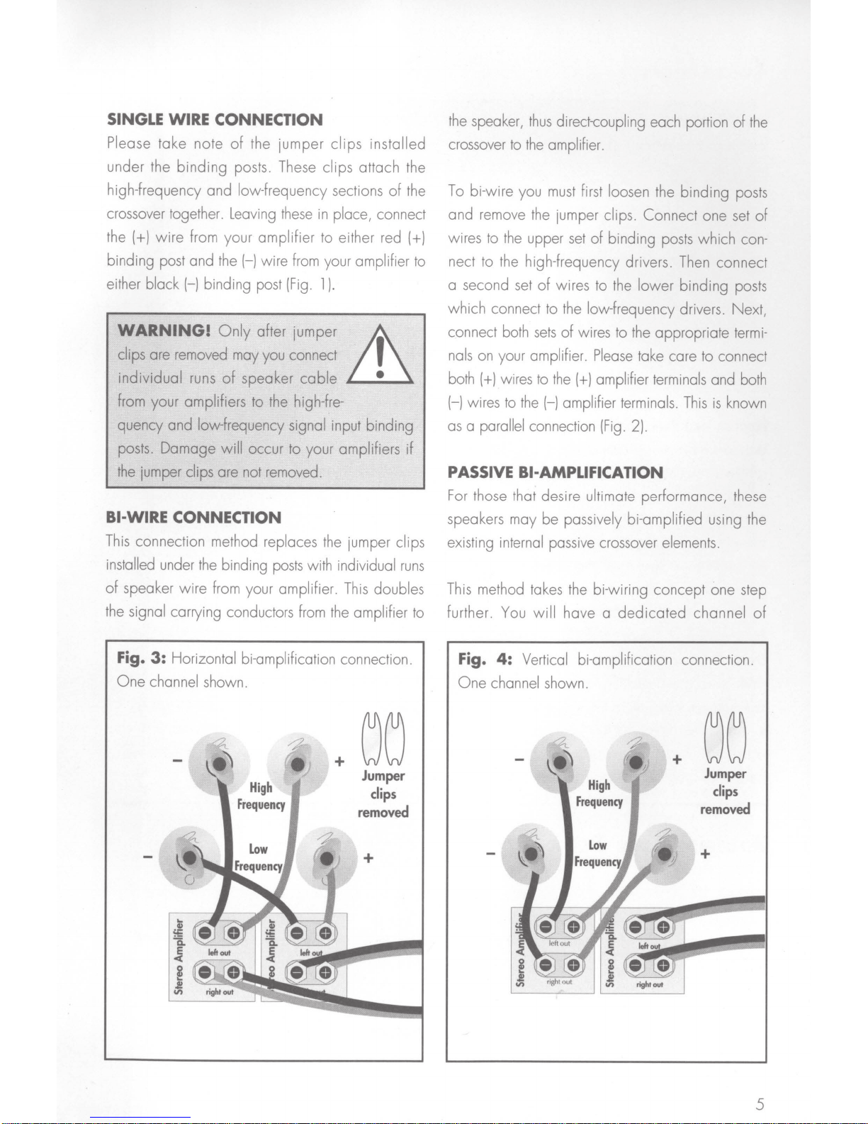
Fig. 3:
One
Horizontal bi-amplification connection.
channel shown.
~
Hi
gh
Frequency
GG
+
Jumper
clips
removed
Fig. 4:
One
channel shown.
Vertical bi-amplification connection.
+
Hi
gh
Frequency
Jumper
clips
removed
+
right
out
5
 Loading...