

MartinLogan Motion 35XT User Manual
user’s manual
WARNING!
• Refer servicing to a qualified
technician.
• To prevent fire or shock hazard,
do not expose this module to moisture.
• Turn amplifier off should any abnormal
conditions occur.
• Do not drive speaker beyond its rated power.
The lightning bolt flash with arrowhead
symbol, within an equilateral triangle,
is intended to alert the user to the pres-
ence of potentially “dangerous voltage” within the
product’s enclosure that may be sufficient to consti-
tute a risk of electric shock.
The exclamation point within an equi-
lateral triangle is intended to alert the
user to the presence of important oper-
ating and maintenance (servicing) instructions in the
literature accompanying the appliance.
Connection ............................ 4
Jumper Clips .......................4
Single Wire Connection ...............5
Bi-wire Connection ...................5
Passive Bi-amplification ................5
Active Bi-amplification .................6
Installation ............................. 7
Break In ..........................7
Installing On A Flat Surface .............7
Frequently Asked Questions ............... 7
Troubleshooting ........................ 8
Contacting Customer Service .............8
General Information ..................... 8
Warranty Information .................8
Serial Number ......................8
Service ..........................8
Specifications .......................... 9
Dimensional Drawings .................10
Serial Number:_____________________________
In accordance with the European Union
WEEE (Waste Electrical and Electronic
Equipment) directive effective August 13,
2005, we would like to notify you that this product
may contain regulated materials which upon dispos-
al, according to the WEEE directive, require special
reuse and recycling processing. For this reason Martin
Logan has arranged with our distributors in European
Union member nations to collect and recycle this prod-
uct at no cost to you.
To find your local distributor please contact the
dealer from whom you purchased this product, email
info@martinlogan.com or visit the distributor locator at
www.martinlogan.com.
Please note, only this product itself falls under the
WEEE directive. When disposing of packaging and
other related shipping materials we encourage you to
recycle these items through the normal channels.
Record your serial number here for easy reference.
You will need this information when filling out your
warranty registration. The serial number is located
near the binding posts and on the product carton.
2
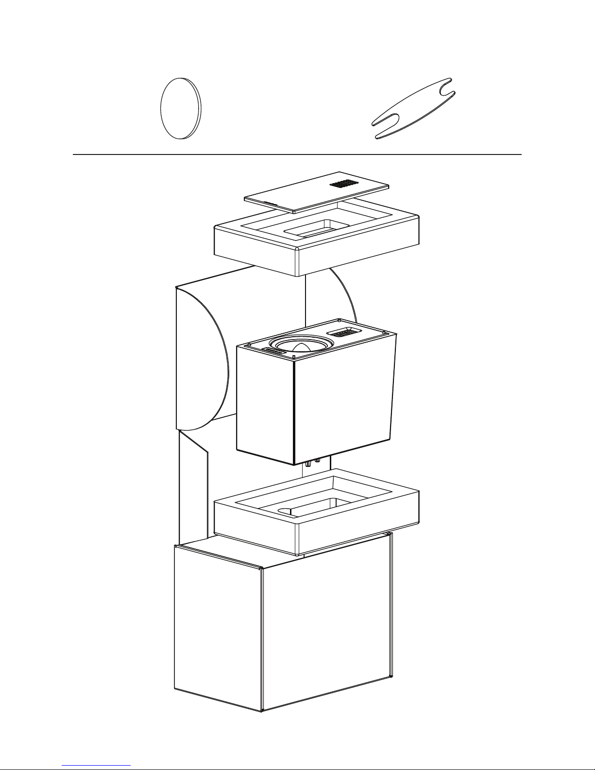
x2x4
3
CONNECTION
WARNING! Turn your amplifier
off before making or breaking any
signal connections!
Use the best speaker cables you can. The length
and type of speaker cable used in your system will
have an audible effect. Under no circumstance
should a wire of gauge higher (thinner) than #16
be used. In general, the longer the length used,
the greater the necessity of a lower gauge, and
the lower the gauge, the better the sound, with
diminishing returns setting in around #8 to #12.
A variety of cables are available whose manufacturers claim better performance than standard heavy
gauge wire. We have verified this in many cases,
and the improvements available are often more
noticeable than the differences between wires of different gauge. The effects of cables may be masked
if equipment is not of the highest quality.
Connections are done at the signal input section
on the rear electronics panel of the speaker. Use
spade connectors for optimum contact and ease
of installation. Hand tighten the binding posts, but
do not overtighten—do not use a tool to tighten the
binding posts.
Be consistent when connecting the speaker cables
to the signal input terminals. Take care to assign
the same color cable lead to the (+) terminal on
both the left and right channel speakers. If bass is
nonexistent and you cannot discern a tight, coherent image, you may need to reverse the (+) and
(–) leads on one speaker to bring the system into
proper polarity.
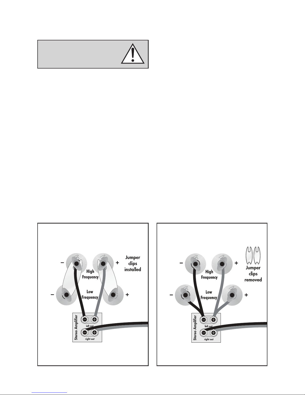
JUMPER CLIPS
In some countries federal law prohibits
MartinLogan from supplying jumper clips. If none
are found installed under your speakers binding
posts, please refer to ‘Bi-Wire Connection’ for connection instructions.
Fig. 1: Single-wire connection. One channel shown.
Fig. 2: Bi-wire connection. One channel shown.
4
 Loading...