

Page 1
Dynamotm 1000W | Dynamotm 700W | SWT-2
u s e r ’ s m a n u a l
Page 2
IMPORTANT SAFETY INSTRUCTIONS
1 Read these instructions.
2 Keep these instructions.
3 Heed all warnings.
4 Follow all instructions.
5 Do not use this apparatus near water.
6 Clean only with dry cloth.
7 Do not block any ventilation openings. Install in accordance with the
manufacturer's instructions.
8 Do not install near any heat sources such as radiators, heat registers,
stoves, or other apparatus (inlcuding amplifiers) that produce heat.
9 Do not defeat the safety purpose of the polarized or grounding-type
plug. A polarized plug has two blades with one wider than the other.
A grounding type plug has two blades and a third grounding prong.
The wide blade or the third prong are provided for your safety. If the
provided plug does not fit into your outlet, consult an electrician for
replacement of the obsolete outlet.
10 Protect the power cord from being walked on or pinched particu-
larly at plugs, convenience receptacles, and the point where they exit
from the apparatus.
11 Only use attachments/accessories specified by the manufacturer.
12 Use only with the cart, stand, tripod, brack-
et, or table specified by the manufacturer,
or sold with the apparatus. When a cart
is used use caution when moving the cart/
apparatus combination to avoid injury from
tip-over.
13. Unplug this apparatus during lightning storms or when unused for
long periods of time.
14. Refer all servicing to qualified service personnel. Servicing is required
when the apparatus has been damaged in any way, such as powersupply cord or plug is damaged, liquid has been spilled or objects
have fallen into the apparatus, the apparatus has been exposed to rain
or moisture, does not operate normally, or has been dropped.
15. WARNING: To reduce the risk of fire or electric shock, this apparatus should not be exposed to rain or moisture and objects filled with
liquids, such as vases, should not be placed on this apparatus.
16. To completely disconnect this equipment from the mains, disconnect
the power supply cord plug from the receptacle.
17. The mains plug of the power supply cord shall remain readily operable.
18 Do not expose this equipment to dripping or splashing and ensure
that no objects filled with liquids, such as vases, are placed on the
equipment.
In accordance with the European Union WEEE (Waste
Electrical and Electronic Equipment) directive effective
August 13, 2005, we would like to notify you that this
product may contain regulated materials which upon
disposal, according to the WEEE directive, require special reuse and
recycling processing.
For this reason MartinLogan has arranged with our distributors in
European Union member nations to collect and recycle this product at no
The lightning bolt flash with arrowhead symbol, within
an equilateral triangle, is intended to alert the user to
the presence of uninsulated “dangerous voltage” within
the product’s enclosure that may be of sufficient magnitude to constitute a risk of electric shock.
2
cost to you. To find your local distributor please contact the dealer from
whom you purchased this product, email info@martinlogan.com or visit
the distributor locator at www.martinlogan.com.
Please note, only this product itself falls under the WEEE directive.
When disposing of packaging and other related shipping materials we
encourage you to recycle these items through the normal channels.
The exclamation point within an equilateral triangle is
intended to alert the user to the presence of important
operating and maintenance (servicing) instructions in
the literature accompanying the appliance.
Page 3
Important Safety Instructions 2
Contents 3
Packaging 4
Introduction and Installation in Brief 6
Introduction
Installation in Brief
About the Controls 7
Connections and Control Settings 8
Before Connecting the Dynamo
2-Channel Mode
Multi-Channel/LFE Mode . . . . . . . . . . . . . . . . . . . 9
AC Power Connection . . . . . . . . . . . . . . . . . . . . 10
Replacing the Fuse
Break-In
Optional Wireless Connection
Placement 11
Listening Position
Ask Your Dealer
Enjoy Yourself
Installing in a Cabinet
Changing Woofer Orientation. . . . . . . . . . . . . . . 12
Room Acoustics 13
Your Room
Terminology
Solid Footing
Home Theater 14
FAQ & Troubleshooting 15
Frequently Asked Questions
Troubleshooting
Specifications 16
Dynamo 1000W Specifications
Dynamo 700W Specificaitons
General Information 17
Warranty and Registration
Service
Dimensional Drawings 17
SWT-2 Dimensional Drawings
Dynamo 1000W Dimensional Drawings . . . . . . . . 18
Dymamo 700W Dimensional Drawings . . . . . . . . 19
Serial Numbers: _______________
Record your serial numbers here for easy reference. You will need this information when filling out your warranty registration. Your serial number is located
near the bottom of the backplate and on the shipping container.
Dynamo 1000W
Dynamo 700W
Tested to Comply
with FCC Standards
FOR HOME OR OFFICE USE
This device complies with part 15
of the FCC Rules. Operation is
subject to the following two conditions: (1) This device may not
cause harmful interference, and
(2) this device must accept any
interference received, including
interference that may cause undesired operation.
WARNING!
• Hazardous voltages exist inside—do not
remove cover.
• Refer servicing to a qualified technician.
• To prevent fire or shock hazard, do not
expose this module to moisture.
• Unplug subwoofer should any abnormal
conditions occur.
WARNING! Do not use your Dynamo 1000W or Dynamo 700W subwoofers or SWT-2 transmitter outside of the
country of original sale—voltage requirements vary by country. Improper voltage can cause damage that will be potentially expensive to repair. The Dynamo 1000W or Dynamo 700W subwoofers and SWT-2 transmitter are shipped to
authorized MartinLogan distributors with the correct power supply for use in the country of intended sale. A list of authorized distributors can be accessed at www.martinlogan.com or by emailing info@martinlogan.
3
Page 4
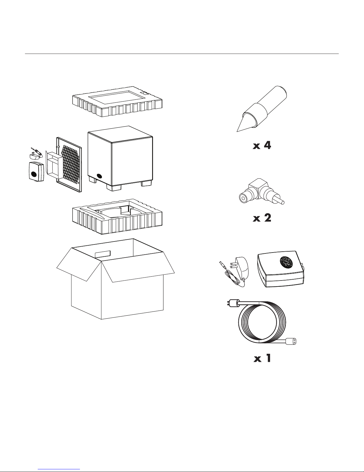
Packaging
4 Packaging
Page 5

Thank you—the MartinLogan owner,
for loving what we do,
and
making it possible for us to do what we love.
55
Page 6

introduction and installation in Brief
Introduction
Congratulations! You have invested in one of the
world's premier subwoofers.
The MartinLogan Dynamo 1000W and 700W
subwoofers represent the extension of an intensive,
dedicated team research program directed toward establishing a world class line of reference subwoofers using
leading-edge technology, without compromising durability, reliability, craftsmanship or aesthetics.
These subwoofers use high-excursion drivers to achieve
deep, tight, well-defined bass. A proprietary amplifier is
used to drive the output stage with precision and extremely
high efficiency. Low-pass filtering and phase control have
been designed to make integrating the Dynamo 1000W
and Dynamo 700W subwoofers with MartinLogan and
non-MartinLogan products both seamless and simple.
The materials in your new subwoofer are of the highest
quality and will provide years of enduring enjoyment and
deepening respect. The cabinet is constructed from the
finest composite material for acoustical integrity and is finished with an attractive custom coating.
This User's Manual will explain in detail the operation of
your subwoofer and the philosophy applied to its design.
A clear understanding will insure that you obtain maximum performance and pleasure from this most exacting
subwoofer.
Should you encounter a persistent problem that cannot
be resolved, please contact your authorized MartinLogan
dealer. They will provide you with the appropriate technical analysis to alleviate the situation.
Step 1: Unpacking
Remove your new subwoofer from its packing.
Step 2: Placement
Ideally, place the subwoofer in a corner near the front of the
room. This is a good place to start. Please see the Placement
section (page 11) of this manual for more details.
Step 3: Signal Connection
The Dynamo 1000W and Dynamo 700W subwoofers
are provided with the SWT-2 subwoofer wireless transmitter. We recommend using a physical wire connection
if possible. However, if ideal subwoofer placement is a
challenge the SWT-2 will provide a seamless wireless
connection with an extremely detailed and articulate bass
performance.
Use the best cables you can. High quality cables, available
from your specialty dealer, are recommended and will
give you superior performance.
Attach your preamplifier/processor outputs through cables
to the signal input area located on the subwoofer’s rear
panel. Please see the Connections and Control Settings
section (pages 8–10) of this manual for more details.
Installation in Brief
We know that you are eager to hear your new subwoofer,
so this section is provided to allow fast and easy
you have it operational, please take the time to
the rest of the information in this manual. It will give you perspective on how to attain the greatest possible performance
from this most exacting subwoofer system.
If you experience any difficulties in setup or operation
of the subwoofer, please refer to the Placement, Room
Acoustics and Connections and Control Settings sections.
6 Introduction and Installation in Brief
set up. Once
read, in depth,
Step 4: Power Connection (AC) (see warning)
Make sure the level knob is set at 'Min'. Plug the
subwoofer into a wall outlet. Review the AC Power
Connection section (page 10) of this manual for more
details.
Step 5: Setting the Controls
Set the level knob to a medium volume position (12
o'clock). Set the power switch to ‘Auto On'.
Step 6: Listen and Enjoy
Now, you may adjust your system and enjoy!
Page 7
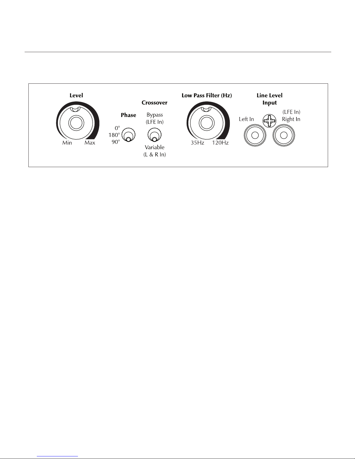
Figure 1. Dynamo 1000W and Dynamo 700W controls.
aBout the controls
Level Knob
Setting the level too high will cause the bass to seem bloated and is the single most common cause of bad sounding
subwoofers. A rule of thumb is that the subwoofer should
not draw attention to itself, but should simply make the systems low end seem more extended and accurate.
Phase Control Switch
The phase control is entirely dependent on the size and
configuration of your listening environment, the placement
of the unit, and your seating arrangement. Due to the way
bass sound waves develop in different rooms, there is
no rule of thumb for setting phase. For instance, if your
room has a peak at the subwoofer crossover area, you
may wish to set the phase so the actual acoustic outputs
of the subwoofer and main speakers are out of phase.
Experiment, try different settings and be patient.
Crossover
When the subwoofer is connected in multi-channel mode
(via LFE), the crossover switch should be set to 'Bypass (LFE
In)' so that the low pass filter is not active and your processor handles the bass management.
When connected in 2-channel mode (via left/right input),
the crossover switch should be set to 'Variable (L&R In)' so
that the low-pass filter is active.
Low Pass Filter Knob
When the subwoofer is connected in multi-channel mode
(via LFE), the low pass filter is not active and your proces-
sor handles the bass management. When connected in
2-channel mode via its left/right input, the low-pass filter
is active.
As a general rule the low pass filter should be set equal
to approximately 70% of your speaker’s lowest frequency
response. Remember, this is a general rule. We advise
that once you try the recommended setting using the formula above, you should try the surrounding settings to see
which sounds best.
Wireless Sync Button and Status LED (not shown above)
The wireless sync button is used to establish connection to
the SWT-2 MartinLogan Subwoofer Wireless Transmitter.
The Wireless status LED indicates the current status of the
wireless connection (see page 10 for further details).
Status LED (not shown above)
When the status LED (located on the back of the
subwoofer) is blue, the subwoofer is on. When the status
LED is red the subwoofer is in standby mode.
Master Power Switch (not shown above)
Located on the back panel of the subwoofer, the Master
Power switch must be set to 'Auto On' for the subwoofer
to operate. When set to 'Auto On' the subwoofer will
automatically enter a power saving mode when no audio
signal is detected. The subwoofer will automatically come
out of power saving mode when a signal is detected.
About the Controls 7
Page 8
connections and control settings
Before Connecting the Dynamo
MartinLogan's engineering and design team developed
the Dynamo 1000W and Dynamo 700W subwoofers
for easy setup and system integration. Before beginning
to connect your subwoofer, please review the controls
discussed in the last section. An understanding of these
will help speed you along as you connect and integrate
your subwoofer with your system. All signal connections
are done on the rear connections panel of the subwooferMake certain that all of your connections are tight.
WARNING! Turn your subwoofer to 'Off'
before making or breaking any signal connections!
2-Channel Mode
This setup is recommended if your subwoofer will be used
in a 2-channel system with main speakers playing full
range. When a signal is connected via left/right inputs
and the crossover switch is set to 'Variable (L&R In), the
subwoofer's internal low pass filter is active.
If you will be using your system for both 2-channel and
multi-channel listening we recommend connecting the
subwoofer as recommended in 'Multi-Channel/LFE Mode'
on the next page. Some modern receivers and processors
allow users to route left and right channel low-frequency information, in addition to discrete LFE information,
through the LFE output.
4 Try the phase control in different settings until the
best blending is obtained. If you are augmenting
MartinLogan loudspeakers, we suggest you start with
the phase set at 90°.
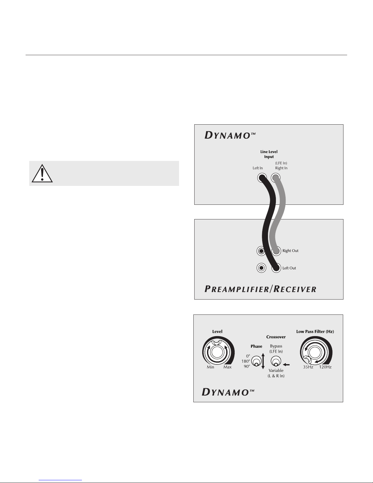
Figure 2. Signal connection for 2-channel mode.
Signal Connection (see figure 2):
1 Connect the left and right outputs of your preamplifier
to the left and right inputs using quality RCA interconnects. If your preamplifier only has one set of outputs
you may need to obtain Y adapters from your dealer.
Recommended Control Settings (see figure 3):
1
Set the crossover switch to 'Variable (L&R In)'
2
Set the 'Low Pass Filter' knob to approximately
your loudspeakers lowest frequency response.
3 While playing music with bass content, turn the level
control up until the music has deep extended bass,
being careful to avoid levels that become overwhelming.
8 Connections and Control Settings
.
70% of
Figure 3. Control settings for 2-channel mode.
Page 9
Multi-Channel/LFE Mode
This setup is recommended if your subwoofer will be used
in a dedicated home theater or multi-channel system. When
a signal is connected to the subwoofer’s LFE input, and the
crossover switch is set to 'Bypass (LFE In)' the internal low pass
filter is not active. By following this setup, you will allow your
processor to handle most of the bass management.
If you will be using your system for both 2-channel and
multi-channel listening we recommend using this setup
and connection method. Some modern receivers and
processors allow users to route left and right channel
low-frequency information, in addition to discrete LFE information, through the LFE output.
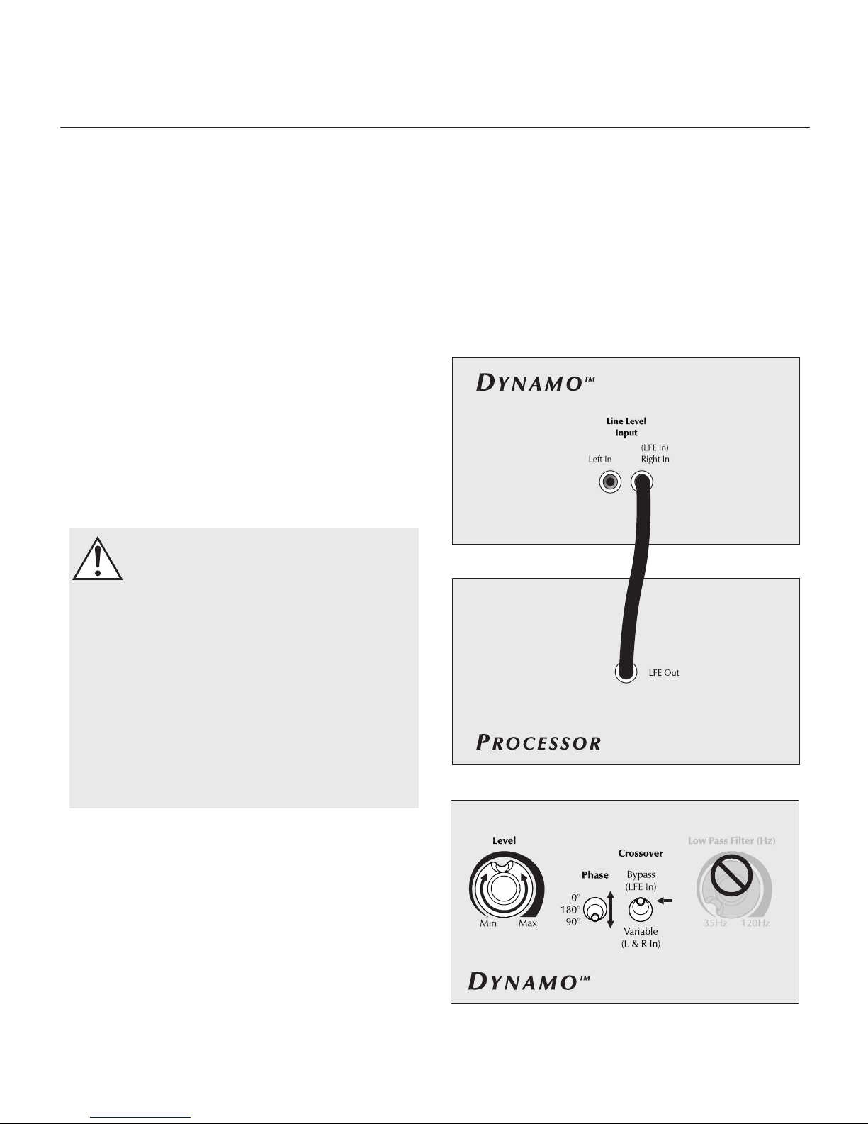
Signal Connection (see figure 4):
1 Connect the LFE output of the processor to the LFE input
using a quality RCA interconnect.
WARNING!
Based on the performance of most processors, it is recommended that MartinLogan
center and effects type speakers not be run
in large, wide, or full range mode. Doing
so may potentially damage the speaker if
the processor attempts to drive the speaker
beyond its rated frequency range. This
warning also applies to products from other
manufacturers.
Pass: 24dB. The optimal setting for these options may vary
depending on your room and listening preferences.
4 Adjust the phase control until ideal blending is obtained. If
you hear no discernible difference leave the phase at 0°.
5 Follow the instructions in your processor manual to fine-
tune the subwoofer level
It is recommended to run center and effects
type speakers in limited or narrow mode.
Some processors have an option to route the LFE
channel to your main and/or surround speakers.
We recommend that you do not use this option.
Recommended Control Settings (see figure 5):
1
Set the crossover switch to 'Bypass (LFE In)'
2 Use the bass management section of your processor‘s
speaker level setup option to set the subwoofer level at an
appropriate level. Follow the instructions in your processor
manual to fine-tune the subwoofer level.
3 If your processor offers the option to setup crossovers for a
subwoofer, we recommend that you start with the following
settings—Crossover: 70Hz, High-Pass: 12dB, and Low-
Figure 4. Signal connection for multi-channel mode.
.
Figure 5. Control settings for multi-channel mode.
Connections and Control Settings 9
Page 10
AC Power Connection
WARNING! The power cord should not be
installed, removed, or left detached from
the subwoofer while the other end is connected to an AC power source.
The IEC power cord should be firmly inserted into the AC
power receptacle on the rear connection panel of the
subwoofer, then to any convenient AC wall outlet. The sub
also integrates a signal sensing power supply that automatically switches off after sensing no music signal for several
minutes (this will occur when the power switch is set to 'Auto').
Your subwoofer is wired for the power service supplied in
the country of original consumer sale. The AC power rating applicable to a particular unit is specified both on the
packing carton and on the serial number plate attached to
the subwoofer.
If you remove your subwoofer from the country of original
sale, be certain that AC power supplied in any subsequent
location is suitable before connecting and operating the
subwoofer. Substantially impaired performance or severe
damage may occur to the subwoofer if operation is attempted from an incorrect AC power source.
1. Press the subwoofer’s sync button and hold for 3 seconds. The LED will blink quickly.
2 Press the sync button on the SWT-2 transmitter and hold
for 3 seconds. The LED will blink quickly. If pairing has
completed successfully both LEDs will stop blinking and
remain on. Please note: If a link is not established
after 30 seconds this transmitter’s LED will start blinking
slowly. Repeat both steps.
WARNING! For best performance we recommend that
the SWT-2 wireless transmitter not be placed on the floor.
WARNING! When operating wirelessly this subwoofer
may be susceptible to RF interference in the 2.4GHz
bandwidth from microwave ovens and wireless devices
such as WiFi systems, video game consoles, cordless
telephones, blue tooth devices, and baby monitors.
Generally, this issue (intermittent sound or slight popping
noises) is easily resolved by physically separating problematic devices from one another—a distance as little as
two feet will often alleviate the interference. In the case of
microwave ovens, the interference will only occur when
the microwave is operating.
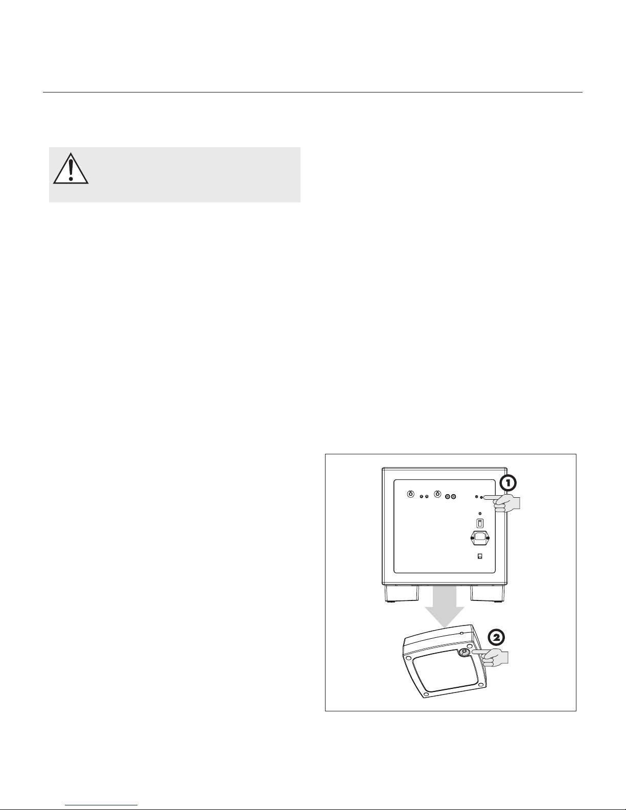
Replacing the Fuse
If the fuse in your subwoofer should require changing, turn
off and unplug your subwoofer before removing the fuse.
Replace with a matching fuse.
Break-In
Our custom made woofers require approximately 50 hours
of break-in at moderate listening levels before their optimal
performance occurs. This will factor in on any critical listening and judgment.
Optional Wireless Connection
The Dynamo 1000W and 700W subwoofers incorporate
a wireless receiver for use with the MartinLogan SWT-2
Subwoofer Wireless Transmitter. To establish a wireless
connection, connect a transmitter to your electronics and
follow these two easy steps.
10 Connections and Control Settings
Figure 6. Establishing a connection between the subwoofer and the
SWT-2 Subwoofer Wireless Transmitter (included).
Page 11
Listening Position
Generally, subwoofers have the most output when placed
in the corner of a room. However, this can also exaggerate the subwoofers output making blending difficult. We
recommend starting by placing the subwoofer in a corner. If, after the full range of tuning techniques have been
employed, the subwoofer sounds like it has too much upper
bass energy try pulling it away from the wall, toward the
listening position. This will lessen the reinforcement of these
problematic frequencies from the wall and likely smooth out
the response. Repeat the tuning techniques with the woofer
controls after you move it (see figure 7).
Ask Your Dealer
Your MartinLogan dealer can suggest many options for
optimal subwoofer placement. They also have many tools
at their disposal, such as experience, familiarity with the
associated equipment, and even sound analysis equipment
which may make the task of determining optimal subwoofer
placement easier.
Enjoy Yourself
Placement
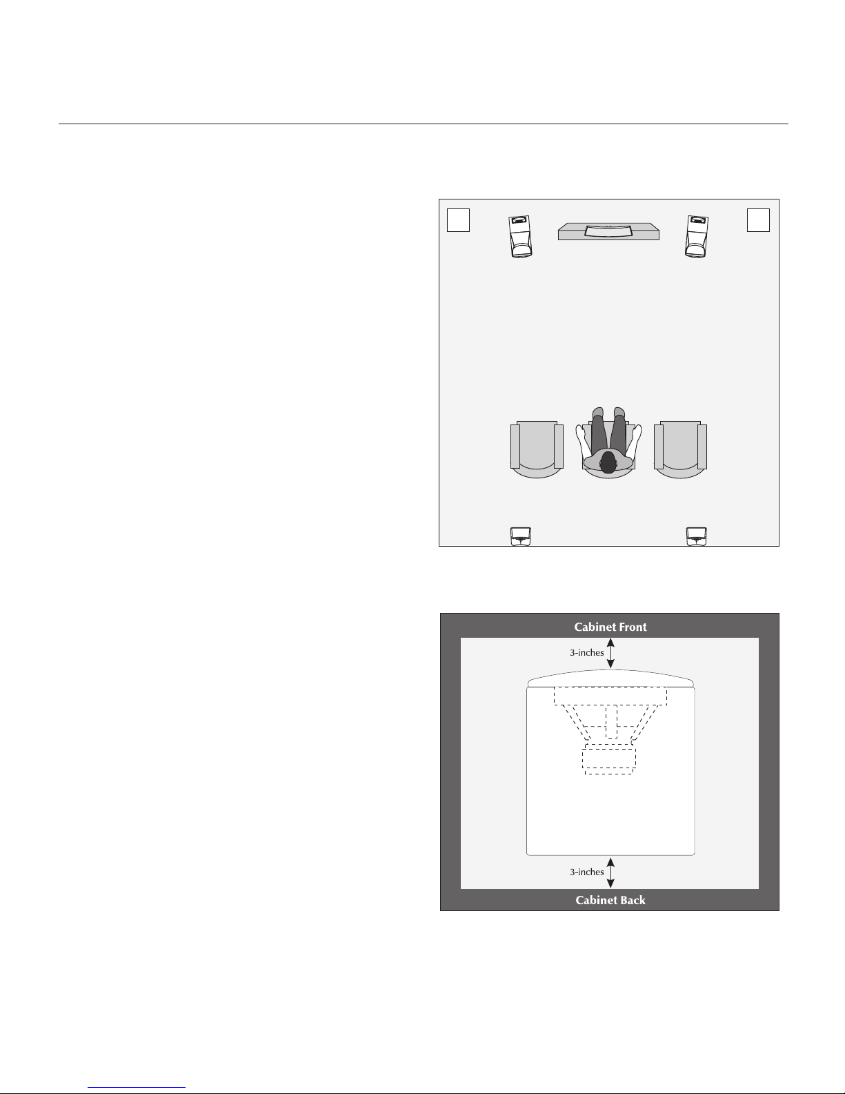
Figure 7. Dynamo subwoofers as the LFE (effects) channels, MartinLogan
speakers as front, center, and surround (effects) channels. Note the corner
placement of the subwoofers at the front of the listening room.
The Dynamo 1000W and Dynamo 700W are very
refined subwoofers and will benefit from care in setup.
With the above placement tips in mind you will find, over
months of listening, that small changes can result in measurable differences. As you live with your subwoofer, do
not be afraid to experiment with positioning until you find
the optimal relationship between your room, settings and
subwoofer that gives you the best results. Your efforts will
be rewarded.
Installing in a Cabinet
When placing the subwoofer inside of a cabinet it is recommended that there be a minimum of three inches of open
space between the cabinet and the front and back sides
(see figure 8).
Figure 8. Placing the subwoofer in a cabinet requires a minimum of three
inches of open space on the front and back.
Placement 11
Page 12
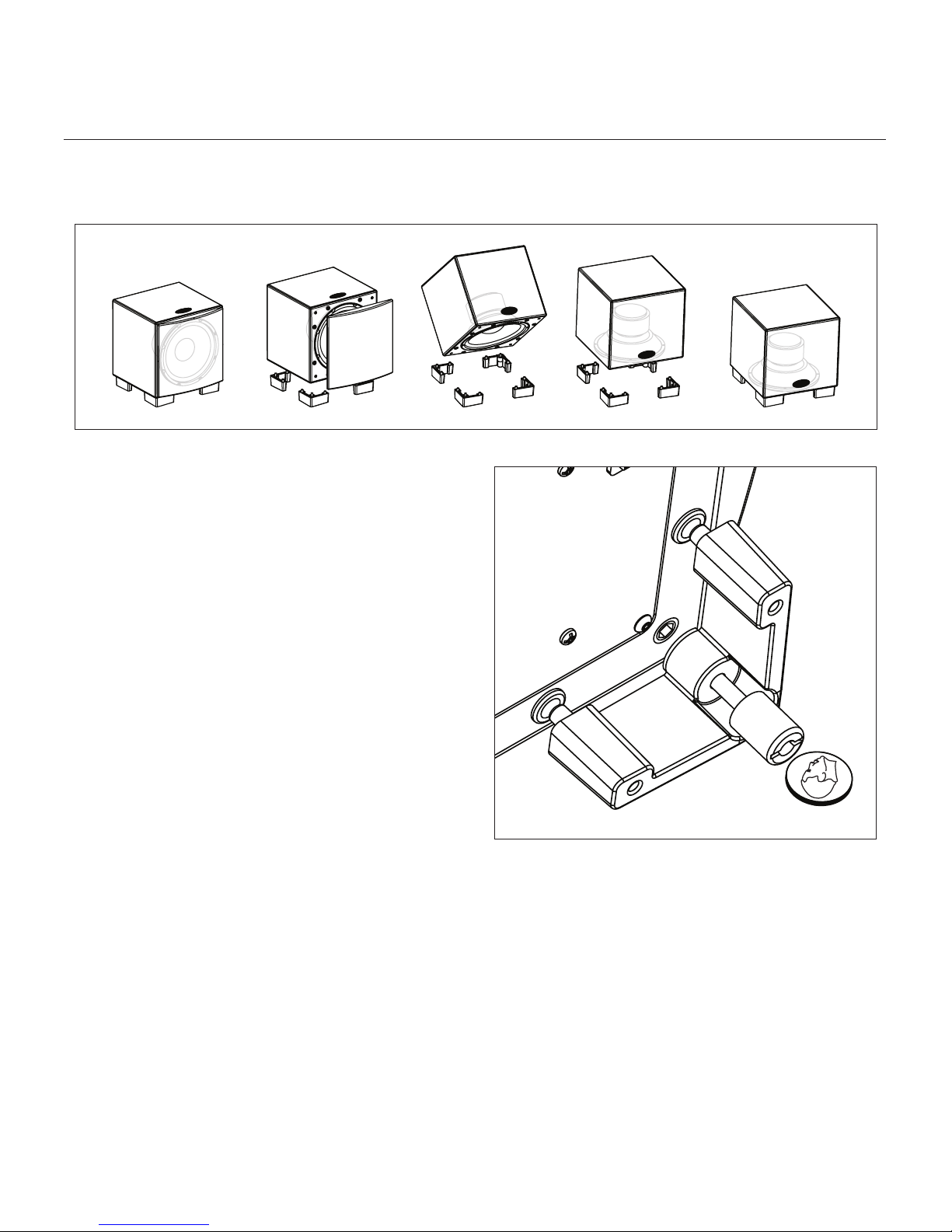
Figure 9. The Dynamo 1000W and Dynamo 700W are capable of both front-firing and down-firing woofer orientations.
Changing Woofer Orientation
When installing the subwoofer in a cabinet it is recommended that the subwoofer be converted to a front firing
configuration. (see figure 9).
1
Prepare a flat surface with a blanket to protect the finish.
Unplug signal and power connections. Remove the grill
cloth.
2 Carefully lay the subwoofer on its side. Using a coin,
unscrew the attached feet. (see figure 10).
3
Change the location of the four feet.
4 Using a coin, reinstall the feet (see figure 10).
Please note, 90° RCA adaptors may be required to
make signal connections. Two 90° RCA adaptors are
included with the subwoofer.
Figure 10. To change woofer orientation, use a coin to unscrew the
attached feet, change location, and reinstall.
12 Placement
Page 13

Your Room
room acoustics
This is an area that requires both a little background to
understand and some time and experimentation to attain
the best performance from your system. Your room is actually a component and an important part of your system.
This component is a large variable and can dramatically
add to or subtract from a great sonic experience.
All sound is composed of waves. Each frequency has its
own wave size, with the lower, or bass frequencies literally encompassing from 10 feet to as much as 40 feet. Your
room participates in this wave experience like a swimming pool with waves reflecting and becoming enhanced
depending on the size and shape of the room and the
types of surfaces in the room.
Remember that your audio system can actually generate all
of the information required to recreate a sonic event in time,
space, and tonal balance. Acoustically, the role of an ideal
room would be to neither delete nor contribute to that information. However, nearly every room does to some degree.
Terminology
Standing Waves
Sound coming from a speaker bounces around in a room
until a pattern emerges—this is called a standing wave.
Typically, this is only a problem with frequencies below
100Hz. When this happens different parts of your room
experience either an excess or a lack of bass.
Some people believe that having a room without parallel
walls will eliminate this effect. The truth is that non-parallel
walls only generate different standing wave patterns than
those that occur in rectangular rooms.
with the music, and may contribute in a negative way to
the sound. Ringing, boominess, and even brightness can
occur simply because surfaces and objects are "singing
along" with your speakers.
Resonant Cavities
Small alcoves or closet type areas in your room can be
chambers that create their own "standing waves" and can
drum their own "one note" sounds.
Solid Footing
After living and experimenting with your subwoofer,
you may want to use ETC™ (Energy Transfer Coupler)
Spikes (see figure 11). With the use of these spikes,
the subwoofer will become more firmly planted on the
floor and, consequently, bass will tighten. It is best not
to implement the spikes, however, until you are secure in
the positioning, as the spikes can damage the floor if the
subwoofer is moved.
Spike Installation Instructions:
1 Carefully lay the subwoofer on its side to gain access
to the bottom of the feet.
2 Firmly press the spikes into the feet.
Caution: Make sure your hands and any cabling are
clear of the spikes. Do not slide the subwoofer as spikes
are sharp and can damage your floor or carpet.
Usually, you can excite most of the standing waves in
a room by putting the subwoofer in a corner. Listening
position determines which standing waves you will experience. For instance, if you sit in a corner you will hear
most of the standing waves. This can be an overpowering
experience. Sitting next to a wall can also intensify the
levels of the standing waves that are experienced.
Resonant Surfaces and Objects
All of the surfaces and objects in your room are subject to
the frequencies generated by your system. Much like an
instrument, they will vibrate and "carry on" in syncopation
Figure 11. To install the spikes, press them into the feet.
Room Acoustics 13
Page 14
home theater
It had long been the practice of stereo buffs to connect their
television to a stereo system. The advantage was the use
of the larger speakers and more powerful amplifier of the
stereo system. Even though the sound was greatly improved, it
was still mono and limited by the broadcast signal.
In the late 1970’s and early 1980’s two new home
movie formats became widely available to the public:
VCR and laser disc.
By 1985, both formats had developed into very high quality
audio/video sources. In fact, the sonic performance of some
video formats exceeded audio-only formats. Now, with
theater-quality sound available at home, the only element
missing was the "surround sound" presentation found in
movie houses.
Fortunately, Dolby and DTS encoded DVD’s emerged
with the same surround sound information encoded on
home releases as the theatrical release. Additionally,
new high-resolution home-viewing formats such as Blu-ray
as well as high-definition content provided via cable or
satellite have evolved which include multi-channel encoded audio that is virtually master tape quality. All that is
required to retrieve this information is a decoder and additional speakers and amps to reproduce it.
speaker, and that it is recommended for use as a center
speaker. This is not the place to cut corners.
Surround Speakers
We recommend (along with the film industry) that the surround speakers play down to at least 80 Hz. Surround
speakers contain the information that makes it appear that
planes are flying over your head. Some may suggest that
this is the place to save money and purchase small, inexpensive speakers. If you choose to do so, be prepared
to upgrade in the future as discrete multi-channel digital
encoding is proliferating rapidly and the demands on surround speakers have increased.
Subwoofer
With any good surround system you will need one or
more high-quality subwoofers (the .1 in a 5.1, 6.1, or 7.1
channel surround system). Most movie soundtracks contain
large amounts of bass information as part of the special
effects. Good subwoofers will provide a foundation for the
rest of the system.
Home theater is a complex purchase and we recommend
that you consult your local MartinLogan dealer, as they
are well versed in this subject.
Each piece of a surround system can be purchased separately. Take your time and buy quality. No one has ever
complained that the movie was too real. The following list
and descriptions will give you only a brief outline of the
responsibilities and demands placed on each speaker.
Front Left and Front Right
If these speakers will be the same two used for your stereo
playback, they should be of very high quality and able to play
loudly (over 102 dB) and reproduce bass below 80 Hz.
Center Channel
This is the most important speaker in a home theater
system, as almost all of the dialogue and a large portion of the front speaker information is reproduced by the
center channel. It is important that the center speaker
be extremely accurate and mate well with the front
14 Home Theater
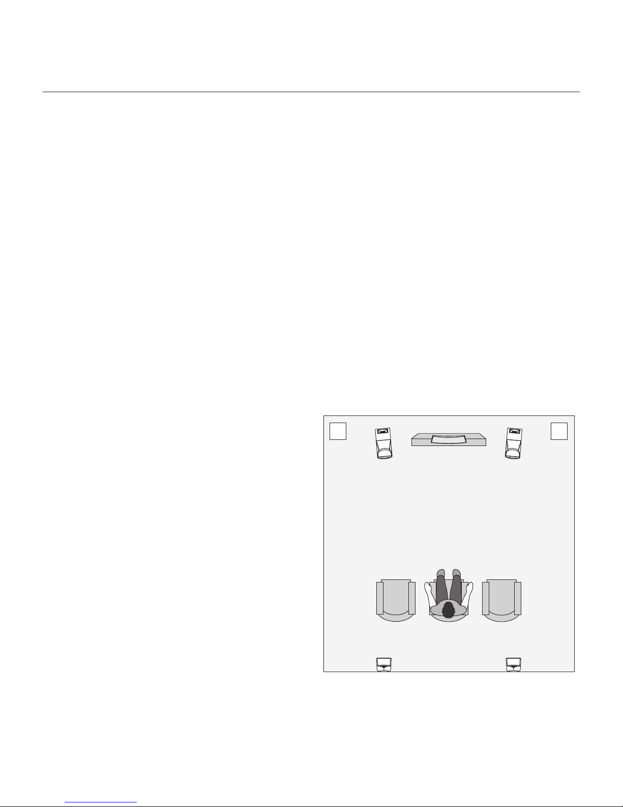
Figure 12. Dynamo subwoofers as the LFE (effects) channels, MartinLogan
speakers as front, center, and surround (effects) channels.
Page 15

faQ & trouBleshooting
Frequently Asked Questions
How do I clean my subwoofer?
Use a dust free cloth or a soft brush to clean your subwoofer.
We recommend a specialty cloth (available through the
Xtatic shop at www.martinlogan.com) that cleans better than
anything else we have tried.
Is it safe to set things on my subwoofer?
While your subwoofer is designed with a durable, stainresistant surface, we advise you not to set anything on your
subwoofer—especially containers holding liquids.
Is there likely to be any interaction between
my subwoofer and the television in my Audio/
Video system?
Yes. The subwoofer doesn’t use a shielded driver. We
recommend 3 feet between the subwoofer and video
components that are susceptible to magnetic fields..
Plamsma, LCD, and LED television are not suceptible to
magnetic interference.
Is there likely to be any interaction between
my subwoofer and other electrical devices in
my house?
yes. When operating wirelessly this subwoofer may be
susceptible to RF interference in the 2.4GHz bandwidth
from microwave ovens and wireless devices such as
WiFi systems, video game consoles, cordless telephones,
blue tooth devices, and baby monitors. Generally, this
issue (intermittent sound or slight popping noises) is easily resolved by physically separating problematic devices
from one another—a distance as little as two feet will
often alleviate the interference. In the case of microwave
ovens, the interference will only occur when the microwave is operating.
Will my electric bill go 'sky high' by leaving my
subwoofer plugged in all the time?
No. When the power switch is set to ‘Auto On’ the
subwoofer will draw about 15 watts when idle and only
1 watts in standby mode.
Should I unplug my subwoofer during a thunderstorm?
Yes, or before. It's a good idea to disconnect all of your
audio/video components during stormy weather.
Troubleshooting
No Output
• Check that all your system components are turned on.
• Check that the master power switch adjacent to the AC
receptacle is set to 'Auto On'.
• Check your wires and connections.
• Check all interconnecting cables.
• Make sure the level control is not turned down.
• Turn off and unplug the subwoofer and check the fuse
near the AC power cord receptacle on the back. If the
fuse has blown, replace the bad fuse with a matching
fuse.
• If the problem persists, contact your dealer.
Muddy Bass
• Check placement. Try moving the subwoofer closer to
the front and side walls.
• Check the type of feet that are being used. Try installing
the ETC spikes.
• Decrease the level.
• Check your processor setup.
• If the problem persists, contact your dealer.
Hums or Unusual Sounds
• Turn the subwoofer off, unplug all signal inputs, turn the
subwoofer back on and turn up the level. If the problem
disappears, the hum is originating elsewhere in your
system.
• Connect the subwoofer’s AC connection to the same AC
circuit as the pre amp.
• If operating in wireless mode, move the subwoofer
away from microwave ovens and/or any devices that
use wireless technology.
• If the problem persists, contact your dealer.
Intermitent Output With Wireless
• Make sure that no other wireless devices are within 2
feet of the SWT-2 transmitter.
• Check placement and make sure the SWT-2 wireless
transmitter is at least 1 foot off of the ground.
• Move the SWT-2 transmitter and sub closer together.
• Remove barriers from between the devices. Although
the SWT-2 uses an RF signal, it may not penetrate
some walls or cabinetry.
Frequently Asked Questions & Troubleshooting 15
Page 16

sPecifications
Dynamo 700W SpecificationsDynamo 1000W Specifications
The Dynamo 1000W subwoofer system consists of a
single woofer for high SPL output with minimal distortion.
The equalization used is specifically designed to counteract the response of the woofers sealed box response. This
equalization leads to minimal group delay and proper
transient response.
System Frequency Response
22–200 Hz ± 3 dB. Anechoic in LFE mode.
Low Pass Filter Frequencies
35Hz–120Hz
Low Pass Filter Switch
Bypass (LFE In), Variable (L&R In)
Phase
0°, 90°, 180°
Components
12” (30.5cm) high-excursion, polypropylene cone with
extended throw driver assembly; sealed non-resonant cabinet design
Amplifier
500 watts RMS (1000 watts peak)
The Dynamo 700W subwoofer system consists of a single
woofer for high SPL output with minimal distortion. The
equalization used is specifically designed to counteract
the response of the woofers sealed box response. This
equalization leads to minimal group delay and proper
transient response.
System Frequency Response
24–200 Hz ± 3 dB. Anechoic in LFE mode.
Low Pass Filter Frequencies
35Hz–120Hz
Low Pass Filter Switch
Bypass (LFE In), Variable (L&R In)
Phase
0°, 90°, 180°
Components
10” (25.4cm) high-excursion, polypropylene cone with
extended throw driver assembly; sealed non-resonant cabinet design
Amplifier
300 watts RMS (600 watts peak)
Impedance
Left & Right/LFE RCA – 20,000 Ohms
Inputs
Left & Right/LFE RCA Line Level
Weight
34 lbs. each (15.4 kg)
Mains Power Draw
Standby: 1W
Idle: 15W
Max: 650W
Size (Front-Firing Orientation)
13.69 inches W x 14.35 inches D x 15.46 inches H
(34.8cm W x 36.4cm D x 39.3cm H)
Size (Down-Firing Orientation)
13.69 inches W x 14.59 inches D x 14.54 inches H
(34.8cm W x 37.1cm D x 36.93cm H)
16 Specifications
Impedance
Left & Right/LFE RCA – 20,000 Ohms
Inputs
Left & Right/LFE RCA Line Level
Weight
26.5 lbs. each (12 kg)
Mains Power Draw
Standby: 1W
Idle: 15W
Max: 400W
Size (Front-Firing Orientation)
11.69 inches W x 12.31 inches D x 13.47 inches H
(29.7cm W x 31.3cm D x 34.2cm H)
Size (Down-Firing Orientation)
11.69 inches W x 12.53 inches D x 12.54 inches H
(29.7cm W x 31.8cm D x 31.9cm H)
Page 17

general information and sWt-2 dimensional draWings
Warranty and Registration Service
Your Dynamo subwoofer is provided with an automatic
Limited 90 Day Warranty coverage.
You have the option, at no additional charge, to receive
Limited 3-Year Warranty coverage. To obtain the Limited
3-Year Warranty coverage you need to complete and
return the Certificate of Registration, included with your
subwoofer, and provide a copy of your dealer receipt, to
MartinLogan within 30 days of purchase.
For your convenience MartinLogan also offers online warranty
registration at www.martinlogan.com.
MartinLogan may not honor warranty service claims unless
we have a completed Warranty Registration card on file!
If you did not receive a Certificate of Registration with your
new subwoofer you cannot be assured of having received
a new unit. If this is the case, please contact your authorized MartinLogan dealer.
SWT-2 Dimensional Drawings
Should you be using your MartinLogan product in a country
other than the one in which it was originally purchased,
we ask that you note the following:
1 The appointed MartinLogan distributor for any given
country is responsible for warranty servicing only on units
distributed by or through it in that country in accordance with its applicable warranty.
2 Should a MartinLogan product require servicing in a
country other than the one in which it was originally
purchased, the end user may seek to have repairs performed by the nearest MartinLogan distributor, subject
to that distributor's local servicing policies, but all cost
of repairs (parts, labor, transportation) must be born by
the owner of the MartinLogan product.
3 If, after owning your subwoofer for six months, you relocate
to a country other than the one in which you purchased
your subwoofer, your warranty may be transferable.
Contact MartinLogan for details.
General Information and SWT-2 Dimensional Drawings 17
Page 18

dynamo 1000W dimensional draWings
18 Dynamo 1000W Dimensional Drawings
Page 19

dynamo 700W dimensional draWings
19Dynamo 700W Dimensional Drawings 19
Page 20

WARNING! Do not use your Dynamo 1000W or Dynamo 700W subwoofers or SWT-2 transmitter outside of
the country of original sale—voltage requirements vary by country. Improper voltage can cause damage that will
be potentially expensive to repair. The Dynamo 1000W or Dynamo 700W subwoofers and SWT-2 are shipped
to authorized MartinLogan distributors with the correct power supply for use in the country of intended sale. A list
of authorized distributors can be accessed at www.martinlogan.com or by emailing info@martinlogan.
L a w r e n c e , K a n s a s , U S A t e l 7 8 5 . 7 4 9 . 0 1 3 3 f a x 7 8 5 . 7 4 9 . 5 3 2 0 w w w . m a r t i n l o g a n . c o m
®
©2010 MartinLogan. All rights reserved. Rev. #110910
Page 21

Dynamotm 1000W | Dynamotm 700W | SWT-2
g u i d e d e l ’ u t i l i s a t e u r
Page 22

CONSIGNES DE SÉCURITÉ IMPORTANTES
1 Lisez les consignes.
2 Conservez les consignes.
3 Tenez compte de toutes les mises en garde.
4 Suivez les consignes.
11 Utilisez uniquement les pièces ou les accessoires recommandés par
le fabricant.
12 Utilisez uniquement avec le chariot, le pied, le
trépied, le support ou la table recommandé par
le fabricant ou vendu avec l’appareil. Lorsque
vous utilisez un chariot, faites attention lorsque
vous déplacez le chariot/appareil pour éviter de
vous blesser s’il bascule.
5 N’utilisez pas cet appareil près de l’eau.
6 Nettoyez uniquement avec un linge sec.
7 Ne bloquez pas les ouvertures de ventilation. Installez conformément
aux instructions du fabricant.
8 N’installez pas le produit près des sources de chaleur, telles que les
radiateurs, les registres de chaleur, les poêles ou les autres appareils
qui produisent de la chaleur (y compris les amplificateurs).
9 N’outrepassez pas la caractéristique de sécurité de la fiche polarisée
ou de type polarisé. Une fiche polarisée a deux lames dont une est
plus large que l’autre. Une fiche de type polarisé a deux lames et
une troisième qui agit à titre de broche de masse (grounding prong).
La lame large ou la broche de masse sont fournies pour votre sécurité. Si la fiche fournie n’entre pas dans la prise murale, consultez un
électricien pour qu’il remplace la prise obsolète.
10 Protégez le cordon d’alimentation pour qu’il ne soit pas piétiné ou
écrasé par des articles placés ou appuyés sur ceux-ci, en prêtant particulièrement attention à la fiche des cordons, aux réceptacles d’utilité
et à l’endroit où ils sortent de l’appareil.
13 Débranchez l’appareil lors des orages électriques ou lorsque vous ne
l’utilisez pas pendant une longue période.
14 Faites effectuer toutes les réparations par un technicien compétent. Des
réparations sont nécessaires lorsque l’appareil a été endommagé de
quelque façon que ce soit, par exemple, lorsque le cordon d’alimentation
est endommagé, que du liquide ou des objets sont tombés dans
l’appareil, que l’appareil a été exposé à la pluie ou à l’humidité, qu’il ne
fonctionne pas normalement ou qu’il est tombé sur le sol.
15 MISE EN GARDE : pour diminuer le risque d’incendie ou de choc
électrique, cet appareil ne doit pas être exposé à la pluie ou à
l’humidité; il ne faut pas placer d’objets remplis de liquide, tels que
les vases, sur l’appareil.
16 Pour débrancher complètement cet appareil des sources principales,
débranchez le cordon d’alimentation du réceptacle.
17 La prise principale du cordon d’alimentation doit être facilement
accessible.
18 N’exposez pas cet appareil aux gouttes et aux éclaboussures et
assurez-vous qu’aucun objet contenant des liquides, tel qu’un vase,
n’est placé sur l’appareil.
En vertu de la directive WEEE de l’Union européenne
(directive sur les déchets électriques et électroniques) entrée
en vigueur le 13 août 2005, nous vous avisons que ce
produit pourrait contenir des matériaux réglementés dont
l’élimination doit faire l’objet de procédures de réutilisation et de recyclage particulières.
À cette fin, Martin Logan a demandé à ses distributeurs dans les pays
Le symbole de l’éclair avec une pointe en forme de
flèche, dans un triangle équilatéral, avertit l’utilisateur
de la présence d’une « tension dangereuse » potentielle près du produit qui peut être suffisante pour
constituer un risque de décharge électrique.
22
membres de l’Union européenne de reprendre et de recycler ce produit gratuitement. Pour trouver le distributeur le plus près, communiquez
avec le revendeur du produit, envoyez un courriel à info@martinlogan.
com ou consultez le site Web martinlogan.com.
Notez que seul le produit est régi par la directive WEEE. Nous vous
encourageons à recycler les matériaux d’emballage et autres matériaux d’expédition selon les procédures normales.
Le point d’exclamation dans un triangle équilatéral
avertit l’utilisateur de la présence de directives importantes en matière de fonctionnement et d’entretien
(service) dans les documents qui accompagnent
l’appareil.
Page 23

Consignes de sécurité Importantes 22
Table des matières 23
Emballage 24
Introduction et installation en bref 26
Introduction
Installation en bref
À propos des commandes 27
Raccords et réglages des commandes 28
Avant de raccorder le Dynamo 300
Mode à deux canaux
Mode canaux multiples/LFE . . . . . . . . . . . . . . . . . . . . .29
Raccord de l’alimentation CA . . . . . . . . . . . . . . . . . . . .30
Remplacement du fusible
Rodageonnexion sans fil optionnelle
Positionnement 31
Position d’écoute
Demandez à votre revendeur
Profitez du produit
Installation dans une armoire
Changer l’orientation du caisson de sous-graves . . . . . . . .32
Acoustique de la pièce 33
Votre pièce
Terminologie
Base solide
Cinéma maison 34
Foire aux questions et Dépannage 35
Foire aux questions
Dépannage
Spécifications 36
Dynamo 1000W Spécifications
Dynamo 700W Spécifications
Renseignements généraux 37
Warranty and Registration
Service
Plans dimensionnels 37
SWT-2 Plans dimensionnels
Dynamo 1000W Plans dimensionnels . . . . . . . . . . . . . .38
Dymamo 700W Plans dimensionnels . . . . . . . . . . . . . . .39
Numéros de série : ________________
Veuillez noter les numéros de série afin de pouvoir les consulter facilement.
Vous aurez besoin de ces renseignements lorsque vous remplirez l’inscription à
la garantie. Le numéro de série du Dynamo 700W et Dynamo 1000W sont
situé près du bas de la plaque arrière et sur le carton d’emballage.
Cet appareil est conforme à la
partie 15 du Règlement FCC.
Dynamo 1000W
Dynamo 700W
Testé pour être conforme
aux normes FCC
POUR UNE UTILISATION À LA
MAISON OU AU BUREAU
Son fonctionnement est assujetti
aux deux conditions suivantes :
(1) cet appareil ne peut pas causer d’interférence nuisible et (2)
cet appareil doit accepter toute
interférence reçue, y compris
l’interférence pouvant causer un
fonctionnement indésirable.
MISE EN GARDE! N’utilisez pas le caisson de sous-graves Dynamo 1000W, le caisson de sous-graves Dynamo 700W
ou le transmetteur SWT-2 à l’extérieur du pays où il a été acheté — les exigences en matière de tension varient selon les
pays. Une tension inappropriée peut causer des dommages potentiellement dispendieux à réparer. Le Dynamo 1000W,
le Dynamo 700W ou le transmetteur SWT-2 est envoyé aux distributeurs MartinLogan autorisés avec le bon cordon
d’alimentation pour l’utilisation dans le pays où il est vendu. Une liste des distributeurs autorisés est disponible sur le site
Web www.martinlogan.com ou en écrivant à l’adresse info@martinlogan.com.
MISE EN GARDE!
• Tensions dangereuses à l’intérieur – ne pas
retirer le couvercle.
• Les réparations doivent être effectuées par un
technicien compétent.
• Pour éviter les risques d’incendie et de choc
électrique, n’exposez pas cet appareil à
l’humidité.
• Débranchez le caisson de sous-graves en cas
de conditions anormales.
23
Page 24

emBallage
24 Emballage
Page 25

Merci à vous, propriétaire d’un produit MartinLogan,
d’aimer ce que nous faisons,
de faire en sorte que nous puissions faire ce que nous aimons.
et
2525
Page 26

introduction et installation en Bref
Introduction
Félicitations! Vous avez acheté un des meilleurs caissons de
sous-grave au monde.
Le MartinLogan Dynamo représente l’extension d’un programme
de recherche intensif et dévoué visant à créer une gamme de
caissons de sous-graves de classe mondiale utilisant une technologie de pointe, sans compromettre la durabilité, la fiabilité, le
savoir-faire ou l’esthétique.
Le caisson de sous-graves Dynamo utilise un haut-parleur de
10 po à excursion élevée qui permet d’obtenir des graves profondes et bien définies. Un amplificateur exclusif est utilisé pour
créer une sortie précise et très efficace. Le filtrage à passe basse
(Low-pass filtering) et la commande de phase sont conçus pour
intégrer facilement le caisson de sous-graves Dynamo aux produits de MartinLogan et aux produits des autres fabricants.
Les matériaux utilisés dans votre nouveau caisson de sous-graves
Dynamo sont de la plus haute qualité et vous offriront des années
de plaisir d’écoute et de profond respect. Le boîtier est construit
avec le matériau composite le plus fin pour garantir l’intégrité acoustique et il est enduit d’un revêtement spécial attrayant.
Ce manuel de l’utilisateur explique en détail le fonctionnement du
caisson de sous-graves Dynamo et la philosophie sous-jacente à
sa conception. En comprenant bien le fonctionnement du caisson
de sous-graves, vous pourrez en profiter au maximum.
Installation en bref
Nous savons que vous êtes impatient d’entendre votre caisson
de sous-graves Dynamo; par conséquent, cette section est destinée à vous permettre de l’installer de façon rapide et facile. Une
fois le caisson de sous-graves prêt à fonctionner, veuillez prendre
le temps de lire attentivement le reste des renseignements de ce
manuel. Vous saurez ainsi comment obtenir le meilleur rendement
possible de ce système de caisson de sous-graves très précis.
Si vous éprouvez des problèmes avec la configuration ou le
fonctionnement de votre Dynamo, veuillez consulter les sections
Acoustique de la pièce, Positionnement ou Réglage des commandes de ce manuel. Si vous éprouvez un problème récurrent
que vous ne pouvez pas régler, veuillez communiquer avec votre
revendeur MartinLogan autorisé. Il effectuera l’analyse technique
appropriée pour régler le problème.
Étape 1 : déballage
Retirez votre nouveau caisson de sous-graves de son emballage.
Étape 2 : positionnement
Idéalement, placez le Dynamo 300 dans un coin près de la
partie avant de la pièce. C’est un bon endroit pour commencer.
Consultez la section Positionnement (page 31) pour obtenir de
plus amples détails.
Étape 3: raccord du signal
Les caissons de sous-graves Dynamo 1000W et Dynamo
700W sont dotés d’un transmetteur sans fil pour caisson de
sous-graves SWT-2. Nous recommandons d’utiliser une connexion physique par fil si possible. Toutefois, si le positionnement
idéal du caisson de sous-graves présente un défi, le SWT-2
offrira une connexion sans fil invisible offrant un rendement des
graves très détaillé et articulé.
Utilisez les meilleurs câbles possible. Des câbles de haute
qualité, disponibles auprès de votre revendeur spécialisé, sont
recommandés et offriront un rendement supérieur.
Raccordez les sorties de votre préamplificateur/processeur avec
les câbles à l’entrée de signal située sur le panneau arrière du
Dynamo 300. Consultez la section Raccords et réglage des
commandes (pages 28–30) pour obtenir de plus amples détails.
Étape 4 : Raccord de l’alimentation (CA) (voir la
mise en garde)
Assurez-vous que le bouton de niveau est réglé à « Min ».
Branchez le Dynamo à une prise murale. Consultez la section
Raccord de l’alimentation CA (page 30) de ce manuel pour
obtenir de plus amples détails.
Étape 5 : réglage des commandes
Réglez le bouton de niveau à un volume moyen (12 heures).
Réglez l’interrupteur d’alimentation à « Auto ».
Étape 6 : écoutez et profitez-en
Vous pouvez maintenant ajuster le système et en profiter!
26 Introduction et installation en bref
Page 27

Figure 1. Commandes du Dynamo 1000W et du Dynamo 700W.
À ProPos des commandes
Bouton de niveau
Si vous réglez le niveau trop haut, les graves sembleront gonflées; c’est la cause la plus courante de caissons de sous-graves
qui offrent un mauvais son. Une règle pratique stipule que le
caisson de sous-graves ne doit pas attirer l’attention sur lui et
qu’il doit simplement faire en sorte que les graves du système soient plus étendues et plus précises.
Interrupteur de commande de la phase
La commande de la phase dépend entièrement de la taille et
de la configuration de votre environnement d’écoute, du positionnement de l’appareil et de la disposition des sièges. En
raison de la façon selon laquelle les ondes sonores des graves
se développent dans les différentes pièces, il n’existe aucune
règle générale pour régler la phase. Par exemple, si la pièce
a une crête dans la zone du répartiteur du caisson de sousgraves, il est recommandé de régler la phase de façon à ce que
les sorties acoustiques réelles du caisson de sous-graves et les
enceintes principales soient déphasées. Expérimentez, essayez
différents réglages et soyez patient.
Raccord (crossover)
Lorsque le caisson de sous-graves est raccordé en mode à
canaux multiples (via LFE), L’interrupteur de raccord doit être
réglé à « Contournement » (Bypass) (LFE In) afin que le filtre e
passe basse ne soit plus actif et que le processeur traite la gestion des graves.
Dans le cas d’une connexion à 2 canaux (via entrée gauche/
droite), l’interrupteur de raccord doit être réglé à « Variable (L&R
In) » afin que le filtre de passe basse soit actif.
Bouton de filtre de passe basse
Lorsque le Dynamo est raccordé en mode de canaux multiples
(via son entrée LFE), le filtre de passe basse n’est pas actif et
le processeur assure la gestion des graves. Lorsqu’il est raccordé en mode deux canaux via son entrée de niveau de ligne
gauche/droite, le filtre de passe basse est actif.
En règle générale, le filtre de passe basse doit être réglé à environ 70 % de la fréquence de réponse la plus basse de l’enceinte.
N’oubliez pas qu’il s’agit d’une règle générale. Pour votre information, une fois que vous avez essayé le réglage recommandé à
l’aide de la formule susmentionnée, vous devez essayer les autres
réglages pour voir ceux qui offrent le meilleur son.
Bouton Sync sans fil (Wireless Sync) et DEL de statut (non
illustrés)
Le bouton de sync sans fil est utilisé pour établir la connexion
avec le SWT-2 MartinLogan Subwoofer Wireless Transmitter. La
DEL du statut sans fil indique le statut actuel de la connexion sans
fil (voir page 10 pour de plus amples détails).
DEL de statut (non illustrée)
Lorsque la DEL de statut (située sur la partie arrière du caisson
de sous-graves) est bleue, le caisson de sous-graves est allumé.
Lorsque la DEL de statut est rouge, le caisson de sous-graves est en
Interrupteur d’alimentation maître (Master Power
Switch (non illustré)
Situé sur le panneau arrière du caisson de sous-graves,
l’interrupteur d’alimentation maître doit à réglé à « Auto On »
pour que le caisson de sous-graves fonctionne. Lorsqu’il est réglé
à « Auto On », le caisson de sous-graves basculera automatiquement en mode économie d’énergie lorsqu’aucun signal audio
n’est détecté. Le caisson de sous-graves sortira automatiquement
du mode économie d’énergie lorsqu’un signal est détecté.
À propos des commandes 27
Page 28

raccords et réglages des commandes
Avant de raccorder le Dynamo
L’équipe de conception et de développement de MartinLogan a
développé le Dynamo de façon à ce qu’il soit facile à configurer
et à intégrer. Avant de raccorder le Dynamo, veuillez examiner
les commandes expliquées à la dernière section. Une bonne
compréhension de ces commandes accélérera la connexion et
l’intégration du Dynamo. Tous les raccords de signal sont effectués sur le panneau arrière du Dynamo. Assurez-vous que tous
les raccords sont bien faits.
Mise en garde! Éteignez le caisson de sousgraves Dynamo avant de faire ou de défaire les
raccords de signal!
Mode à deux canaux
Cette configuration est recommandée si votre caisson de sousgraves sera utilisé dans un système à 2 canaux avec des
enceintes principales jouant pleine gamme. Lorsqu’un signal est
raccordé par les entrées gauche/droite et que l’interrupteur de
raccord est réglé à variable (L&R In), le filtre de passe basse
interne du caisson de sous-graves est actif.
Si vous utilisez votre système pour une écoute à 2 canaux et
à canaux multiples, nous vous recommandons de raccorder
le caisson de sous-graves selon les instructions de la section «
Canaux multiples/mode LFE » (Multi-Channel/LFE Mode) de la
page suivante.
Certains récepteurs et processeurs modernes permettent aux
utilisateurs d’acheminer l’information de basse fréquence des
canaux gauche et droit, en plus de l’information LFE discrète,
par l’entremise de la sortie LFE.
3 En faisant jouer de la musique avec un contenu en graves,
tournez la commande Niveau (Level) jusqu’à ce que la
musique ait des graves profondes et prolongées, en évitant
les niveaux trop puissants.
4 Essayez différents réglages de la commande de « Phase »
jusqu’à ce que vous obteniez la meilleure combinaison. Si
vous augmentez les haut-parleurs MartinLogan, nous vous
suggérons de commencer avec la phase réglée à 90°.
Raccord du signal (voir figure 2) :
1 Raccordez les sorties gauche et droite de votre préamplifica-
teur aux entrées gauche et droite à l’aide d’interconnecteurs
RCA de qualité. Si votre préamplificateur est doté d’un seul
ensemble de sorties, veuillez acheter des adaptateurs en Y
auprès de votre revendeur.
Réglages de commande recommandés (voir figure 3) :
1 Réglez l’interrupteur de raccord à « Variable (L&R In) ».
2 Réglez le bouton « filtre de passe basse » (Low Pass Filter) à
environ 70 % de la fréquence de réponse la plus basse de
vos haut-parleurs.
28 Raccords et réglages des commandes
Figure 2. Signal connection for 2-channel mode.
Figure 3. Réglage des commandes pour le mode à deux canaux.
Page 29

Mode à canaux multiples/LFE
Cette configuration est recommandée si vous utilisez votre caisson
de sous-graves dans un système de cinéma maison ou à canaux
multiples dédié. Lorsqu’un signal est raccordé à l’entrée LFE du caisson de sous-graves, et que l’interrupteur de raccordement est réglé à
Contournement (Bypass) (LFE In), le filtre de passe basse interne est
inactif. Avec cette configuration, vous permettrez au processeur de
traiter la plus grande partie de la gestion des graves.
Si vous utilisez votre système pour une écoute à deux canaux
et à canaux multiples, nous vous recommandons d’utiliser cette
méthode de configuration et de raccordement. Certains récepteurs
et processeurs modernes permettent aux utilisateurs d’acheminer
l’information de basse fréquence des canaux gauche et droit, en
plus de l’information LFE discrète, par l’entremise de la sortie LFE.
Raccord de signal (voir figure 4) :
1 Raccordez la sortie LFE du processeur à l’entrée LFE avec un
interconnecteur RCA de qualité.
MISE EN GARDE!
En fonction du rendement de la plupart des
processeurs, il est recommandé que les
enceintes MartinLogan de type centre et effets
ne soient pas utilisées en mode grand, large
ou pleine gamme. En le faisant, il y a un risque
d’endommager l’enceinte si le processeur tente
de pousser l’enceinte au-delà de sa gamme
de fréquences. Cette mise en garde s’applique
également aux produits des autres fabricants.
3 Si votre processeur offre l’option de configurer les raccords pour
un caisson de sous-graves, nous vous recommandons de commencer avec les paramètres suivants — Raccord (Crossover) :
70Hz, Passe haute (High-Pass): 12dB et Passe basse (Low-Pass)
: 24dB. Le réglage optimal pour ces options peut varier en fonction de la pièce et de vos préférences d’écoute.
4 Réglez la commande de phase jusqu’à ce que vous obteniez
le mélange idéal. Si vous n’entendez aucune différence perceptible, laissez la phase à 0°.
5 Suivez les instructions dans le manuel de votre processeur pour
effectuer le réglage fin du niveau du caisson de sous-graves.
Il est recommandé d’utiliser les enceintes de
type centre et effets en mode limité ou étroit.
Certains processeurs offrent l’option d’acheminer
le canal LFE vers vos enceintes principales ou
ambiophoniques. Nous vous recommandons de
ne pas utiliser cette option.
Réglages de commande recommandés (voir figure 5) :
1 Réglez l’interrupteur de raccord à Contournement (Bypass)
(LFE In).
2 Utilisez la section de gestion des graves de l’option de configu-
ration du niveau de l’enceinte de votre processeur pour régler
le niveau du caisson de sous-graves à un niveau approprié.
Suivez les instructions du manuel du processeur pour effectuer
le réglage fin du niveau du caisson de sous-graves.
Figure 4. Raccord de signal pour le mode à canaux multiples.
Figure 5. Réglages des commandes pour le mode à canaux multiples.
Raccords et réglages des commandes 29
Page 30

Raccord de l’alimentation CA
MISE EN GARDE! Le cordon d’alimentation ne doit
pas être installé, enlevé ou laissé détaché du caisson de sous-graves pendant que l’autre extrémité
est branchée à une source d’alimentation CA.
Le cordon IEC doit être fermement inséré dans la prise
d’alimentation CA située sur le panneau de raccord arrière du
caisson de sous-graves, puis à une prise murale CA appropriée.
Directement à côté de la prise d’alimentation CA située sur le
panneau de raccord arrière du caisson de sous-graves se trouve
l’interrupteur d’alimentation maître. Cet interrupteur est branché
directement au CA principal et allume et éteint toute l’alimentation
qui arrive au caisson de sous-graves. Le Dynamo 300 comporte
également un capteur d’alimentation qui basculera en mode Veille
après quelques minutes sans signal musical si l’interrupteur du panneau avant est réglé à « Auto ».
Votre caisson de sous-graves est câblé pour le service d’électricité
fourni dans le pays d’achat d’origine. La puissance nominale CA
applicable à un appareil en particulier est indiquée sur le carton
d’emballage et sur la plaque du numéro de série fixée sur le caisson de sous-graves.
sans fil MartinLogan SWT-2 Subwoofer Wireless Transmitter. Pour
établir une connexion sans fil, raccordez un transmetteur à votre
système et suivez les deux étapes faciles suivantes.
1. Appuyez sur le bouton sync du caisson de sous-graves et
maintenez-le enfoncé pendant 3 secondes. La DEL clignotera
rapidement.
2 Appuyez sur le bouton sync du transmetteur SWT-2 et main-
tenez-le enfoncé pendant 3 secondes. La DEL clignotera
rapidement. Si le jumelage est réussi, les deux DEL arrêteront
de clignoter et resteront allumées. Veuillez noter : si le lien
n’est pas établi après 30 secondes, la DEL du transmetteur
commencera à clignoter lentement. Répétez les deux étapes.
AVERTISSEMENT! Pour un meilleur rendement, nous vous recommandons de ne pas placer le transmetteur sans fil SWT-2 sur le sol.
MISE EN GARDE! Lorsqu’il fonctionne en mode sans fil, ce
caisson de sous-graves peut être sujet à l’interférence RF dans la
largeur de bande 2,4GHz des fours à micro-ondes et des appareils
sans fil, tels que les systèmes WiFi, les consoles de jeux vidéo, les
téléphones sans fil, les appareils blue tooth et les dispositifs de sur-
Si vous déplacez le caisson de sous-graves du pays d’achat
d’origine, assurez-vous que l’alimentation CA fournie à tout autre
endroit est appropriée avant de raccorder et d’utiliser le caisson
de sous-graves. Le caisson de sous-graves peut subir des dommages importants ou son rendement peut être très diminué s’il est utilisé
avec une source d’alimentation CA inappropriée.
Remplacement du fusible
Si vous devez changer le fusible du caisson de sous-graves,
éteignez et débranchez le caisson de sous-graves avant d’enlever
le fusible. Remplacez le fusible avec un fusible approprié.
Rodage
Nos haut-parleurs de graves personnalisés ont besoin d’un rodage d’environ 50 heures à des niveaux d’écoute moyens avant
d’offrir un rendement optimal. Cela aura des répercussions sur
l’écoute et le jugement critiques.
Connexion sans fil optionnelle
Les caissons de sous-graves Dynamo 1000W et 700W comprennent un récepteur sans fil pour une utilisation avec le transmetteur
Figure 6. Établissement d’une connexion entre le caisson de sous-graves et
le transmetteur sans fil SWT-2 Subwoofer Wireless Transmitter (compris).
30 Raccords et réglages des commandes
Page 31

veillance des bébés. Généralement, ce problème (son intermittent
ou bruits de saute) se règle facilement en éloignant les appareils
les uns des autres – une distance aussi petite que deux pieds éliminera souvent l’interférence. Dans le cas des fours à micro-ondes,
l’interférence se produira uniquement lorsque le four à micro-ondes
fonctionne.
Position d’écoute
Généralement, les caissons de sous-graves offrent la meilleure
sortie lorsqu’ils sont placés dans un coin de la pièce. Toutefois,
cela peut également exagérer la sortie des caissons de sousgraves et rendre le mélange difficile. Nous vous recommandons
de commencer en plaçant le Dynamo 300 dans un coin. Si,
après de nombreuses techniques de réglage, le caisson de sousgraves sonne comme s’il avait trop d’énergie pour les graves
élevées, essayez de le tirer plus loin du mur, en direction de la
position d’écoute. Cette mesure diminuera le renforcement de
ces fréquences problématiques du mur et adoucira probablement la réponse. Répétez la procédure de configuration avec
les commandes de haut-parleur de graves après l’avoir déplacé
(voir figure 7).
Demandez à votre revendeur
Votre revendeur MartinLogan peut vous suggérer de nombreuses
options de placement optimal du caisson de sous-graves. Il possède également de nombreux outils, comme son expérience, sa
connaissance de l’équipement connexe et même de l’équipement
pour analyser le son, ce qui peut faciliter la détermination de
l’option de placement optimale du caisson de sous-graves.
Positionnement
Figure 7. Caissons de sous-graves Dynamo à titre de canaux LFE (effets),
enceintes MartinLogan Motion 12 à titre de canaux centraux, ainsi que
les enceintes Motion 4 à titre de canal ambiophonique (effets) et Motion
8 à titre de canal central. Veuillez noter le positionnement dans un coin du
Dynamo à l’avant de la salle d’écoute.
Profitez du produit
Le Dynamo 300 est un caisson de sous-graves très raffiné et il
fonctionne encore mieux s’il est configuré avec soin. En gardant
ces conseils à l’esprit, vous remarquerez au fil des mois d’écoute
que de petits changements peuvent faire une grande différence.
Au fil du temps, ne craignez pas de faire des essais de positionnement jusqu’à ce que vous trouviez la relation optimale entre
la pièce, les paramètres et le caisson de sous-graves qui vous donnera les meilleurs résultats. Vos efforts seront récompensés.
Installation dans une armoire
Lorsque vous placez le caisson de sous-graves dans une armoire,
il est recommandé de laisser un espace ouvert minimal de trois
pouces entre l’armoire et le dos et les côtés (voir figure 8).
Figure 8. Lorsque le caisson de sous-grave est placé dans une armoire, il faut
laisser un minimum de trois pouces d’espace ouvert à l’avant et à l’arrière.
Positionnement 31
Page 32

Figure 9. Le Dynamo 1000W et Dynamo 700W peut être orienté vers l’avant et vers le bas
Changer l’orientation du caisson
de sous-graves
Lorsque vous installez le caisson de sous-graves dans une
armoire, il est recommandé que le caisson de sous-graves soit
placé en configuration vers l’avant (voir figure 9).
1 Placez une couverture sur une surface plane pour protéger
le fini. Débranchez les raccords de signal et d’alimentation.
Enlevez le linge de la grille.
2 Placez doucement le caisson de sous-graves sur le côté. À l’aide
d’une pièce de monnaie, dévissez le pied (voir figure 10).
3 Changez l’emplacement des quatre pieds.
4 Avec une pièce de monnaie, réinstallez la pièce (voir figure 10).
Veuillez noter, des adaptateurs 90° RCA peuvent être néces-
saires pour faire les connexions de signal. Deux adaptateurs
90° RCA sont compris avec le caisson de sous-graves.
Figure 10. Pour changer l’orientation du haut-parleur, utilisez une pièce de
monnaie pour dévisser les pieds, changez l’emplacement et réinstallez-les.
32 Positionnement
Page 33

acoustiQue de la Pièce
Votre pièce
C’est l’un des domaines qui requièrent un certain bagage pour
comprendre, et un peu de temps et d’expérimentation pour obtenir le meilleur rendement possible de votre système.
La pièce est une composante et une partie intégrale de votre système. Cette composante est une variable très importante et peut
beaucoup ajouter, ou enlever, à une grande expérience musicale.
Tous les sons sont composés d’ondes. Chaque fréquence possède
sa propre taille d’onde, et les graves, soit les plus basses, englobent littéralement de 10 à 40 pieds. Votre pièce participe à ces
ondes comme une piscine, qui reflète ou augmente les ondes en
fonction de la taille et des types de surface de la pièce.
N’oubliez pas, votre système audio peut littéralement générer
tous les renseignements nécessaires pour recréer le temps,
l’espace et l’équilibre tonal d’un événement musical. Sur le plan
acoustique, le rôle d’une pièce idéale est de ne pas supprimer
cette information et de ne pas y contribuer. Toutefois, chaque
pièce le fait dans une certaine mesure.
Terminologie
avec la musique, en plus de contribuer de façon négative à la
musique. Un tintement, une lourdeur et même une clarté peuvent
survenir simplement parce qu’ils « chantent en cœur » avec votre
musique.
Cavités résonnantes
Les zones qui forment de petites alcôves ou des garde-robes
dans votre pièce peuvent être des chambres qui créent leurs propres « ondes stationnaires » et qui peuvent taper leurs propres
sons à « une note ».
Base solide
Après avoir vécu et expérimenté avec votre caisson de sousgraves, vous pouvez utiliser les crampons ETC™ (Energy
Transfer Coupler) (voir figure 11). En utilisant ces crampons, le
caisson de sous-graves sera fixé plus fermement au sol et, par
conséquent, les graves seront plus serrées. Toutefois, il est recommandé de ne pas utiliser les crampons avant d’être certain de
l’emplacement du caisson de sous-graves, car les crampons peuvent endommager le plancher si vous déplacez le caisson de
sous-graves.
Instructions pour l’installation des crampons :
Ondes stationnaires
Le son qui provient d’une enceinte rebondit dans la pièce
jusqu’à ce qu’un schéma émerge – ce phénomène est appelé
une onde stationnaire. Habituellement, cela pose un problème
uniquement avec les fréquences inférieures à 100 Hz.Lorsque
cela se produit, différentes parties de la pièce présentent un
excès ou un manque de graves.
Certaines personnes croient que le fait d’avoir une pièce sans
murs parralèles supprimera cet effet. En fait, les murs non parallèles généreront uniquement des schémas d’onde stationnaire
différents que ceux qui surviennent dans des pièces rectangulaires.
Habituellement, vous pouvez exciter la plupart de sondes stationnaires dans une pièce en plaçant le Dynamo 300 dans un coin.
La position d’écoute détermine quelles ondes stationnaires vous
obtiendrez. Par exemple, si vous êtes assis dans un coin, vous
entendrez la plupart des ondes stationnaires. Cela peut être une
expérience trop intense. Le fait d’être assis près d’un mur peut
également intensifier les niveaux des ondes stationnaires produites.
Surfaces et objets résonnants
Toutes les surfaces et tous les objets de votre pièce sont assujettis aux fréquences générées par votre système. Comme pour
un instrument, elles vibreront et « continueront » en syncope
1 Placez délicatement le caisson de sous-graves sur le côté
pour accéder à la partie inférieure des pieds.
2 Enfoncez fermement les crampons dans les pieds.
Mise en garde : assurez-vous que vos mains et les câbles sont
loin des crampons. Ne faites pas glisser le caisson de sousgraves, car les crampons sont coupants et peuvent endommager
votre plancher ou votre tapis.
Figure 11. Pour installer les crampons, enfoncez-les dans les pieds.
Acoustique de la pièce 33
Page 34

cinéma maison
Les maniaques de stéréo branchent depuis longtemps leur télévision à leur système stéréo. L’avantage était d’utiliser les enceintes
plus grandes et l’amplificateur plus puissant du système stéréo.
Même si le son était grandement amélioré, il était encore mono
et son signal de diffusion était limité.
Fin 1970, début 1980, deux nouveaux formats de cinéma maison
sont devenus largement disponibles au public : VCR et disque laser.
En 1985, les deux formats s’étaient développés en sources
audio/vidéo de très haute qualité. En fait, le rendement sonore
de certains formats vidéo surpassait les formats audio uniquement. À cette époque, avec le son de qualité cinéma disponible
à la maison, le seul élément manquant était la présentation en «
son ambiophonique » des cinémas.
Heureusement, les films encodés Dolby et DTS ont la même
information de son ambiophonique encodée sur les films pour
la maison que sur les films pour le cinéma. De plus, les nouveaux formats de visionnement à la maison à haute résolution,
tels que le Blu-ray, ainsi que le contenu haute définition offert
par câble ou satellite ont évolué, incluant un format audio
encodé à canaux multiples qui a littéralement la même qualité
que la bande originale. Tout ce qu’il faut pour récupérer cette
information est un décodeur ainsi que des enceintes et des
amplificateurs supplémentaires pour la reproduire.
Enceintes ambiophoniques
Nous vous recommandons (comme le fait l’industrie du film) que
les enceintes ambiophoniques jouent les graves jusqu’à au moins
80 Hz. Les enceintes ambiophoniques contiennent l’information
qui fait en sorte que les avions semblent voler au-dessus de
votre tête. Certaines personnes pourraient suggérer que c’est
le moment d’économiser en achetant une petite enceinte
économique. Si c’est votre choix, préparez-vous à faire une mise
à niveau plus tard, car l’encodage numérique à canaux multiples
discret progresse rapidement et la demande sur les enceintes
ambiophoniques a augmenté.
Caisson de sous-graves
Avec tout bon système ambiophonique, vous aurez besoin d’un
ou de plusieurs caissons de sous-graves de haute qualité (le .1
dans un système ambiophonique à 5.1, 6.1 ou 7.1 canaux). La
plupart des trames sonores de film contiennent de grandes quantités d’informations de graves, qui font partie des effets spéciaux.
Les bons caissons de sous-graves constitueront le pilier du reste
du système.
Un cinéma maison est un achat complexe et nous vous recommandons de consulter votre revendeur MartinLogan local, car
celui-ci connaît bien le sujet.
Chaque pièce d’un système ambiophonique peut être achetée séparément. Prenez votre temps et allez-y pour la qualité.
Personne ne s’est jamais plaint que le film était trop réel. La liste
et les descriptions ci-dessous vous donneront un aperçu des
responsabilités et des demandes placées sur chaque enceinte.
Avant gauche et avant droite
Si ces enceintes seront les deux mêmes que vous utilisez pour la
lecture stéréo, elles doivent être de très haute qualité et capables de
jouer fort (plus de 102 dB) et de reproduire des graves sous 80 Hz.
Canal central
C’est l’enceinte la plus importante dans un système de cinéma
maison, car presque tous les dialogues et une grande partie de
l’information de l’enceinte avant sont reproduits par le canal central. Il est important que l’enceinte centrale soit très précise et
qu’elle s’adapte bien aux enceintes avant, et qu’elle soit recommandée pour une utilisation à titre d’enceinte centrale. Il ne faut
pas tourner les coins ronds.
Figure 12. Caissons de sous-graves Dynamo 300 à titre de canaux LFE
(effets), enceintes MartinLogan Motion 12 à titre de canaux centraux,
ainsi que les enceintes Motion 4 à titre de canal ambiophonique (effets) et
Motion 8 à titre de canal central.
34 Cinéma maison
Page 35

foire aux Questions et déPannage
Foire aux questions
Comment nettoyer mon caisson de sous-graves?
Utilisez un linge propre ou une brosse molle pour nettoyer votre
caisson de sous-graves. Nous recommandons également un
linge de spécialité (disponible au magasin Xtatic sur www.martinlogan.com) qui nettoie vos enceintes mieux que tout ce que
nous avons essayé.
Est-il sécuritaire de placer des choses sur mon caisson de sous-graves?
Bien que votre Dynamo soit conçu avec une surface durable et
résistante aux taches, nous vous conseillons de ne rien placer
sur votre Dynamo – en particulier des objets qui contiennent des
liquides.
Peut-il y avoir une interaction entre mon caisson de
sous-graves et la télévision dans mon système A/V?
Oui. Le caisson de sous-graves n’utilise pas de haut-parleur
protégé. Nous recommandons de laisser une distance de trois
pieds entre le caisson de sous-graves et les composantes vidéo
qui sont sensibles aux champs magnétiques. Les télévisions au
plasma, ACL et DEL ne sont pas sujettes aux interférences magnétiques.
Est-il susceptible d’y avoir une interaction entre mon
caisson de sous-graves et les autres appareils électriques dans ma maison?
Oui. Lorsqu’il fonctionne en mode sans fil, ce caisson de sousgraves peut être sujet à l’interférence RF dans la largeur de bande
2,4GHz des fours à micro-ondes et des appareils sans fil, tels que
les systèmes WiFi, les consoles de jeux vidéo, les téléphones sans
fil, les appareils blue tooth et les dispositifs de surveillance des
bébés. Généralement, ce problème (son intermittent ou bruits de
saute) se règle facilement en éloignant les appareils les uns des
autres – une distance aussi petite que deux pieds éliminera souvent
l’interférence. Dans le cas des fours à micro-ondes, l’interférence se
produira uniquement lorsque le four à micro-ondes fonctionne.
Est-ce que ma facture d’électricité « explosera » si
mon caisson de sous-graves est branché en tout
temps?
Non. Le Dynamo, lorsque l’interrupteur est réglé à « Auto On
», utilisera environ 15 watts lorsqu’il est arrêté et uniquement 1
watts en mode de veille.
Dépannage
Aucun signal de sortie
• Vérifiez que toutes les composantes du système sont allumées.
• Vérifiez si l’interrupteur d’alimentation maître à côté de la
prise CA est réglé à « On ».
• Vérifiez les câbles de l’enceinte et les raccords.
• Vérifiez tous les câbles interconnectés.
• Assurez-vous que la commande de niveau n’est pas éteinte.
• Éteignez et débranchez le caisson de sous-graves et vérifiez
le fusible près du réceptacle du cordon d’alimentation CA sur
la partie arrière. Si le fusible a grillé, remplacez-le par un fusible approprié.
• Si le problème persiste, communiquez avec votre revendeur.
Graves ternes
• Vérifiez le positionnement. Essayez de déplacer le caisson de
sous-graves plus près du mur avant et des murs latéraux.
• Check the type of feet that are being used. Try installing the
ETC spikes.
• Diminuez le niveau.
• Vérifiez la configuration du processeur.
• Si le problème persiste, communiquez avec votre revendeur.
Bourdonnements ou sons inhabituels
• Éteignez le Dynamo, débranchez toutes les entrées de signal,
rallumez le Dynamo et augmentez le niveau. Si le problème
disparaît, le bourdonnement provient d’ailleurs dans votre système.
• Branchez le raccord CA du Dynamo au même circuit CA que
le préamplificateur.
• En mode sans fil, éloignez le caisson de sous-graves des
fours à micro-ondes et des appareils sans fil.
• Si le problème persiste, communiquez avec votre revendeur.
Sortie intermittente en mode sans fil
• Assurez-vous qu’aucun autre dispositif sans fil ne se trouve à
moins de deux pieds du transmetteur SWT-2.
• Vérifiez le positionnement et assurez-vous que le transmetteur
sans fil SWT-2 est au moins à un pied du sol.
• Rapprochez le transmetteur SWT-2 et le caisson de sousgraves.
• Enlevez les obstacles entre les appareils. Bien que le SWT-2
utilise un signal RF, il peut ne pas passer à travers certains
murs et meubles.
Dois-je débrancher mon caisson de sous-graves
pendant un orage électrique?
Oui, ou avant même. Il est recommandé de débrancher tous vos
appareils audio/vidéo par temps orageux.
Foire aux questions et Dépannage 35
Page 36

sPécifications
Dynamo 700W SpécificationsDynamo 1000W Spécifications
Le système de caisson de sous-graves Dynamo 1000W comprend un seul haut-parleur de graves pour une sortie SPL élevée
avec une faible distortion.L’égalisation utilisée est spécialement
conçue pour contrer la réponse de la réponse du boîtier scellé
des haut-parleurs de graves. Cette égalisation mène à un retard
de groupe minimal et à une réponse transitoire appropriée.
Fréquence de réponse du système
22–200 Hz ± 3 dB. Anéchoïque en mode LFE.
Fréquences du filtre de passe basse
35Hz–150Hz
Low Pass Filter Switch
Bypass (LFE In), Variable (L&R In)
Phase
0°, 90°, 180°
Components
Cône de 12 po (30,5cm) à excursion élevée en polypropylène
avec montage de haut-parleur à poussée étendue; à ouvertures
Amplifier
500 watts RMS (crête 1000 watts)
Le système de caisson de sous-graves Dynamo 700W comprend un seul haut-parleur de graves pour une sortie SPL élevée
avec une faible distortion.L’égalisation utilisée est spécialement
conçue pour contrer la réponse de la réponse du boîtier scellé
des haut-parleurs de graves. Cette égalisation mène à un retard
de groupe minimal et à une réponse transitoire appropriée.
Fréquence de réponse du système
24–200 Hz ± 3 dB. Anéchoïque en mode LFE.
Fréquences du filtre de passe basse
35Hz–150Hz
Low Pass Filter Switch
Bypass (LFE In), Variable (L&R In)
Phase
0°, 90°, 180°
Components
Cône de 10 po (25,4cm) à excursion élevée en polypropylène
avec montage de haut-parleur à poussée étendue; à ouvertures
Amplifier
300 watts RMS (crête 600 watts)
Impédance
Gauche et droit/LFE RCA – 20 000 Ohms
Entrées
Gauche et droite/LFE RCA Line Level,
Poids
34 lb chacun (15,4 kg)
Prélèvement de courant
Veille : 1 W
Point mort : 15 Watts
Max : 650 Watts
Taille (Orientation vers l’avant)
13,69 po l x 14,35 po P x 15,46 po H
(34,8 cm l x 36,4 cm P x 39,3 cm H)
Taille (Orientation vers le bas)
13,69 po l x 14,59 po P x 14,54 po H
(34,8 cm l x 37,1 cm P x 36,93 cm H)
36 Spécifications
Impédance
Gauche et droit/LFE RCA – 20 000 Ohms
Entrées
Gauche et droite/LFE RCA Line Level,
Poids
26,5 lb chacun (12 kg)
Prélèvement de courant
Veille : 1 W
Point mort : 15 Watts
Max : 400 Watts
Taille (Orientation vers l’avant)
11,69 po l x 12,31 po P x 13,47 po H
(29,7 cm l x 31,3 cm P x 34,2 cm H)
Taille (Orientation vers le bas)
11,69 po l x 12,53 po P x 12,54 po H
(29,7 cm l x 31,8 cm P x 31,9 cm H)
Page 37

renseignements généraux et Plans dimensionnels
Garantie et enregistrement Service
Votre caisson de sous-graves Dynamo 300 est vendu avec une
garantie limitée automatique de 90 jours.
Vous avez la possibilité d’obtenir, sans frais supplémentaires,
une garantie limitée de trois ans. Pour obtenir la garantie limitée de trois ans, vous devez remplir et retourner le certificat
d’enregistrement, compris avec votre caisson de sous-graves,
ainsi qu’une copie de votre facture, à MartinLogan dans les 30
jours qui suivent la date d’achat.
Pour plus de commodité, MartinLogan permet également
l’enregistrement en ligne à la garantie à l’adresse www.martinlogan.com.
MartinLogan pourrait ne pas honorer les réclamations de service
au titre de la garantie à moins d’avoir une carte d’enregistrement
à la garantie dûment remplie dans ses dossiers!
Si vous n’avez pas reçu de certificat d’enregistrement à la garantie avec votre nouveau caisson de sous-graves Dynamo 300,
il vous est impossible de savoir si vous avez reçu un nouvel
appareil. Le cas échéant, communiquez avec votre revendeur
MartinLogan.
Si vous utilisez votre produit MartinLogan dans un pays autre que
celui où il a été acheté à l’origine, nous vous demandons de
noter ce qui suit :
1 Le distributeur MartinLogan désigné pour tout pays donné est
responsable du service au titre de la garantie uniquement
pour les appareils distribués par ce pays ou par l’entremise
de celui-ci conformément à sa garantie applicable.
2 Si un produit MartinLogan doit faire l’objet de réparations
(service) dans un pays autre que celui où il a été acheté à
l’origine, l’utilisateur final peut faire réparer le produit chez
le distributeur MartinLogan le plus proche, sous réserve des
politiques de service locales de ce distributeur, mais tous
les coûts des réparations (pièces, main-d’œuvre et transport)
seront assumés par le propriétaire du produit MartinLogan.
3 Si, après avoir possédé le caisson de sous-graves pendant
six mois, vous déménagez dqans un pays autre que celui où
vous avez acheté l’enceinte, votre garantie peut être transférable. Communiquez avec MartinLogan pour obtenir tous
les détails.
Plan Dimensionnels | SWT-2
Renseignements généraux et Plan Dimensionnels SWT-2 37
Page 38

Plans dimensionnels | dynamo 1000W
38 Plan Dimensionnels | Dynamo 1000W
Page 39

Plans dimensionnels | dynamo 700
39Plan Dimensionnels | Dynamo 700W 39
Page 40

MISE EN GARDE! N’utilisez pas le caisson de sous-graves Dynamo 1000W, le caisson de sous-graves Dynamo
700W ou le transmetteur SWT-2 à l’extérieur du pays où il a été acheté — les exigences en matière de tension varient
selon les pays. Une tension inappropriée peut causer des dommages potentiellement dispendieux à réparer. Le Dynamo
1000W, le Dynamo 700W ou le transmetteur SWT-2 est envoyé aux distributeurs MartinLogan autorisés avec le bon
cordon d’alimentation pour l’utilisation dans le pays où il est vendu. Une liste des distributeurs autorisés est disponible sur
le site Web www.martinlogan.com ou en écrivant à l’adresse info@martinlogan.com.
L a w r e n c e , K a n s a s , U S A t é l . 7 8 5 . 7 4 9 . 0 1 3 3 t é l é c . 7 8 5 . 7 4 9 . 5 3 2 0 w w w . m a r t i n l o g a n . c o m
®
©2010 MartinLogan Ltd. Tous droits réservés. Rev. #110810
 Loading...