


www.milwaukeetesters.com
1
www.milwaukeetesters.com
Bench MeterBench Meter
Bench MeterBench Meter
Bench Meter
Mi 160
pH/mV/ISE/TpH/mV/ISE/T
pH/mV/ISE/TpH/mV/ISE/T
pH/mV/ISE/T
emperatureemperature
emperatureemperature
emperature
INSTRUCTION MANUAL

Instruction Manual Mi 160 Bench Meter
22
22
2
GENERAL DESCRIPTION ............................................................................................. 4
FUNCTIONAL DESCRIPTION ....................................................................................... 2
SPECIFICATIONS ....................................................................................................... 5
OPERATIONAL GUIDE ................................................................................................ 6
pH CALIBRATION ....................................................................................................... 9
pH BUFFER TEMPERATURE DEPENDENCE ................................................................... 12
RELATIVE mV CALIBRATION ....................................................................................... 13
ISE CALIBRATION ..................................................................................................... 14
GOOD LABORATORY PRACTICE (GLP) ....................................................................... 16
LOGGING .............................................................................................................. 21
SETUP .................................................................................................................... 26
mV CALIBRATION .................................................................................................... 28
TEMPERATURE CALIBRATION ..................................................................................... 29
PC INTERFACE ......................................................................................................... 30
ELECTRODE CONDITIONING & MAINTENANCE ......................................................... 32
TROUBLESHOOTING ............................................................................................... 33
ACCESSORIES ......................................................................................................... 34
DISPLAYDISPLAY
DISPLAYDISPLAY
DISPLAY
A. PRIMARY DISPLAY
B. MEASURING UNIT FOR PRIMARY
DISPLAY
C. CALIBRATION MESSAGES
D. MEMORIZED pH CALIBRATION
BUFFERS
E. CALIBRATION TAGS
F. MODE INDICATORS
G. REQUIRE USER CONFIRMATION
H. CALIBRATION MESSAGES
I. TEMPERATURE COMPENSATION
MODE INDICATOR
J. SECONDARY DISPLAY
K. MEASURING UNIT FOR
SECONDARY DISPLAY
L. CALIBRATION REQUESTED
FUNCTIONAL DESCRIPTION
A
B
C
D
E
F
G
H
I
J
K
L
B

www.milwaukeetesters.com
3
FUNCTIONAL DESCRIPTION
pH / mV / ISE / Temperature MeterBench
Mi 160
SETUP
RANGE
LOG
CLR
ACCEPT
GLP
ON/OFF
MRCAL
MARTINI
instruments
2
3
4
9
7
1
5
10
11
8
6
14
15
16
17
RS232
USB
pH/ORP
Ref.
Temp.
Power
12Vdc
12
13
FRONT PANELFRONT PANEL
FRONT PANELFRONT PANEL
FRONT PANEL
1. Liquid Crystal Display (LCD)
2. CAL key, to enter/exit calibration mode
3. MR key, to enter/exit memory recall
4. GLP/ACCEPT key, to display GLP data
or to confirm value
5. LOG/CLR key, to store reading in
memory or to clear calibration
6. SETUP key, to enter/exit setup mode
or to toggle between delete one and
all logged data
7. RANGE key, to select measurement
range or to switch focused data.
8. UP and DOWN arrow keys, to manu-
ally increase/decrease temperature or
other parameters value
9. ON/OFF key, to turn the meter ON and
OFF
10. Secondary LCD
11. Primary LCD
REAR PANELREAR PANEL
REAR PANELREAR PANEL
REAR PANEL
12. USB connector
13. RS232 connector
14. Power supply socket
15. Reference electrode socket
16. BNC electrode connector
17. Temperature probe socket

Instruction Manual Mi 160 Bench Meter
44
44
4
GENERAL DESCRIPTION
Thank you for choosing Martini Instruments. This instruction manual will provide you the
necessary information for correct use of the meter.
Mi 160Mi 160
Mi 160Mi 160
Mi 160 is a logging microprocessor-based pH, ORP, ISE and temperature bench meter.
This meter is provided with a series of new diagnostic features which add an entirely
new dimension to the measurement of pH/ORP/ISE, by allowing the user to dramatically improve the reliability of the measurement:
• 7 memorized buffers (pH 1.68, 4.01, 6.86, 7.01, 9.18, 10.01 and 12.45) for pH
calibration
• pH calibration up to 3 points
• ISE calibration up to 2 points; six standard solutions available: 0.01, 0.1, 1, 10,
100, 1000 ppm
• Messages on the LCD to make the calibration easy and accurate
• Relative mV feature
• GLP feature, to view last calibration data for pH or ISE
• User-selectable alarm time out to alert the user that too much time elapsed since
the last pH calibration
• Log-on-demand (50 samples for each range: pH, mV/Rel mV, ISE)
Moreover, it offers an extended temperature range from –20 °C (–4 °F) to 120 °C
(248 °F), using
MA 831RMA 831R
MA 831RMA 831R
MA 831R interchangeable temperature probe.
For accurate measurements, use the electrode holder supplied with the meter.
This Bench Meter is supplied with:
• MA 917B/1 pH Electrode
• MA 831R Temperature Probe
• MA 9315 Electrode Holder
• M 10004 pH 4.01 Sachet Buffer Solution
• M 10007 pH 7.01 Sachet Buffer Solution
• M 10010 pH 10.01 Sachet Buffer Solution
• M 10016 Sachet Electrode Cleaning Solution
• Mi 5200 Application Software
• MA 9350 RS232 Connector cable (2 meters)
• Graduate Pipet •12 VDC Adapter • Instruction Manual

www.milwaukeetesters.com
5
SPECIFICATIONS
Range -2.00 to 16.00 pH
±699.9 mV / ±2000 mV
0.001 to 19999 ppm (ISE)
-20.0 to 120.0 °C (-4.0 to 248.0 °F)
Resolution 0.01 pH
0.1 mV / 1 mV
0.001 (0.001 to 9.999) ppm
0.01 (10.00 to 99.99) ppm
0.1 (100.0 to 999.9) ppm
1 (1000 to 19999) ppm
0.1 °C (0.1 °F)
Accuracy ±0.01 pH
(@ 20 °C / 68 °F) ±0.2 mV / ±1 mV
±0.5% F.S. (ISE)
±0.4 °C (±0.8 °F)
Rel mV offset ±2000 mV
pH Calibration 1, 2 or 3 points calibration, with 7 memorized buffers
ISE Calibration 1 or 2 points calibration, 6 standard solutions available
Temperature Automatic, from -20.0 to 120.0 °C (-4.0 to 248.0 °F)
Compensation or manual, without temperature probe
pH Electrode MA 917B/1 (included)
Temperature Probe MA 831R (included)
Input Impedance 1012 ohm
Power supply 12 VDC power adapter
Dimensions 230 x 160 x 95 mm (9.0 x 6.3 x 3.7")
Weight 1.1 kg (2.4 lb.)
Environment 0 to 50 °C ; max RH 95%
Warranty 3 years
This instrument is in compliance with the CE Directives.

Instruction Manual Mi 160 Bench Meter
66
66
6
OPERATIONAL GUIDE
INITIAL PREPARATIONINITIAL PREPARATION
INITIAL PREPARATIONINITIAL PREPARATION
INITIAL PREPARATION
Plug the 12 VDC adapter to the power supply socket. To prepare the instrument for use,
connect the pH electrode to the BNC connector and the temperature probe to the
appropriate socket on the rear panel of the instrument. The temperature probe is used in
conjunction with the pH electrode to utilize the instrument's ATC capability, but it can
also be used independently to take temperature measurements.
For electrodes with a separate reference, connect the electrode’s BNC to the BNC
connector and the reference electrode plug to the reference socket.
For temperature measurements and automatic temperature compensation connect the
temperature probe to the appropriate socket. After measurement switch the meter off,
clean the electrode and store it with a few drops of
MA9015 MA9015
MA9015 MA9015
MA9015 storage solution in the
protection cap. The auto-off feature turns the meter off after 20 minutes of non-use. To
disable this feature, see SETUP menu on page 26.
The instrument enters the same range and mode as it was at power off, while the “OPEN”
tag and the “
” and “ ” symbols from the electrode blink on the LCD for a few seconds to
remind the user to unscrew the electrode refilling cap, and to remove the protective cap
before taking measurements.
pHpH
pHpH
pH
MEASUREMENTS MEASUREMENTS
MEASUREMENTS MEASUREMENTS
MEASUREMENTS
Make sure the instrument has been calibrated before taking pH measurements.
• Submerge the tip of the electrode (4cm/1½") and the temperature probe into the
sample to be tested and stir gently. Allow for the electrode to stabilize.
• If necessary, press the RANGE key until the display changes to pH mode.
• The pH measurement is displayed on the primary LCD and the temperature on the secondary
LCD.
• If the reading is out of range, the closest full-scale value will blink on the primary LCD.

www.milwaukeetesters.com
7
The display will show the default temperature of 25 °C or the last temperature reading with
the blinking “MTC” and “°C” (or “°F”) tags.
The temperature can now be adjusted with the UP and DOWN arrow keys (from –20.0 °C to
120.0 °C).
mm
mm
m
V / REL V / REL
V / REL V / REL
V / REL
mm
mm
m
V MEASUREMENTSV MEASUREMENTS
V MEASUREMENTSV MEASUREMENTS
V MEASUREMENTS
An optional ORP electrode must be used to perform ORP measurements (see “Accessories”
section).
Oxidation-Reduction Potential (ORP) measurements provide the quantification of the oxidizing or
reducing power of the tested sample.
To perform an ORP measurement correctly, the surface of the electrode must be clean and
smooth.
• If necessary, press the RANGE key until the display changes to mV/Rel mV.
• Submerge the ORP electrode tip (4cm/1½") into the sample to be tested and allow a
few seconds for the reading to stabilize.
• The instrument displays the mV reading on the primary LCD or Rel mV reading if a Rel mV
calibration has been performed and the temperature on the secondary LCD.
If measurements are taken successively in different samples, it is recommended to rinse the
electrode thoroughly with water and then with some of the sample to be tested.
The pH reading is affected by temperature. In order to measure the pH accurately, the
temperature effect must be compensated. To use the Automatic Temperature Compensation
(ATC) feature, connect and submerge the
MA 831RMA 831R
MA 831RMA 831R
MA 831R temperature probe into the sample as
close as possible to the electrode and wait for a few seconds. The “ATC” tag will be
displayed.
If Manual Temperature Compensation (MTC) is desired, the temperature probe must be
disconnected from the instrument.

Instruction Manual Mi 160 Bench Meter
88
88
8
NotesNotes
NotesNotes
Notes:
•When the reading is out of range, the closest full-scale value is displayed blinking.
•If using a pH electrode while in mV mode, the instrument will measure the mV generated by the
pH electrode.
•If the instrument displays a Rel mV reading and it is desired to take mV measurements,
simply clear the Rel mV calibration (see Rel mV calibration section at page 17).
ISEISE
ISEISE
ISE
MEASUREMENTS MEASUREMENTS
MEASUREMENTS MEASUREMENTS
MEASUREMENTS
• Press the RANGE key to enter ISE measurement mode.
• Submerge the tip of the ISE electrode (4 cm/1½") into the sample to be tested and allow a
few seconds for the reading to stabilize.
• The instrument displays the ppm reading on the primary LCD and the temperature on the
secondary LCD.
or

www.milwaukeetesters.com
9
pH CALIBRATION
It is recommended to calibrate the instrument frequently, especially if high accuracy is
required.
The pH calibration is also necessary in the following cases:
a) Whenever the pH electrode is replaced.
b) At least once a week.
c) After testing aggressive chemicals.
d) When extreme accuracy is required.
e) If “CALIBRATION EXPIRED” tag is blinking during measurement.
Every time you calibrate the instrument use fresh buffers and perform an electrode Cleaning
Procedure (see page 42).
PROCEDUREPROCEDURE
PROCEDUREPROCEDURE
PROCEDURE
One, two or three points calibration can be performed, from the 7 memorized buffers (1.68,
4.01, 6.86, 7.01, 9.18, 10.01 and 12.45 pH).
• Pour small quantities of selected buffer solutions into clean beakers. For accurate calibration
use two beakers for each buffer solution, the first one to rinse the electrode and the second
one for calibration.
• Remove the protective cap and rinse the electrode with some of the buffer solution to be
used for the first calibration point.
THREE-POINT CALIBRATIONTHREE-POINT CALIBRATION
THREE-POINT CALIBRATIONTHREE-POINT CALIBRATION
THREE-POINT CALIBRATION
• Immerse the pH electrode and the temperature probe approximately 4 cm (1½”) into a buffer
solution of your choice (pH 1.68, 4.01, 6.86, 7.01, 9.18, 10.01 or 12.45) and stir gently. The
temperature probe should be close to the pH electrode.
• Press the CAL key. The “CAL”, “1” and “CALIBRATION” tags will appear and the
secondary LCD will display buffer “7.01”.

Instruction Manual Mi 160 Bench Meter
1010
1010
10
• If necessary, press the UP and DOWN arrow keys to select a different buffer value.
• The “WAIT” tag will blink on the LCD until the reading is stable.
• When the reading is stable and close to the selected buffer, the “READY” and “ACCEPT” tags
will blink on the LCD.
• Press the GLP/ACCEPT key to confirm calibration.
• The calibrated value will be displayed on the primary LCD and the second expected buffer
value on the secondary LCD, along with the tag of the buffer already calibrated.
• After the first calibration point is accepted, immerse the pH electrode and the temperature
probe approximately 4 cm (1½”) into the second buffer solution and stir gently. The
temperature probe should be close to the pH electrode.
• If necessary, press the UP and DOWN arrow keys to select a different buffer value.
• The “WAIT” tag will blink on the LCD until the reading is stable.
• When the reading is stable and close to the selected buffer, the “READY” and “ACCEPT” tags
will blink on the LCD.
• Press the GLP/ACCEPT key to confirm calibration.
• The calibrated value will be displayed on the primary LCD and the third expected buffer value
on the secondary LCD, along with the tags of the buffers already calibrated.

www.milwaukeetesters.com
11
• After the second calibration point is accepted, immerse the pH electrode and the tempera-
ture probe approximately 4 cm (1½”) into the third buffer solution and stir gently. The
temperature probe should be close to the pH electrode.
• If necessary, press the UP and DOWN arrow keys to select a different buffer value.
• The “WAIT” tag will blink on the LCD until the reading is stable.
• When the reading is stable and close to the selected buffer, the “READY” and “ACCEPT” tags
will blink on the LCD.
• Press the GLP/ACCEPT key to confirm calibration.
• The instrument stores the calibration values and returns to normal measurement mode.
NotesNotes
NotesNotes
Notes:
•The instrument automatically skips the buffers already used for the previous calibration points
to avoid erroneous procedure.
•If the value measured by the instrument is not close to the selected buffer, “WRONG BUFFER”
and “WRONG PROBE” messages will blink alternately. In this case, check if the correct buffer
has been used or regenerate the electrode by following the Cleaning Procedure (see page
33). If necessary, change the buffer or the electrode.
•If “WRONG BUFFER” and “Old” messages on the secondary LCD are displayed blinking, an
inconsistency between new and previous (old) calibration is detected. Clear calibration
parameters by pressing the LOG/CLR key and proceed with calibration from the current
calibration point (the instrument will keep all confirmed values during current calibration).
•The “WRONG BUFFER” message and the temperature value blink if temperature reading is
out of the defined temperature range for the buffer. Calibration cannot be confirmed in this
situation.
•Press the RANGE key to display the temperature reading during calibration.
•To clear a previous calibration and return to the default values, press the LOG/CLR key at any
time after entering calibration mode. The LCD will show “CLr CAL” for one second, and then
the meter will return to normal measurement mode.

Instruction Manual Mi 160 Bench Meter
1212
1212
12
1 OR 2 POINT CALIBRATION
• Proceed as described in “Three-point calibration” section.
• Press the CAL key after the appropriate calibration point is accepted.
The instrument will return to measurement mode, will memorize the calibration data, and the
appropriate tags for the calibrated buffers will be displayed on the LCD only if the “disp” option
from the SETUP menu is ON (see page 32).
pH BUFFER TEMPERATURE DEPENDENCE
The temperature has an effect on pH. The calibration buffer solutions are affected by
temperature changes to a lesser degree than normal solutions. During calibration the
instrument will automatically calibrate to the pH value corresponding to the measured or set
temperature.
During calibration the instrument will display the pH buffer value at 25 °C.
TEMP pH BUFFERS
°C °F
1.68 4.01 6.86 7.01 9.18 10.01 12.45
032
1.67 4.01 6.98 7.13 9.46 10.32 13.38
541
1.67 4.00 6.95 7.10 9.39 10.24 13.18
10 50
1.67 4.00 9.92 7.07 9.33 10.18 12.99
15 59
1.67 4.00 6.90 7.05 9.27 10.12 12.80
20 68
1.68 4.00 6.88 7.03 9.22 10.06 12.62
25 77
1.68 4.01 9.86 7.01 9.18 10.01 12.45
30 86
1.68 4.02 6.85 7.00 9.14 9.96 12.29
35 95
1.69 4.03 6.84 6.99 9.11 9.92 12.13
40 104
1.69 4.04 6.84 6.98 9.07 9.88 11.98
45 113
1.70 4.05 6.83 6.98 9.04 9.85 11.83
50 122
1.71 4.06 6.83 6.98 9.01 9.82 11.70
55 131
1.72 4.08 6.84 6.98 8.99 9.79 11.57
60 140
1.72 4.09 6.84 6.98 8.97 9.77 11.44
65 149
1.73 4.11 6.84 6.99 8.95 9.76 11.32
70 158
1.74 4.12 6.85 6.99 8.93 9.75 11.21
75 167
1.76 4.14 6.86 7.00 8.91 9.74 11.10
80 176
1.77 4.16 6.87 7.01 8.89 9.74 11.00
85 185
1.78 4.17 6.87 7.02 8.87 9.74 10.91
90 194
1.79 4.19 6.88 7.03 8.85 9.75 10.82
95 203
1.81 4.20 6.89 7.04 8.83 9.76 10.73

www.milwaukeetesters.com
13
RELATIVE mV CALIBRATION
• Press the CAL key when the instrument is in mV / Rel mV measurement mode. The
“CALIBRATION” tag will appear on the LCD.
• Relative mV value is displayed on the primary LCD and the absolute mV value on the
secondary LCD.
• The “WAIT” tag will blink until the reading is stable.
• When the absolute reading is stable and in measurement range, the “READY” and
“ACCEPT” tags blink on the LCD, asking for confirmation.
• If the reading is out of range, the absolute mV value and the “WRONG” tag will blink.
• Press the GLP/ACCEPT key to confirm the calibration. The instrument enters Rel mV
measurement mode.
NotesNotes
NotesNotes
Notes:
•If a Rel mV calibration is performed, the range changes from mV to Rel mV.
•To return to mV measurement mode, clear the Rel mV calibration by pressing LOG/CLR
after entering calibration mode. The “CLr CAL” message will appear on the LCD for one
second and the instrument will enter mV measurement mode.
Instruction Manual Mi 160 Bench Meter
1414
1414
14
ISE CALIBRATION
For greatest accuracy, it is recommended to calibrate the instrument frequently.
Due to electrode conditioning time, the electrode must be kept immersed a few seconds to
stabilize.
PROCEDUREPROCEDURE
PROCEDUREPROCEDURE
PROCEDURE
One or two-point calibration can be performed, with six memorized standards: 0.01, 0.1, 1,
10, 100 and 1000 ppm.
In SETUP menu, select the proper ion charge.
NoteNote
NoteNote
Note: If “UndF” option is selected in SETUP menu, calibration must be performed in two
points, otherwise “----” will be displayed on the LCD if exiting calibration after
accepting the first used standard.
• Pour small quantities of the standard solutions into clean beakers. If possible, use plastic beakers
to minimize any EMC interferences. For accurate calibration use two beakers for each standard
solution: one to rinse the electrode and one for calibration.
• Select ISE measurement range by pressing the RANGE key. Remove the protective cap from
the ISE electrode
TWO-POINT CALIBRATIONTWO-POINT CALIBRATION
TWO-POINT CALIBRATIONTWO-POINT CALIBRATION
TWO-POINT CALIBRATION
• Immerse the ISE electrode approximately 4 cm (1½”) into the selected solution and stir gently.
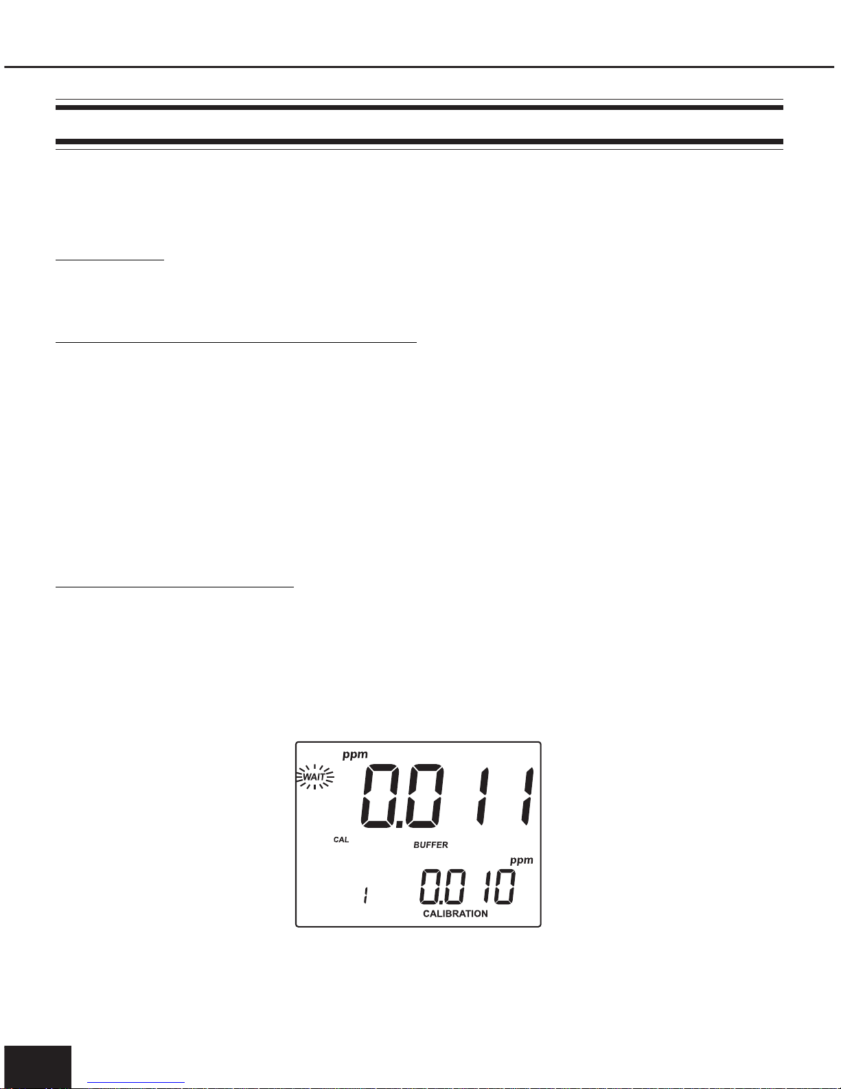
• Press the CAL key. The primary LCD will display the ppm value using the current offset and
slope. The “CAL”, “BUFFER”, “1”, “CALIBRATION” tags will appear and the “0.010”
ppm standard will be displayed on the secondary LCD.
• If necessary, press the UP and DOWN arrow keys to select a different standard value.
• The “WAIT” tag will blink on the LCD until the reading is stable.

www.milwaukeetesters.com
15
• When the reading is stable and close to the selected standard, the “READY” and
“ACCEPT” tags will blink.
• Press the GLP/ACCEPT key to confirm calibration.
• The calibrated value will be displayed on the primary LCD and the second expected
standard value on the secondary LCD.
NoteNote
NoteNote
Note: The instrument will automatically skip the standard used for the first point.
• After the first calibration point is accepted, immerse the ISE electrode approximately 4 cm
(1½”) into the second calibration solution.
• If necessary, press the UP and DOWN arrow keys to select the standard value.
• The “WAIT” tag will blink on the LCD until the reading is stable.
• When the reading is stable and close to the selected standard, the “READY” and “ACCEPT”
tags will blink.
• Press the GLP/ACCEPT key to confirm calibration.
• The instrument stores the calibration value and returns to normal measurement mode.
NotesNotes
NotesNotes
Notes:
•If the mV value is out of the mV range (±2000), the closest full-scale value will be displayed
blinking.

Instruction Manual Mi 160 Bench Meter
1616
1616
16
• If the new slope is out of the slope window, “WRONG BUFFER” and “WRONG
PROBE” messages will blink alternately. In this case, check if the correct standard has
been used or refresh the electrode by following the ceaning procedure. If necessary,
change the standard or the electrode.
The slope window is within ±20 mV and ±105 mV if ion charge is not specified
(UndF option in SETUP menu), or between 50% and 120% of default slope for the
corresponding ion charge.
Default slope values (mV/decade):
– 59.16 (monovalent anion) - ion charge is –1
59.16 (monovalent cation) - ion charge is 1
– 29.58 (divalent anion) - ion charge is –2
29.58 (divalent cation) - ion charge is 2
100 - ion charge is “UndF”
• Press LOG/CLR during calibration if you want to clear calibration data and return to
the default values. The instrument will display “CLr CAL” message and then return to
measurement mode.
• Press the RANGE key to display temperature reading during calibration.
ONE-POINT CALIBRATIONONE-POINT CALIBRATION
ONE-POINT CALIBRATIONONE-POINT CALIBRATION
ONE-POINT CALIBRATION
• Press the CAL key after first calibration point is accepted. The instrument memorizes the onepoint calibration data and returns to measurement mode.
GOOD LABORATORY PRACTICE (GLP)
GLP is a set of functions that allows storage and retrieval of calibration data and electrode status.
All data regarding pH and ISE calibration is stored for the user to review when necessary.
CALIBRATION ALARM TIME-OUTCALIBRATION ALARM TIME-OUT
CALIBRATION ALARM TIME-OUTCALIBRATION ALARM TIME-OUT
CALIBRATION ALARM TIME-OUT
For pH calibration, Mi 160 allows the user to set the number of days (1 to 14) before the next
required calibration. The default setting is OFF (disabled).
The instrument checks the time-out and out the time elapsed, the “CALIBRATION EXPIRED”
message will blink as a reminder.
NoteNote
NoteNote
Note: If the instrument is not calibrated, the “CALIBRATION EXPIRED” message will be
displayed even if the calibration time-out feature is disabled in SETUP menu.

www.milwaukeetesters.com
17
LAST LAST
LAST LAST
LAST
pp
pp
p
H CALIBRATION DATAH CALIBRATION DATA
H CALIBRATION DATAH CALIBRATION DATA
H CALIBRATION DATA
pH calibration data is stored automatically after a successful calibration.
To view the last pH calibration data, press the GLP/ACCEPT key while in pH measurement mode.
The instrument will display the time (hh:mm:ss) of the last calibration.
Press the arrow keys and the instrument will display the next calibration parameter (pressing
the UP key):
• The date (MM.DD.YYYY).
• The pH calibration slope value on the primary LCD and the offset on the secondary LCD.

Instruction Manual Mi 160 Bench Meter
1818
1818
18
• The pH calibration buffers in calibrating order.
The first pH calibration buffer:
• The second pH calibration buffer:
• The third pH calibration buffer:
NotesNotes
NotesNotes
Notes:
• The “OLd” message displayed beneath the pH value means that this buffer was not
used during last calibration. Press SETUP if you want to see calibration date (or time
if old calibration was performed in the same day with current calibration).

www.milwaukeetesters.com
19
• The “no BUFFER” message means that the instrument was calibrated in less than three points.
• The meter displays “OFF” if the function is disabled,
or the number of days before the calibration alarm will be displayed (e.g. 5 days), or from
the time calibration expired (e.g. –3 days).
• Instrument Identification Code. When using several identical meters it may be useful to
uniquely identify them by assigning an ID code to each meter.
LAST LAST
LAST LAST
LAST
ISEISE
ISEISE
ISE
CALIBRATION DATA CALIBRATION DATA
CALIBRATION DATA CALIBRATION DATA
CALIBRATION DATA
ISE calibration data is stored automatically after a successful calibration.
To view last ISE calibration data, press the GLP/ACCEPT key while in ISE measurement mode.
The instrument will display the time (hh:mm:ss) of the last calibration as in pH GLP mode.
Press the arrow UP key and the instrument will display the following calibration parameters:
Instruction Manual Mi 160 Bench Meter
2020
2020
20
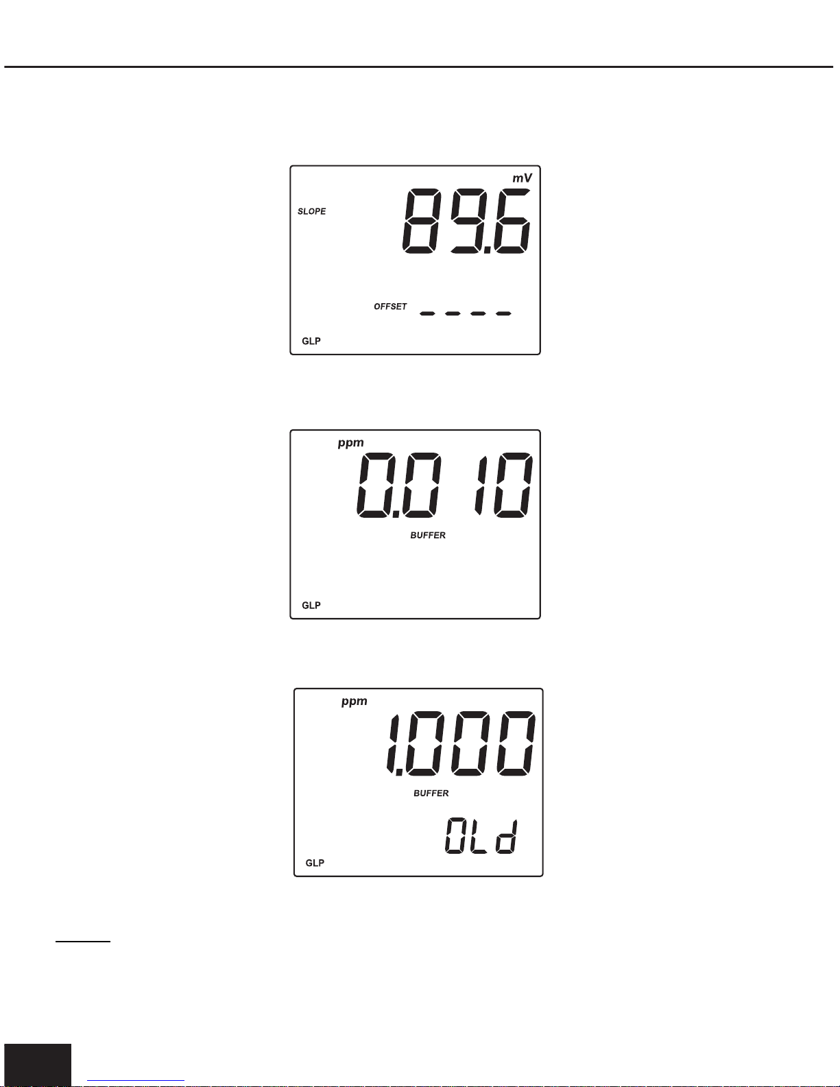
• The date (MM.DD.YYYY) as in pH GLP mode.
• The value slope on the primary LCD and the offset on the secondary LCD.
• The first calibration standard.
• The second calibration standard.
• The instrument ID as in pH GLP mode.
NotesNotes
NotesNotes
Notes:
•The “OLd” message displayed beneath the ppm value means that this standard was not
used during last calibration. Press SETUP if you want to see calibration date (or time if old
calibration was performed in the same day with current calibration).

www.milwaukeetesters.com
21
• If “no BUFFER” message appears on the LCD, the instrument informs you that
calibration was performed in only one point.
• If a one-point calibration is performed after a two-point calibration, the instrument
will keep the old slope.
• Press the GLP/ACCEPT key at any moment and the instrument will return to measurement mode.
• If calibration has not been performed for the selected range, the instrument displays
“no CAL” message blinking.
LOGGING
Up to 50 readings can be stored into memory for each measurement range (pH, mV/Rel mv
and ISE).
LOGGING THE CURRENT DATALOGGING THE CURRENT DATA
LOGGING THE CURRENT DATALOGGING THE CURRENT DATA
LOGGING THE CURRENT DATA
To store the current reading into memory press the LOG/CLR key while in measurement
mode.
The instrument will display the current date (MM.DD) on the primary LCD and the record
number on the secondary LCD, along with “LOG” tag (see example below: record No. 12,
dated May 18).

Instruction Manual Mi 160 Bench Meter
2222
2222
22
The instrument then displays the amount of free log space for about one second and returns
to normal measurement mode (e.g. 45 records free).
If there are less than 6 memory locations remaining, the record number and “Lo” message will
blink to alert the user.
If the log space is full, “FULL LOC” message will be displayed and no more data will be saved.
If the LOG/CLR key is pressed while in measurement mode, a complete set of information is
stored.
VIEW LOGGED DATAVIEW LOGGED DATA
VIEW LOGGED DATAVIEW LOGGED DATA
VIEW LOGGED DATA
Press the MR key to retrieve the information stored while in measurement mode.
If no data is logged, the instrument displays “no rEC” message for the selected range.

www.milwaukeetesters.com
23
Otherwise, the instrument will display the
pHpH
pHpH
pH,
Rel mVRel mV
Rel mVRel mV
Rel mV or
ppmppm
ppmppm
ppm value on the primary LCD and
the last stored record number along with “LOG” tag.
Pressing the arrow keys, the instrument will display the same parameter but for a different record:
Press the RANGE key and the instrument will display the next logged parameter:
• The mV value on the primary LCD and the temperature on the secondary LCD.
or
or

Instruction Manual Mi 160 Bench Meter
2424
2424
24
• The date: month and day on the primary LCD and the year on the secondary LCD, along
with “DATE” tag.
• The time: hour and minutes on the primary LCD and the seconds on the secondary LCD,
along with “TIME” tag.
• The slope on the primary LCD and the offset on the secondary LCD, along with “SLOPE”
and “OFFSET” tags.
NoteNote
NoteNote
Note: If in Rel mV RECALL mode, the instrument will display dashes for slope and if in ISE
RECALL mode, it will display dashes for offset.
• The “dEL” message on the primary LCD and the record number on the secondary LCD,
along with “ACCEPT” tag blinking.

www.milwaukeetesters.com
25
NotesNotes
NotesNotes
Notes:
•If one of the arrow keys is pressed while “dEL” message is displayed, the next/previous
record number will be selected.
•If the SETUP key is pressed, the secondary LCD will toggle between the record number and
“ALL” message.
•Press the GLP/ACCEPT key to delete the selected or all records.
•If “dEL ALL” option was selected, all records for the selected range are deleted and the
instrument returns to measurement mode.
•After deleting a record, the “nuLL” message is displayed on the LCD for the selected record.
Press the MR key to exit the RECALL mode at any time.

Instruction Manual Mi 160 Bench Meter
2626
2626
26
SETUP
Setup mode allows viewing and modifying the following parameters:
• Calibration Alarm Time-Out (pH range only)
• Buffer Display (pH range only)
• Ion Charge (ISE range only)
• Current Time (hh:mm)
• Current Date (MM.DD.YYYY)
• Beep Status
• Baud Rate (serial communication)
• Instrument ID
• Temperature Unit
To enter SETUP mode, press and hold the SETUP key for about 3 seconds while in normal
measurement mode.
Select the desired setup parameter using the UP and DOWN arrow keys.
Press the CAL key if you want to change the item value. The selected item (e.g. hour) will start
blinking.
Press the arrow
keys to change the blinking value.
If there is another item to be set (e.g. minutes), press the RANGE key, and that item will start
blinking.

www.milwaukeetesters.com
27
Press the arrow
keys to change the blinking value.
Press the GLP/ACCEPT key to accept the value or the CAL key to escape.
Press the arrow
keys to select the next/previous parameter.
Press the SETUP key to exit SETUP menu at any time.
The following table lists the SETUP parameters, their valid values range and the factory settings
(default):
NotesNotes
NotesNotes
Notes:
•If “dISP” option is ON, the tags corresponding to the calibrated buffers are displayed on the
LCD while in pH measurement mode.
•To select the right ion charge, different ion types and their charge are listed in the table
below:
In Id Instrument ID 0000 to 9999 0000
bEEP Beep Status ON/OFF OFF
OFF dAY Alarm Time Out OFF or 1 to 14 days OFF
TIME Time (hh:mm) 00:00 to 23:59 00:00
Item Description Valid values Default
dISP Display Cal Buffers ON/OFF ON
IonCG Ion Charge UndF or -2; -1; 1; 2 UndF
tEMP Temperature Unit °C or °F °C
DATE Date (MM.DD.YYYY) 01.01.2000-12.31.2099 01.01.2005
bAud Baud Rate 600;1200;2400;4800;9600 2400
ION CHARGE ION types
-2 (divalent anions) S, CO
3
-1 (monovalent anoins) F, Cl, Br, I, CN, SCN, ClO4, NO
3
1 (monovalent cations) H, Na, K, Ag, NH
4
2 (divalent cations) Mg, Ca, Ba, Cd, Cu, Pb
UndF Undefined ion

Instruction Manual Mi 160 Bench Meter
2828
2828
28
mV CALIBRATION (for technical personnel only)
The
Mi 160Mi 160
Mi 160Mi 160
Mi 160 is factory calibrated for mV.
Martini’s ORP electrodes are interchangeable and no mV calibration is needed when they are
replaced.
If the mV measurements are inaccurate, mV recalibration should be performed.
For an accurate recalibration, contact your dealer or the nearest Martini Customer Service
Center, or follow the instructions below.
A two or three-point calibration can be performed at 0.0 mV, 600.0 mV and 1800.0 mV.
• Attach to the BNC connector a mV simulator with an accuracy of ±0.1 mV.
• With the instrument off, press and hold the CAL & GLP/ACCEPT keys, then power on the
instrument. The “CALIBRATION” tag will appear, and the secondary LCD will show 0.0 mV.
• Set 0.0 mV on the simulator.
• When the reading is stable and close to the selected calibration point, the “READY” and
“ACCEPT” tags will blink.
• Press the GLP/ACCEPT key to accept the calibration point. The secondary LCD will display
600 mV.
• Set 600.0 mV on the simulator.
• When the reading is stable and close to the selected calibration point, the “READY” and
“ACCEPT” tags will blink.
• Press the GLP/ACCEPT key to accept the calibration point. The secondary LCD will display
1800 mV.
• Set 1800.0 mV on the simulator.
• When the reading is stable and close to the selected calibration point, the “READY” and
“ACCEPT” tags will blink.
• Press the GLP/ACCEPT key to accept the calibration point. The instrument returns to
measurement mode.
NotesNotes
NotesNotes
Notes:
•If the reading is not close to the selected calibration point, “WRONG” tag will blink. Verify
calibration condition or contact your vendor if you cannot calibrate.
•To exit the calibration mode press the CAL key in any moment and the instrument will return to
measurement mode. If you exit calibration after 600 mV is confirmed, the 600 mV range is
calibrated and calibration parameters are memorized.

www.milwaukeetesters.com
29
TEMPERATURE CALIBRATION (for technical personnel only)
The
Mi 160Mi 160
Mi 160Mi 160
Mi 160 is factory calibrated for temperature.
Martini’s temperature probes are interchangeable and no temperature calibration is needed
when they are replaced.
If the temperature measurements are inaccurate, temperature recalibration should be performed.
For an accurate recalibration, contact your dealer or the nearest Martini Customer Service
Center, or follow the instructions bellow.
• Prepare a vessel containing ice and water and another one containing hot water
(at 50 °C). Place insulation material around the vessels to minimize temperature changes.
• Use a calibrated thermometer with a resolution of 0.1°C
• With the instrument off, press and hold the MR & LOG/CLR keys, then power on the
instrument. The “CALIBRATION” tag will appear and the secondary LCD will show 0.0 °C.
• Immerse the temperature probe in the vessel with ice and water as near as possible to the
reference thermometer. Allow a few seconds for the probe to stabilize.
• Use the UP and DOWN arrow keys to set the reading on the secondary LCD to the one
measured by the reference thermometer. When the reading is stable and close to the
selected calibration point, the “READY” and “ACCEPT” tags will blink.
• Press the GLP/ACCEPT key to accept the calibration point. The secondary LCD will show
50.0 °C.
• Immerse the temperature probe in the second vessel as near as possible to the reference
thermometer. Allow a few seconds for the probe to stabilize.
• Use the UP and DOWN arrow keys to set the reading on the secondary LCD to that of the
hot water.
• When the reading is stable and close to the selected calibration point, the “READY” and
“ACCEPT” tags will blink.
• Press the GLP/ACCEPT key to accept the calibration point. The instrument returns to
measurement mode.
NoteNote
NoteNote
Note: If the reading is not close to the selected calibration point, “WRONG” tag will blink.
Change the temperature probe and restart calibration.

Instruction Manual Mi 160 Bench Meter
3030
3030
30
PC INTERFACE
Data transmission from the instrument to the PC can be done with the
Mi 5200Mi 5200
Mi 5200Mi 5200
Mi 5200 Windows
®
compatible software, when using the RS232 or USB serial interface.
Mi 5200Mi 5200
Mi 5200Mi 5200
Mi 5200 also offers
graphing and on-line help feature.
Data can be exported to the most popular spreadsheet programs for further analysis.
To connect the instrument to a PC through the RS232 port, use the Martini
MA 9350MA 9350
MA 9350MA 9350
MA 9350 cable
connector.
To connect the instrument to a PC through the USB port, use a standard USB cable.
Make sure that your instrument is switched off and plug one connector of the cable to the
instrument RS232/USB connector and the other to the serial port of your PC.
NotesNotes
NotesNotes
Notes:
•Other cables than
MAMA
MAMA
MA
93509350
93509350
9350 may use a different configuration. In this case, communication
between instrument and PC may not be possible.
•Keep only one cable connected (RS232 or USB) during PC communication to avoid
possible errors.
•If you are not using Martini Instruments
Mi 5200Mi 5200
Mi 5200Mi 5200
Mi 5200 software, please see the following
instructions.
SENDING COMMANDS FROM PCSENDING COMMANDS FROM PC
SENDING COMMANDS FROM PCSENDING COMMANDS FROM PC
SENDING COMMANDS FROM PC
It is also possible to remotely control the instrument with any terminal program. Use
MA 9350MA 9350
MA 9350MA 9350
MA 9350
cable to connect the instrument to a PC, start the terminal program and set the communication options as follows: 8, N, 1, no flow control.
COMMAND TYPESCOMMAND TYPES
COMMAND TYPESCOMMAND TYPES
COMMAND TYPES
To send a command to the instrument follow the next scheme:
<*> <command> <CR>
where: <*> is the command prefix.
<command> is the command code.
NoteNote
NoteNote
Note: Either small or capital letters can be used.
UNIT CHANGE COMMANDUNIT CHANGE COMMAND
UNIT CHANGE COMMANDUNIT CHANGE COMMAND
UNIT CHANGE COMMAND
CHU xxCHU xx
CHU xxCHU xx
CHU xx Change the instrument unit according with the parameter value (xx):
• xx=01 pH range/0.01 resolution
• xx=03 mV / Rel mV range
• xx=05 ppm range

www.milwaukeetesters.com
31
The instrument will answer for this command with:
<STX> <answer> <ETX>
where: <STX> is 02 ASCII code character (start of text)
<ETX> is 03 ASCII code character (end of text)
<answer>:
<ACK> is sent for a recognized command
<CAN> is sent when the instrument is logging
<Err6>/<Err8> is sent when the command is incorrect or the instrument is not in
measurement mode.
COMMANDS REQUIRING AN ANSWERCOMMANDS REQUIRING AN ANSWER
COMMANDS REQUIRING AN ANSWERCOMMANDS REQUIRING AN ANSWER
COMMANDS REQUIRING AN ANSWER
The instrument will answer for these commands with:
<STX> <answer> <checksum> <ETX>
where the checksum is the bytes sum of the answer string sent as 2 ASCII characters.
All the answer messages are with ASCII characters.
RPHRPH
RPHRPH
RPH Causes the instrument to send a complete set of readings in according with the pH
range.
RMVRMV
RMVRMV
RMV Causes the instrument to send a complete set of readings in according with the mV
/ Rel mV range.
RISRIS
RISRIS
RIS Causes the instrument to send a complete set of readings in according with the ISE
range.
MDLMDL
MDLMDL
MDL Requests the instrument model name and firmware code (16 ASCII chars).
INFINF
INFINF
INF Requests the calibration data and the setup parameters.
SAMSAM
SAMSAM
SAM Requests the number of logged samples (12 chars).
LDPHLDPH
LDPHLDPH
LDPH Requests the xxx
th
pH record logged data.
LDMVLDMV
LDMVLDMV
LDMV Requests the xxx
th
mV/Rel mV record logged data.
LDISLDIS
LDISLDIS
LDIS Requests the xxxth ISE record logged data.
LAPHLAPH
LAPHLAPH
LAPH Requests all pH Log on demand.
LAMVLAMV
LAMVLAMV
LAMV Requests all mV/Rel mV Log on demand.
LAISLAIS
LAISLAIS
LAIS Requests all ISE Log on demand.
NotesNotes
NotesNotes
Notes:
•“Err8” is sent if the instrument is not in measurement mode.
•“Err6” is sent if the requested range is not available.
•“Err4” is sent if the requested set parameter is not available.
•“Err3” is sent if the Log on demand is empty.
•Invalid commands will be ignored.

Instruction Manual Mi 160 Bench Meter
3232
3232
32
ELECTRODE CONDITIONING & MAINTENANCE
PREPARATION PROCEDUREPREPARATION PROCEDURE
PREPARATION PROCEDUREPREPARATION PROCEDURE
PREPARATION PROCEDURE
Remove the electrode protective cap.
DO NOT BE ALARMED IF ANY SALT DEPOSITS ARE PRESENT. This is normal with
electrodes and they will disappear when rinsed with water.
During transport tiny bubbles of air may have formed inside the glass bulb. The electrode
cannot function properly under these conditions. These bubbles can be removed by
“shaking down” the electrode as you would do with a glass thermometer.
If the bulb and/or junction are dry, soak the electrode in
MA 9015MA 9015
MA 9015MA 9015
MA 9015 storage solution for
at least one hour.
For refillable electrodes, if the refill solution (electrolyte) is more than 2½ cm (1”) below
the fill hole, add the appropriate electrolyte solution.
MEASUREMENTMEASUREMENT
MEASUREMENTMEASUREMENT
MEASUREMENT
Rinse the electrode tip with distilled water, immerse it (4 cm / 1½") into the sample and
stir gently for a few seconds.
For a faster response and to avoid cross contamination of the samples, rinse the
electrode tip with the solution to be tested before taking any measurements.
STORAGE PROCEDURESTORAGE PROCEDURE
STORAGE PROCEDURESTORAGE PROCEDURE
STORAGE PROCEDURE
To minimize clogging and ensure a quick response time, the glass bulb and the junction
should always be kept moist.
When not in use, store it with a few drops of
MM
MM
M
AA
AA
A
90159015
90159015
9015 storage solution in the protective cap.
NEVER STORE THE ELECTRODE IN DISTILLED OR DEIONIZED WATER.
PERIODIC MAINTENANCEPERIODIC MAINTENANCE
PERIODIC MAINTENANCEPERIODIC MAINTENANCE
PERIODIC MAINTENANCE
Inspect electrode and cable. The cable used for the connection to the instrument must
be intact and there must be no points of broken insulation on the cable or cracks on the
electrode stem or bulb. If any scratches or cracks are present, replace the electrode.
Rinse off any salt deposits with water.
Connectors must be perfectly clean and dry.
For refillable electrodes:
Refill the electrode with fresh electrolyte (see the electrode’s specifications to select the
correct refilling solution). Allow the electrode to stand upright for 1 hour. Follow the
Storage Procedure above.

www.milwaukeetesters.com
33
CLEANING PROCEDURECLEANING PROCEDURE
CLEANING PROCEDURECLEANING PROCEDURE
CLEANING PROCEDURE
• General Soak in
MAMA
MAMA
MA
90169016
90169016
9016 General Cleaning Solution for approx. ½ hour.
IMPORTANT: After performing any of the cleaning procedures, rinse the electrode thoroughly
with distilled water and soak it in
MM
MM
M
AA
AA
A
90159015
90159015
9015 storage solution for at least 1 hour before taking
measurements.
TROUBLESHOOTING
SMOTPMYSMELBORPNOITULOS
.tfirdevissecxe/esnoperwolS.edortceleHpytriD
nipitedortceleehtkaoS
dnasetunim03rof6109AM
gninaelCehtwollo
fneht
.erudecorP
dnapusetautculfgnidaeR
.)esion(nwod
.noitcnuJytrid/deggolC
elballifer(leveletylortcelewoL
.)ylnosedortcele
htiwllifeR.edortceleehtnaelC
2109AMetylortcelehserf
.)ylnosedortceleelballifer(
llufgnik
nilbswohsyalpsiD
eulavelacs
.egnarfotuognidaeR
nihtiwsielpmasehtkcehC
;egnarelbarusaem
dnaleveletylortcele
kcehC
.sutatsedortcelelareneg
.egnarfotuoelacsVm.noitcnujyrdroenarbmemyrD
niedortceleehtkaoS
rofnoitulosegarots5109AM
.setunim03tsaelta
ro"°C"gniknilbswohsyalpsiD
."°F"
erutarepmetredrofotuO
.eborp
erutarepmetehte
calpeR
.eborp
htiwkrowtonseodreteM
.eborperutarepmet
.eborperutarepmetnekorB
erutarepmetehtecalpeR
.eborp
ro
etarbilacotsliafreteM
.sgnidaerytluafsevig
.edortceleHpnekorBedortceleehtecalpeR
syalpsidretemehtputratst
A
yltnenamrepsgatDCLlla
.dekcolbsisyekehtfoenO
rodraobyekehtkcehC
relaedruoytcatnoc
taegassem"2rE,1rE,0rE"
.putrats
lanretnI.rorre
ynarorelaedruoytcatnoC
ecivreSstnemurtsnIinitraM
.retneC

Instruction Manual Mi 160 Bench Meter
3434
3434
34
ACCESSORIES
MA 9001MA 9001
MA 9001MA 9001
MA 9001 pH 1.68 Buffer Solution (230 mL bottle)
MA 9004MA 9004
MA 9004MA 9004
MA 9004 pH 4.01 Buffer Solution (230 mL bottle)
MA 9006MA 9006
MA 9006MA 9006
MA 9006 pH 6.86 Buffer Solution (230 mL bottle)
MA 9007MA 9007
MA 9007MA 9007
MA 9007 pH 7.01 Buffer Solution (230 mL bottle)
MA 9009MA 9009
MA 9009MA 9009
MA 9009 pH 9.18 Buffer Solution (230 mL bottle)
MA 9010MA 9010
MA 9010MA 9010
MA 9010 pH 10.01 Buffer Solution (230 mL bottle)
MA 9012MA 9012
MA 9012MA 9012
MA 9012 Refilling Solution for pH electrode (230 mL bottle)
MA 9015MA 9015
MA 9015MA 9015
MA 9015 Storage Solution (230 mL bottle)
MA 9016MA 9016
MA 9016MA 9016
MA 9016 Electrode Cleaning Solution (230 mL bottle)
MA 9112MA 9112
MA 9112MA 9112
MA 9112 pH 12.45 Buffer Solution (230 mL bottle)
MA 9310MA 9310
MA 9310MA 9310
MA 9310 12 VDC Adapter, 220 V
MA 9311MA 9311
MA 9311MA 9311
MA 9311 12 VDC Adapter, 110 V
MA 9315MA 9315
MA 9315MA 9315
MA 9315 Electrode Holder
MA 917B/1MA 917B/1
MA 917B/1MA 917B/1
MA 917B/1 pH Electrode, glass body, refillable
MA 922B/1MA 922B/1
MA 922B/1MA 922B/1
MA 922B/1 ORP Electrode, glass body, refillable
MA 831RMA 831R
MA 831RMA 831R
MA 831R Temperature Probe
MA 9350MA 9350
MA 9350MA 9350
MA 9350 RS232 connection cable (2 meters)

www.milwaukeetesters.com
35
WARRANTYWARRANTY
WARRANTYWARRANTY
WARRANTY
This instrument is warranted against defects in materials and manufacturing for a period of
3 years from the date of purchase. Electrodes and Probes are warranted for 6 months.
If during this period the repair or replacement of parts is required, where the
damage is not due to negligence or erroneous operation by the user, please return
the intrument, electrode and probe to either distributor or our office and the repair
will be effected free of charge.
Damage due to accidents, misuse, tampering or lack of prescribed maintenance is
not covered by the warranty.
Milwaukee/Martini instruments reserves the right to make improvements inMilwaukee/Martini instruments reserves the right to make improvements in
Milwaukee/Martini instruments reserves the right to make improvements inMilwaukee/Martini instruments reserves the right to make improvements in
Milwaukee/Martini instruments reserves the right to make improvements in
design, construction and appearance of its products without advance notice.design, construction and appearance of its products without advance notice.
design, construction and appearance of its products without advance notice.design, construction and appearance of its products without advance notice.
design, construction and appearance of its products without advance notice.
For your Safety don’t use or store the instrument in hazardous environments. To avoid
damages or burns, do not perform any measurement in microwave ovens.

Instruction Manual Mi 160 Bench Meter
3636
3636
36
Sales and Technical Service Contacts:
Milwaukee s.r.l.
C.so Leonardo da Vinci 48/50
21013 Gallarate (VA) ITALY
Tel: +39 0331 26 80 09
Fax: +39 0331 26 80 33
e-mail: sales@milwaukee.191.it
Milwaukee Instruments, Inc.
2950 Business Park Drive
Rocky Mount - NC 27804 - U.S.A.
Tel: +1 252 443 3630
Fax: +1 252 443 1937
e-mail: milwaukee@vol.com
MANMI160 06/08
THANK YOU FOR CHOOSING
www.milwaukeetesters.com
 Loading...