

Martin Fireplaces MD36I DELUXE Maintanance Manual
MD36I DELUXE
RADIANT WOOD BURNING FIREPLACE
INSTALLATION, OPERATION AND MAINTENANCE MANUAL
The MD36I fireplace is an insulated radiant wood burning fireplace with a 36-inch wide front
opening. It comes complete with an interior damper to prevent heat loss when not in use,
and it has fire screens for safe use. The MD36I fireplace may be installed in residential and
manufactured type homes as explained by this instruction manual. The MD36I installs with
S-series chimney system components and is designed to utilize the MGD36-series of glass
doors. The MD36I can be converted to a louvered circulating unit by utilizing the MLK36
louver kit, and can utilize the FA2 fan once the fireplace has been converted to a louvered
circulating unit. Natural gas or LP gas log sets may be installed in the MD36I fireplace if
desired, as allowed by local code authorities.
53D9023

CONGRATULATIONS!
You have chosen a fine woodburning fireplace. Your fireplace has been designed and built for years
of heating and viewing enjoyment. Please take time to read this entire manual before installing or
operating your fireplace.
TABLE OF CONTENTS
LISTING AND CODE APPROVALS ............................................................................................................... 2
CAUTIONARY INFORMATION ...................................................................................................................... 3
OPERATION GUIDELINES .......................................................................................................................... 4
CLEARANCES ........................................................................................................................................ 5
FIREPLACE LOCATION ............................................................................................................................. 7
INSTALLATION PREPARATION ................................................................................................................... 8
FLOOR PROTECTION ............................................................................................................................. 10
FIREPLACE COMPONENTS ...................................................................................................................... 12
FIREPLACE INSTALLATION ...................................................................................................................... 14
CHIMNEY INSTALLATION ......................................................................................................................... 15
CHIMNEY OFFSET INSTALLATION ............................................................................................................. 17
CHIMNEY OFFSET AND CAP INSTALLATION ............................................................................................... 18
CHIMNEY CAP INSTALLATION .................................................................................................................. 19
CHIMNEY HEIGHT AND OFFSET CHARTS .................................................................................................. 20
CHIMNEY CAP CHASE INSTALLATION ....................................................................................................... 21
OUTSIDE COMBUSTION AIR PRECAUTIONS & RECOMMENDATIONS ................................................................ 22
COMBUSTION AIR ASSEMBLY ................................................................................................................. 24
GAS APPLIANCE INSTALLATION .............................................................................................................. 24
TRIM INSTALLATION .............................................................................................................................. 26
GLASS DOOR INSTALLATION AND FAN ACCESSORY ................................................................................... 28
FIREPLACE OPERATION ......................................................................................................................... 29
MAINTENANCE AND SAFETY .................................................................................................................. 31
PARTS DIAGRAM AND LIST .................................................................................................................... 34
LIMITED WARRANTY ............................................................................................................................ 36
LISTING AND CODE APPROVALS
The instructions contained in this manual provide the information necessary to install this fireplace in accordance with
Underwriter’s Laboratories requirements and in compliance with the National Fire Protection Association Standard No.
211. Some codes may require the fireplace and chimney be electrically grounded. Before beginning the installation, you
should check with local building officials to obtain required permits and assure compliance with local regulations and
coded. If you encounter problems with code requirements, contact your dealer for assistance.
This fireplace is listed by OMNI-Test Laboratories, Inc. to U.L. 127-standard for factory-built fireplaces. The design of this
fireplace and these instructions complied with applicable safety standard for a factory built fireplace in effect at the time
the fireplace was manufactured. You should be aware, however, that failure to install, operate, and maintain this or any
other factory built fireplace properly can result in a house fire or other occurences that could cause deaths, injuries, and
property damages. It is very important that the persons installing and/or supervising the installation of this fireplace have
appropriate skills in using the tools and techniques required: and reading and comprehension skills sufficient to read
and follow these instructions. These instructions contain warnings, cautions, and notes to emphasize important safety
information. To assure that safe and satisfactory service is received from this fireplace, please read the following special
notices and all the contents of this manual.
2
53D9023

CAUTIONARY INFORMATION
1. Read these instructions entirely before beginning any part of the installation. Save these instructions for
any future repairs.
2. Use these instructions as a guide during the installation of the fireplace.
3. Be sure these instructions become the property of and are reviewed by all future users of this fireplace to
encourage proper operation and maintenance.
4. All the parts used with this fireplace system must be installed in accordance with these installation
instructions. Failure to do so may be hazardous and will void the warranty.
5. This fireplace and accessories should not be altered in any way that is not specifically recommended in
this manual.
6. Refer to your local building code for local requirements pertaining to installation of factory-built fireplaces.
Martin Hearth & Heating fireplaces are intended for installation and use according to standard NFPA 211
of the National Fire Protection Association.
7. This fireplace must not be installed with a masonry flue.
2
8. This fireplace and chimney should not be used for venting a wood or coal burning heater or fireplace insert.
WARNING: DO NOT INSTALL A SEPARATE SOLID FUEL INSERT OR GAS FIREPLACE INSERT IN THIS FIREPLACE AND CHIMNEY
SYSTEM WITHOUT WRITTEN AUTHORIZATION FROM MARTIN HEARTH & HEATING.
9. Do not pack required air spaces with combustible material or insulation not specifically recommended for
use in such areas.
INTENDED PRODUCT USAGE
This fireplace is intended for supplemental heating only and is not intended for use as a primary heating
system.
This fireplace is designed to sit directly on a combustible floor. The fireplace must be installed with clearances
to combustible building materials as specified by this manual. Only parts manufactured by Martin Hearth &
Heating and labeled for use with this fireplace should be used in the installation of the fireplace except for special
roof flashings that may be fabricated locally. The use of improper parts in the installation can be hazardous
and voids the warranty offered by Martin Hearth & Heating.
This fireplace is designed to burn solid wood fuel (wood), UL- classified processed solid fuel fire logs, or a certified
decorative gas appliance may be installed in the fireplace as described later by this instruction manual.
This fireplace is not designed to burn coal, unplumbed liquid fuels, unplumbed gaseous fuels or household
refuse. Any attempt to burn these fuels in the fireplace can be hazardous.
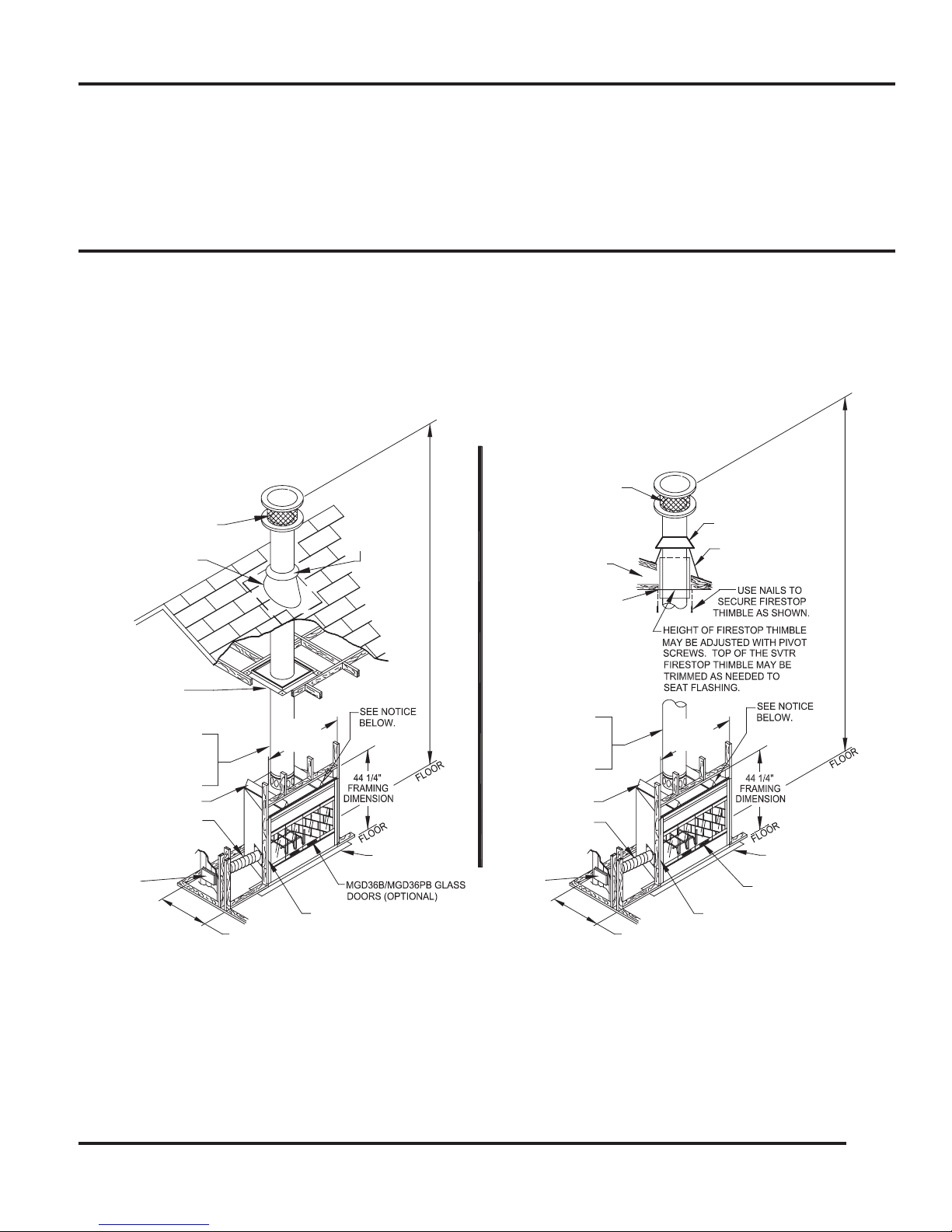
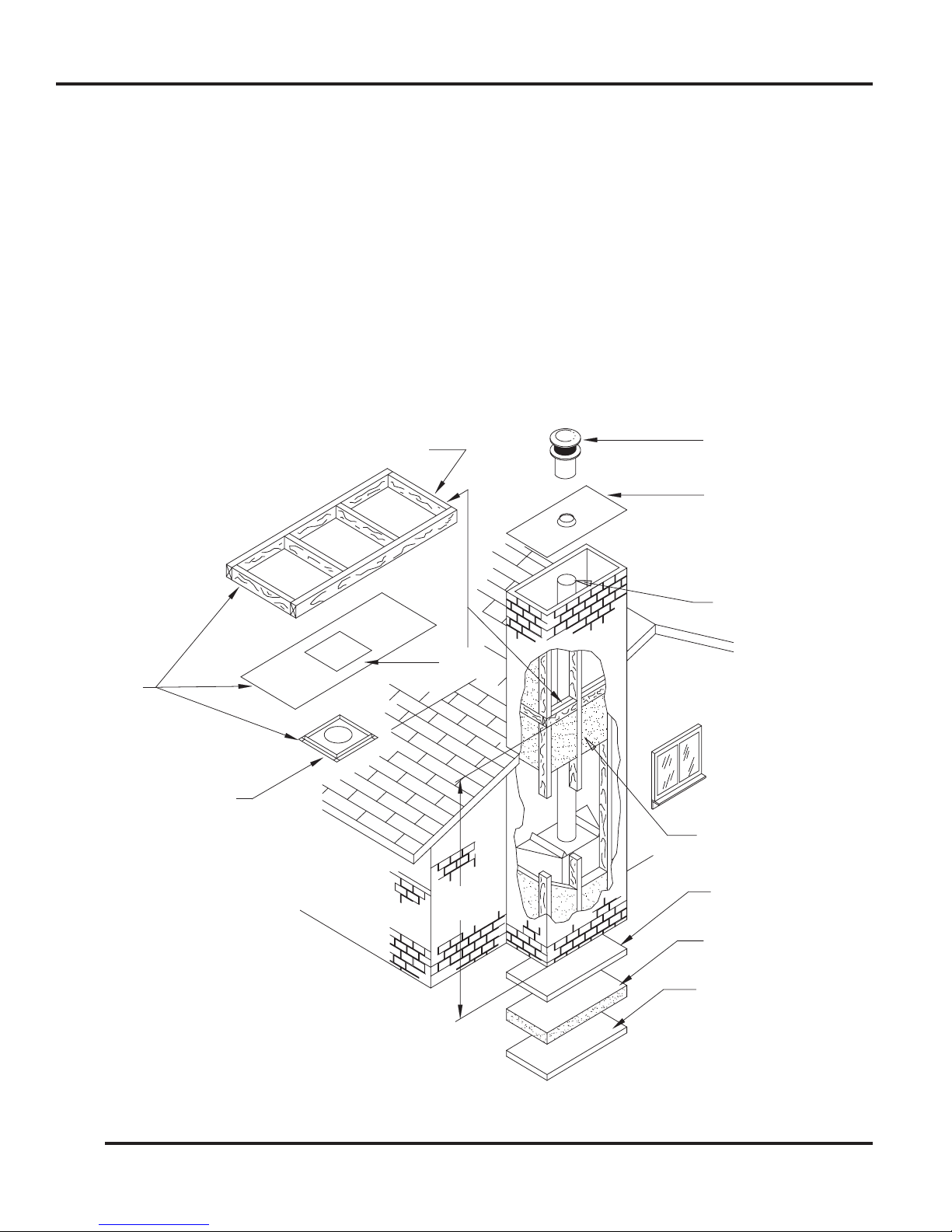
NOTICE:
FIREPLACE MAY BE INSTALLED IN MANUFACTURED HOMES WHICH HAVE A VENTED ATTIC SPACE IF THE FIREPLACE IS EQUIPPED WITH
MGD36B OR MGD36PB GLASS DOORS, AN AK6 OUTSIDE COMBUSTION AIR KIT (INSTEAD OF THE AK4 OUTSIDE COMBUSTION
AIR KIT OFFERED FOR RESIDENTIAL TYPE HOMES AS DESCRIBED LATER BY THIS INSTRUCTION MANUAL), A SVTR FIRESTOP THIMBLE,
AND THE MINIMUM INSTALLED HEIGHT FROM FLOOR TO FLUE OUTLET IS 16 FEET. SEE FIGURE 1.
THIS FIREPLACE IS NOT DESIGNED FOR INSTALLATION IN MANUFACTURED HOMES WITHOUT A VENTED ATTIC SPACE. THE
CAUTION: DO NOT USE A FIREPLACE INSERT OR OTHER PRODUCT NOT SPECIFIED FOR USE WITH THIS FIREPLACE.
WARNING: IMPROPER INSTALLATION OR USE OF THIS FIREPLACE WILL VOID ITS WARRANTY AND CAN CAUSE:
1. Damage to the fireplace from overheating.
2. Hazardous temperatures to develop on combustible materials adjacent to the fireplace or
chimney.
3. The emission of smoke, sparks or hazardous gases into the dwelling.
4. Leakage of rain water into the dwelling.
3
53D9023

OPERATION GUIDELINES
As wood is burned in the fireplace, room air entering the fireplace through vents is circulated around the firebox
of the fireplace. This air circulation protects the firebox from overheating. Fireplace vents must not be blocked or
restricted in any manner. Blocking or restricting air circulation through the fireplace can cause a fire hazard.
In residential type installation, an AK4 outside combustion air kit may be connected to either the left or right side
of the fireplace to allow outside air to enter the firebox through a dampered opening in that side of the fireplace.
This “outside combustion air” feature reduces the room air used for combustion and prevents excessive heat loss
from the room. When the fireplace is in use, the fireplace’s “outside combustion air” damper connected to an AK4
may be opened to allow air from outside to enter the fireplace firebox. When the fireplace is not in use, the “outside
combustion air” damper should be closed to prevent cold air from entering the firebox. An “outside combustion air”
damper is open when its control lever is up, and closed when its control lever is down. A control lever for each
“outside combustion air” damper is located inside the firebox near the top of the side firebrick on each side of the
fireplace. The design of the fireplace allows the routing of the combustion air duct downward or horizontally to
obtain the outside combustion air; this permits flexibility in planning your installation. See Figures 24 thru 27 and
their instructions for typical installation of outside combustion air kits. Review the precautions and recommendations
in this manual pertaining to outside combustion air. Outside air for combustion is optional in residential type
installations unless required by local codes; it is mandatory in manufactured home installations. Use an
AK6 outside combustion air kit in manufactured home installations, instead of the AK4 offered for residential
type installations.
Glass doors (model MGD36B or MGD36PB by Martin Hearth & Heating) may be installed to receive the maximum
benefit from your fireplace. For large fires, the maximum heating benefit from the fireplace will be obtained with thet
doors open due to the high amount of radiant heat being emitted out of the front opening of the fireplace. With a small
fire, or before retiring in the evenings, it is best to operate the fireplace with the doors closed to prevent excessive
room air from being drawn up the chimney. When the doors are open, the mesh screens should be closed to help
keep burning embers from popping out of the firebox.
Glass doors are mandatory on fireplaces installed in manufactured homes.
WARNING: Fireplaces equipped with glass doors should be operated only with the glass doors fully open or fully
closed. If doors are left partly open, gas and flame may be drawn out of the fireplace opening, creating risks of both
fire and smoke.
5
The fireplace also is equipped with a flue damper, which must be open when the fireplace is in use. The flue damper
control lever is located inside the fireplace. The counterweighted damper is operated by simply pushing up to open
or pulling down to close the damper. When the fireplace is not in use, the damper should be closed to prevent cold
air form entering the chimney as well as preventing warm air in the room from escaping up the chimney. NOTE:
It is normal for a small amount of smoke to be released from the upper portion of the fireplace the first few times
you use your new Martin Hearth & Heating fireplace. This results from an oil residue on the metal. Open a door or
window to allow the smoke to escape.
The grate included with this fireplace helps to appropriately locate and contain the burning wood. Failure to use
this grate may cause overheating of parts of the fireplace and allow large pieces of burning wood to roll forward
out of the firebox. If the grate becomes warped or damaged, it must only be replaced by a Martin Hearth & Heating
078355 grate.
All fireplace chimneys are in direct contact with cold air on the exterior of the structure. Consequently, when the
fireplace is not in use, cold air can fall down the chimney of the fireplace to cool off the fireplace chase. Therefore, the
fireplace chase must be insulated to minimize the risk of cold air infiltration to the home. Even if the fireplace chase
is adequately insulated, this cannot completely ensure that cold air infiltration into the structure will be eliminated.
Cold air infiltration is a possibility with any fireplace or device that freely communicates with the air on the outside
of the structure. Today’s homes are more energy-efficient and, therefore, better insulated and tightly constructed.
Unfortunately, when air is removed from the house, as by a bathroom fan, or consumed by a furnace, additional air
is needed to replace the air consumed. Unless the additional air is
4
53D9023.
OPERATION GUIDELINES
612 ROOF
FLASHING
F
L
U
E
O
U
T
LE
T
H
E
IG
H
T
16 FT. = MIN. HEIGHT (2-30∞ ELBOWS)
16 FT. = MIN. HEIGHT (NO OFFSETS)
FP6U AIR DUCT
TOP SPACER
GLASS DOORS
MGD36B/MGD36PB
STORM COLLAR
AK4 OUTSIDE
COMBUSTION
AIR KIT
TO COMBUSTIBLES.)
(1-3/4" MINIMUM AIR SPACE
SF FIRESTOP SPACER
14-1/2" FRAMED OPENING.
REQUIRES A 14-1/2" X
METAL SAFETY
STRI
P
METAL SAFETY
STRI
P
VENTED ATTIC SPACE
MAY USE:
AIR SPACE TO COMBUSTIBLES)
CHIMNEY PIPE (2" MINIMUM
ROUND CHIMNEY
CAP MODEL SC
FLASHING
612 ROOF
(1-3/4" MINIMUM AIR SPACE
SVTR FIRESTOP THIMBLE.
REQUIRES A 14-1/2" X 14-1/2"
TO COMBUSTIBLES.
)
FRAMED OPENING.
(OPTIONAL)
COMBUSTIBLE MATERIALS SHOULD NOT BE INSTALLED BELOW TOP SPACERS OF
THE FIREPLACE. NONCOMBUSTIBLE MATERIALS SUCH AS BRICK OR TILE MAY BE
USED TO TRIM FACE OF THE FIREPLACE BUT SHOULD NOT COVER ANY AIR INLETS.
COMBUSTIBLES MUST NOT OVERLAP BLACK PAINTED SURFACES OF THE FIREPLACE.
NOTICE:
16 FT. = MIN. HEIGHT (NO OFFSETS)
16 FT. = MIN. HEIGHT (2-30∞ ELBOWS
)
21 FT. = MIN. HEIGHT (4-30∞ ELBOWS
)
86 FT. = MAX. HEIGHT (SCS CHIMNEY
SUPPORT EVERY 30 FT.)
FOR AK6 KIT.
FP4U AIR DUCT
FOR AK4 KIT.
S12 (12 IN. LONG) PIPE,
S18 (18 IN. LONG) PIPE,
S36 (36 IN. LONG) PIPE,
S48 (48 IN. LONG) PIPE.
25 3/4"
FRONT TO BACK
FRAMING DIMENSION
NAIL TO FRAMING MEMBER.
CHIMNEY PIPE (2" MINIMUM
AIR SPACE TO COMBUSTIBLES)
MAY USE:
S18 (18 IN. LONG) PIPE,
S36 (36 IN. LONG) PIPE,
S48 (48 IN. LONG) PIPE.
S12 (12 IN. LONG) PIPE,
38 1/2"
FRAMING
DIMENSION
ROUND CHIMNEY
CAP MODEL SC
STORM
COLLAR
F
L
U
E
O
U
T
LE
T
H
E
IG
H
T
RESIDENTIAL HOME
INSTALLATION
TYPICAL FRAMING FOR
TYPICAL FRAMING FOR
MANUFACTURED HOME
INSTALLATION
(TYPICAL FOR RIGHT SIDE.)
NAIL TO FRAMING MEMBER.
(TYPICAL FOR RIGHT SIDE.
)
38 1/2"
DIMENSION
FRAMING
AIR KIT
COMBUSTION
AK6 OUTSIDE
25 3/4"
FRONT TO BACK
FRAMING DIMENSION
TOP SPACER
6
supplied, this can cause a negative pressure in the home. When this happens, the house will draw in outside air
from the cracks in the windows, down the fireplace flue or other locations of air leakage in the home. Because
cold air infiltration may be unavoidable in some structures, Martin Hearth & Heating is not responsible for heat
loss or air infiltration through or around the fireplace.
CLEARANCES
FIGURE 1
5
53D9023
CLEARANCES
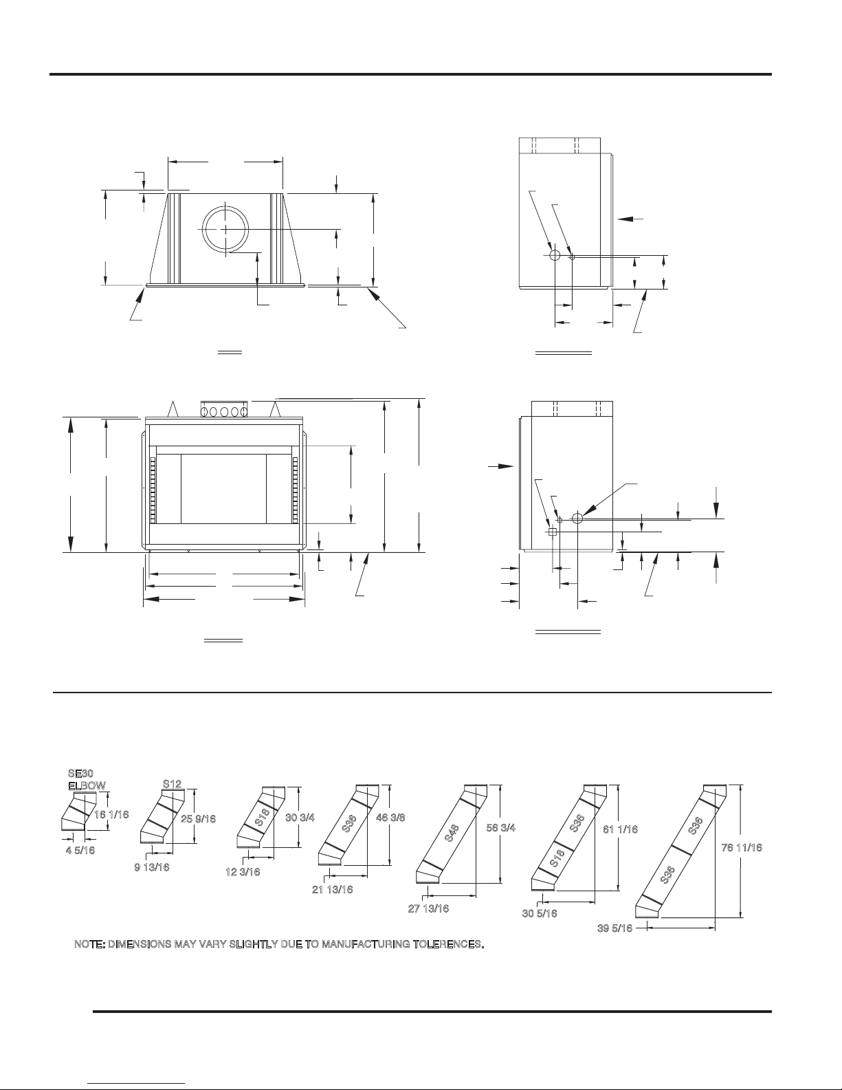
NOTE: DIMENSIONS MAY VARY SLIGHTLY DUE TO MANUFACTURING TOLERENCES.
4 5/16
16 1/16
9 13/16
25 9/16
12 3/16
30 3/4
21 13/16
46 3/8
27 13/16
56 3/4
30 5/16
61 1/16
SE30
ELBOW
S12
S18
S36
S36
S36
S48
S18
S36
39 5/16
76 11/16
3/4
8
21 7/8
NAILING FLANGE
(EACH SIDE)
DIMENSION
FRAMING
25 3/4
FRONT FACE LINE
TOP
10 1/4
(REF)
1/2
25 1/4
9 1/2
23 1/8
1" AIR SPACE
11 1/2
RIGHT SIDE
15 7/8
FRONT
9 1/2
3/4
GAS LINE
JUNCTION BOX
LINE
FLOOR
9 1/4
4 3/4
8 3/4
OUTSIDE AIR
GAS LINE
LEFT SIDE
11 1/2
15 7/8
FLOOR
LINE
9 1/4
8 3/4
FRONT
OUTSIDE AIR
38 1/2
FRAMING
DIMENSION
44 1/4
44
FRAMING DIMENSIONS
36
38
FRONT
38 3/4
38 1/4
LINE
FLOOR
FIGURE 2 (ALL DIMENSIONS IN INCHES.)
FIGURE 3 (ALL DIMENSIONS IN INCHES.)
6
53D9023
FIREPLACE LOCATION
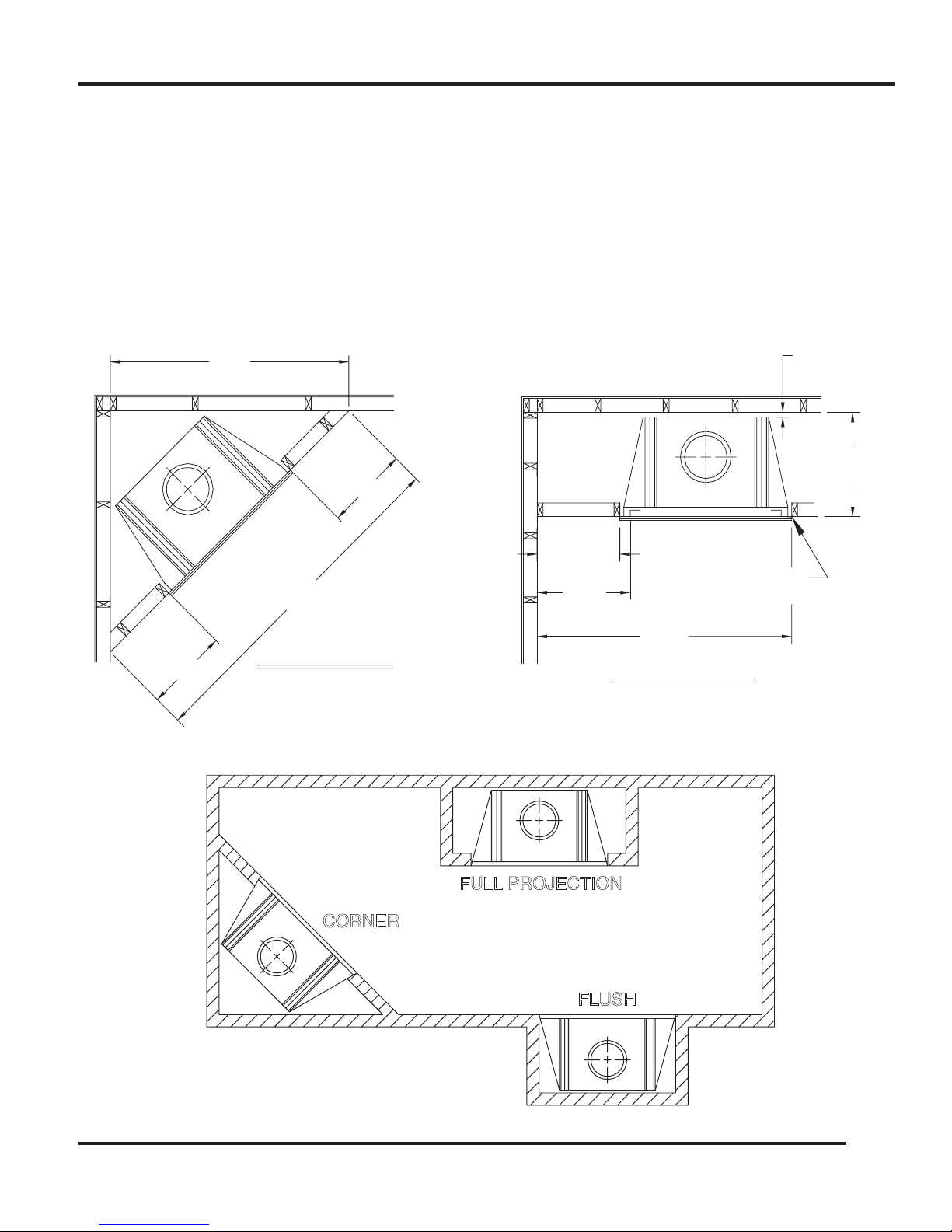
17 5/16
72 5/
8
17 5/16
58 3/
4
22 (MIN
)
20 3/4 (MIN
)
25 3/4 (MIN
)
51 3/
8
1
AIR SPACE
CLEARANCE
INCH
FRAMING
DIMENSION
OPENIN
G
NAIL FLANGE
(EACH SIDE
)
(MIN)
CORNER INSTALLATION
(MIN)
(MIN)
(MIN)
SIDE WALL INSTALLATION
SCREENED
FULL PROJECTION
FLUSH
CORNER
CAUTION: Do not install fireplace over carpeting.
This fireplace does not weigh more than large pieces of furniture and can normally be located near a load
bearing wall without requiring additional foundations or supports. If however, the fireplace is to be trimmed with
a heavy stone or brick facing and hearth extension, be sure the supporting structure is adequate.
Figures 4 and 5 provide dimensional details of the fireplace, required spacing to combustible walls, and some
suggested fireplace locations. When selecting a location, choose one that is away from frequently opened
doors, central heat outlets or returns, or other places where air movements may disturb the airflow around the
fireplace. Air turbulence near the fireplace may cause smoke to spill out of the fireplace opening.
FIGURE 4 (ALL DIMENSIONS IN INCHES.)
FIGURE 5
7
53D9023
INSTALLATION PREPARATION
CONTACTED BY FRAMING MATERIALS .
SCL TELESCOPING
CHIMNEY CAP
FLAT CHASE FLASHING
CHIMNEY SECTIONS
"S" SERIES
INSULATE OUTSIDE
WALLS OF CHASE
SOLID CONTINUOUS
SURFACE
INSULATION
(THERMAL BARRIERS)
OUTSIDE BASE
SF FIRESTOP SPACER
SEE NOTES
JOIST INSULATE SAME AS CEILING
SOLID
SURFACE
R3672 (36" x 72")
OR
R4884 (48" x 84")
8' 0"
LEVEL
NOTES:
1. MODEL SF FIRESTOP
SPACER MUST BE USED.
2. LOCAL CODES MAY NOT REQUIRE
FIRESTOPPING AT THE CEILING LEVEL
FOR CHASE INSTALLATIONS, BUT IT IS
RECOMMENDED FOR SAFETY AND
REDUCING HEAT LOSS.
3. DO NOT INSULATE THE CHASE WITH
BLOWN OR FILL TYPE INSULATION.
INSULATION SHOULD ONLY CONTACT
THE FIREPLACE AT POINTS WHERE
THE FIREPLACE WOULD NORMALLY BE
Survey the planned location for the fireplace for overhead plumbing or electrical wires, etc., that might complicate
the installation or endanger persons installing or cleaning the chimney. Avoid a location where the chimney
cap will be near abrupt changes in the roof shape, nearby wall or embankments, under or near trees or above
the roof of a single story wing of a two story building as shown by Figure 8. All these conditions can cause
turbulence or pressure conditions that can cause poor chimney draft and smoke spillage from the fireplace
opening. Elbows may be used to offset the chimney to avoid obstructions or to locate the chimney cap in a
preferred location. Refer to the sections of this manual pertaining to chimney offsets for instructions on proper
elbow use. Poor installation or location of the chimney cap and/or components can cause wind blown rain to
enter the chimney.
Be sure the selected location will allow a 14-1/2” square combustible material-free space for the chimney to pass
through. If the chimney is to pass through living or storage spaces, be sure there is adequate space to enclose
the chimney to avoid personal contact with, or damage to, the chimney. If the fireplace is to be installed on an
outside wall, the surrounding walls (chase) should be constructed and insulated as shown by Figure 6. Failure
to insulate the fireplace form outside temperatures will cause heat loss through and around the fireplace.
FIGURE 6
8
53D9023
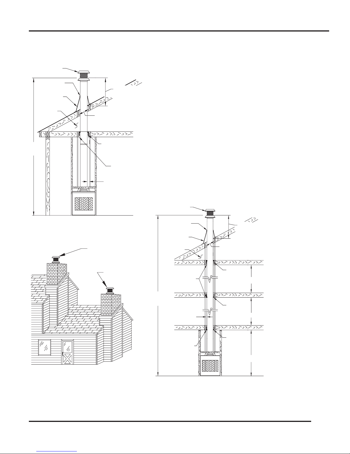
INSTALLATION HEIGHT
STORM COLLAR
(INCLUDED WITH CAP)
(612 OR 1212)
FLASHIN
G
SF FIRESTOP SPACER
(1 3/4" AIR SPACE
CLEARENCE TO
COMBUSTIBLES)
2" MIN. CLEARENCE
TO COMBUSTIBLES
14 1/2" SQUARE
OPENING IN JOIST
FLASHING
(612 OR 1212)
SEE TABLE 1 FOR
ROOF OPENING
SIZE
SC CHIMNEY CAP
SINGLE STORY INSTALLATION WITH ATTIC SPACE
FLUE OUTLET HEIGHT
POOR LOCATION
16 FT.
SEE TABLE
1 FOR ROOF
SF FIRESTO
P
MIN.
SPACER
SF FIRESTOP
SPACER
SF FIRESTO
P
SPACER
OPENING SIZE
SC CHIMNEY CAP
14 1/2" SQUARE HOLE
IN JOIST (1 3/4" AIR
SPACE CLEARANCE
TO COMBUSTIBLES)
86 FT. MAX.
14 1/2" SQUARE HOLE
IN JOIST (1 3/4" AIR
SPACE CLEARANC
E
TO COMBUSTIBLES)
MULTIPLE STORY INSTALLATION
ATTIC SPACE
ATTIC SPACE
3 FT. MIN. HEIGHT,
AND 2 FT. MIN. ABOVE
ANY POINT WITHIN 10
FEET OF CHIMNEY.
2" MIN. CLEARANC
E
TO COMBUSTIBLES
(TYPICAL ALL AROUND.
)
3 FT. MIN. HEIGHT,
AND 2 FT. MIN. ABOVE
ANY POINT WITHIN 10
FEET OF CHIMNEY.
STORM COLLAR
(INCLUDED WITH CAP)
: SCS CHIMNEY SUPPORT REQUIRED EVERY 30 FEET OF INSTALLATION HEIGHT.
*
*
PREFERRED LOCATION
FIRST FLOOR AREA
FLUE OUTLET HEIGHT
SECOND FLOOR AREA
THIRD FLOOR AREA
INSTALLATION PREPARATION
F
IGURE 7
NOTICE:
Chimney must be correct height above the roof
or other obstruction for safety and for proper
draft operation. The chimney must be at least
3 feet higher than the highest point where it
passes through the roof and at least 2 feet higher
than the highest part of the roof or structure
that is within 10 feet of the chimney, measured
horizontally. See Figures 7, 9, and 14.
F
IGURE 9
FIGURE 8
9
53D9023
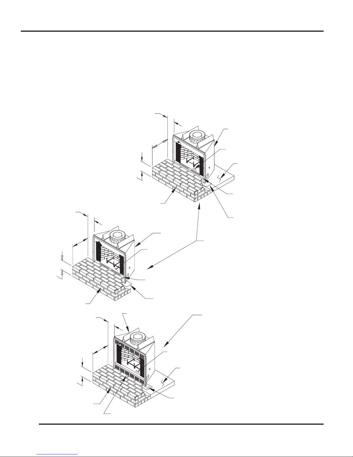
8"
MIN.
16"
8"
MIN.
16"
MIN.
8"
MIN.
16"
MIN.
HEARTH
FIREPLACE
BRICK OR STONE
HEARTH EXTENSION
(52" LONG MIN.)
6"
MIN.
FIREPLACE
HEARTH
MIN.
DO NOT PLACE HEARTH
MATERIALS ABOVE OPENING
OF FIREPLACE.
METAL SAFETY STRI
P
METAL SAFETY STRIP
MIN.
MIN.
FIREPLACE
HEARTH
METAL SAFETY STRIP
6"
6"
(52" LONG MIN.)
HEARTH EXTENSION
BRICK OR STONE
(52" LONG MIN.)
HEARTH EXTENSION
BRICK OR STONE
ALTERNATE BRICK OR STONE
HEARTH EXTENSION SHOWN WITHOUT
THE OPTIONAL MLK36 LOUVER KI
T
INSTALLED ON THE FIREPLACE.
ALTERNATE BRICK OR STONE
HEARTH EXTENSION SHOWN WITH
THE OPTIONAL MLK36 LOUVER KI
T
INSTALLED ON THE FIREPLACE.
DO NOT PLACE HEARTH MATERIAL
ABOVE OPENING OF FIREPLACE.
PLATFORM (PLATFORM MAY
EXTEND UNDER HEARTH
EXTENSION IF DESIRED.)
DO NOT BLOCK ANY LOUVERED OPENINGS
PLATFORM (PLATFORM MAY
EXTEND UNDER HEARTH
EXTENSION IF DESIRED.
)
FLOOR PROTECTION
If this fireplace is installed on a combustible floor, the floor area 16 inches in front of, and 8 inches either sidei
of the fireplace opening must be protected by an insulating noncombustible hearth extension. This hearth
extension may be either minimum 6-inch thick stone or brick as shown by Figure 10, a H1652 Hearth Extension
Kit or a locally constructed hearth equivalent to the H1652.
The insulation used in the H1652 hearth extension has a thermal conductivity (K Factor) of .43. If you do
construct a hearth extension equivalent to the H1652, be sure the insulation you use has enough compressive
strength to support the weight of the covering materials and persons standing on it, and insulating qualities
equal to or better than the ˚” covering provided by the H1652.
FIGURE 10
10
53D9023

16"
(MIN)
METAL
SAFETY
STRIP
52"
(MIN)
FLOOR PROTECTION
METAL SAFETY STRIP
FIREPLACE
FLOOR LINE WITH
RAISED HEARTH.
WARNING: THE HEARTH EXTENSION AND THE METAL SAFETY STRIP
SHOULD BE INSTALLED ONLY IN A HORIZONTAL RELATIONSHIP TO
THE FIREPLACE, AS ILLUSTRATED.
HEARTH EXTENSION
8" MIN. 8" MIN.
16"
MIN.
The ability of insulating material to retard the transfer of heat may be expressed as either Thermal Conductance
(C), Thermal Conductivity (K), or Thermal Resistance (R). The mathematical relationship of these values and
the formulas for converting one value to another is as follows:
C = K divided by the material thickness
(Example C = .43 divided by 1/2 (.50)
C = .86)
K = C multiplies by the material thickness
(Example K = .86 multiplied by 1/2 (.50)
K = .43)
R = The material thickness divided by K
(Example R = 1/2 (.50) divided by .43
R = 1.16)
F
IGURE 12
FIGURE 11
With either type hearth extension minor shifting of the supporting floor or expansion and contraction may eventually cause a crack to develop between the hearth extension and the face of the fireplace. To help prevent
the crack from developing, the hearth extension materials must be firmly fastened in place. Wall ties should be
screwed to the face of the fireplace and imbedded in the mortar joints of brick, stone, or other non-combustible
materials. The metal safety strip packed with the fireplace must be placed beneath the fireplace and extended
under the hearth extension or into a mortar joint of the hearth extension as shown by Figures 10, 11, and 12.
In the event a crack does eventually develop, the metal safety strip will serve as a barrier to prevent sparks
or embers from falling from the fireplace onto combustible flooring materials.
The hearth extension must not block the side air vents, or air inlet louvers on the lower front of the fireplace.
These openings must be unobstructed to assure an adequate flow of cooling air around the firebox. If the
fireplace is equipped with a blower, or may be equipped with one at a later date, the hearth extension must
not prevent the removal of the lower louver panel for servicing the blower. Plan adequately by determining
the finished height of the hearth extension to be used and elevate the fireplace on a platform, if necessary, to
prevent obstructing the air openings or lower louvered panel.
11
53D9023
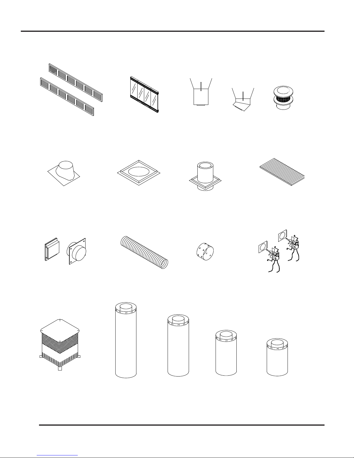
FIREPLACE COMPONENTS
CHIMNEY CAP
COMBUSTION
AK4 OR AK6
CHIMNEY CAP
SC ROUND
MLK36 LOUVER KIT
CF8
S48
S36
S18
S12
FLEX PIPE
UNINSULATED
FP4U OR FP6U
DUCT CONNECTOR
403 OR 603
ASSEMBLY
FA2 FAN
FLASHING
612 OR 1212
GLASS DOOR KIT
MGD36B OR MGD36PB
SPACER
SF FIRESTOP
EXTENSION KIT
H1652 HEARTH
SUPPORT
CHIMNEY
SCS
SE30 30°
ELBOW
AIR ASSEMBLY
THIMBLE
SVTR FIRESTOP
FIGURE 13
12
53D9023
 Loading...