

Martin Fireplaces B36RA, B36LA User Manual
MODELS B36LA AND B36RA
CORNER FIREPLACE
INSTALLATION, OPERATION AND MAINTENANCE MANUAL
FOR RESIDENTIAL INSTALLATION
36 INCH BUILT-IN WOOD
BURNING CORNER
FIREPLACE WITH
OPTIONAL OUTSIDE
AIR AND GLASS
DOORS.
WARNING: THIS FIREPLACE
HAS NOT BEEN TESTED
WITH AN UNVENTED GAS
LOG SET. TO REDUCE RISK
OF FIRE OR INJURY, DO NOT
INSTALL AN UNVENTED GAS
LOG SET INTO FIREPLACE.
53D9041. Rev 1 03/03

CONGRATULATIONS !
You have chosen a fine woodburning fireplace. Your fireplace has been designed and built for years
of heating and viewing enjoyment. Please take time to read this entire manual before installing or
operating your fireplace.
TABLE OF CONTENTS
LISTING AND CODE APPROVALS ................................................................................................................................................. 2
MPORTANT INFORMATION .......................................................................................................................................................... 3
I
O
PERATION GUIDELINES ........................................................................................................................................................... 4
CLEARANCES .......................................................................................................................................................................... 5
IREPLACE COMPONENTS ......................................................................................................................................................... 6
F
F
IREPLACE INSTALLATION ......................................................................................................................................................... 7
HIMNEY COMPONENTS ............................................................................................................................................................ 8
C
S
ELECTING A LOCATION ........................................................................................................................................................... 9
FLOOR PROTECTION .............................................................................................................................................................. 10
LEARANCES ........................................................................................................................................................................ 11
C
F
IREPLACE INSTALLATION .................................................................................................................................................. 12-14
CHIMNEY INSTALLATION ..................................................................................................................................................... 15-16
CHIMNEY OFFSET INSTALLATION .............................................................................................................................................. 17
CHIMNEY OFFSET AND CAP INSTALLATION ............................................................................................................................ 18-19
CHIMNEY CAP INSTALLATION ................................................................................................................................................... 20
OUTSIDE COMBUSTION AIR PRECAUTIONS & RECOMMENDATIONS ................................................................................................. 21
COMBUSTION AIR ASSEMBLY .................................................................................................................................................. 22
GAS APPLIANCE INSTALLATION ........................................................................................................................................... 23-24
TRIM INSTALLATION ........................................................................................................................................................... 24-25
GLASS DOOR INSTALLATION .................................................................................................................................................... 24
FIREPLACE OPERATION ..................................................................................................................................................... 26-27
MAINTENANCE AND SAFETY ................................................................................................................................................ 28-30
PARTS DIAGRAM AND LIST ...................................................................................................................................................... 31
LISTING AND CODE APPROVALS
The instructions contained in this manual provide the information necessary to install this fireplace in accordance with
Underwriter’s Laboratories requirements and in compliance with the National Fire Protection Association Standard No.
21 1. Some codes may require the fireplace and chimney be electrically grounded. Before beginning the installation, you
should check with local building officials to obtain required permits and assure compliance with local regulations and
coded. If you encounter problems with code requirements, contact your dealer for assistance.
The design of this fireplace and these instructions complied with the applicable safety standards for a factory built fireplace
in effect at the time the fireplace was manufactured. You should be aware, however, that failure to install, operate, and
maintain this or any other factory built fireplace properly can result in a house fire or other occurences that could cause
deaths, injuries, and property damages. It is very important that the persons installing and/or supervising the installation
of this fireplace have appropriate skills in using the tools and techniques required: and reading and comprehension skills
sufficient to read and follow these instructions. These instructions contain warnings, cautions, and notes to emphasize
important safety information. To assure that safe and satisfactory service is received from this fireplace, please read the
following special notices and all the contents of this manual.
2
53D9041. Rev 1 03/03

IMPORTANT INFORMATION
1. Read these instructions entirely before beginning any part of the installation. Save these instructions for any
future repairs.
2. Use these instructions as a guide during the installation of the fireplace.
3. Be sure these instructions become the property of and are reviewed by all future users of this fireplace to
encourage proper operation and maintenance.
4. All the parts used with this fireplace system must be installed in accordance with these installation instructions.
Failure to do so may be hazardous and will void the warranty.
5. This fireplace and accessories should not be altered in any way that is not specifically recommended in this
manual.
6. Refer to your local building code for local requirements pertaining to installation of factory-built fireplaces.
Martin Hearth & Heating fireplaces are intended for installation and use according to standard NFPA 211 of the
National Fire Protection Association.
7. This fireplace must not be installed with a masonry flue.
8. This fireplace and chimney should not be used for venting a wood or coal burning heater or fireplace insert.
WARNING: DO NOT INSTALL A SEPARATE SOLID FUEL INSERT OR GAS FIREPLACE INSERT IN THIS FIREPLACE AND CHIMNEY
WITHOUT WRITTEN AUTHORIZATION FROM MARTIN HEARTH & HEATING.
SYSTEM
9. Do not pack required air spaces with combustible material or insulation not specifically recommended for use
in such areas.
Intended Product Usage
This fireplace is intended for supplemental heating only and is not intended for use as a primary heatingsystem.
2
This fireplace is designed to sit directly on a combustible floor. The fireplace can be installed with zero clearances
to combustible building materials at the side, back and top spacers. Only parts manufactured by Martin Hearth &
Heating and labeled for use with this fireplace should be used in the installation of the fireplace except for special roof
flashings that may be fabricated locally. The use of improper parts in the installation can be hazardous and voids the
warranty offered by Martin Hearth & Heating.
This fireplace is designed to burn solid wood fuel (wood).This fireplace is not designed to burn coal, unplumbed liquid
fuels, unplumbed gaseous fuels or household refuse. Any attempt to burn these fuels in the fireplace can be hazardous.
This fireplace is designed for installation in mobile homes if it is installed in accordance with figure 32 in this manual,
which includes using an OAC6 combustion air assembly, WB36LR glass door, SVT firestop thimble, and use either the
LLK or RLK louver kit.
WARNING: DO NOT INSTALL IN A SLEEPING ROOM OF A MOBILE HOME.
CAUTION: IF INSTALLED IN A MOBILE HOME, THE STRUCTURAL INTEGRITY OF THE FLOOR, WALL AND CEILING/ROOF MUST BE MAINTAINED.
WARNING: THIS FIREPLACE AND CHIMNEY MUST NOT BE USED FOR VENTING A SOLID FUEL HEATER OR FIREPLACE INSERT UNLESS
WRITTEN
VOID
improper installation or use of this fireplace will void its warranty and can cause:
1. Damage to the fireplace from overheating.
2. Hazardous temperatures to develop on combustible materials adjacent to the fireplace or chimney.
3. The emission of smoke, sparks or hazardous gases into the dwelling.
4. Leakage of rain water into the dwelling.
AUTORIZATION IS GIVEN BY MARTIN HEARTH & HEATING. FAILURE TO HEED THIS WARNING MAY CAUSE FIRE HAZARD AND WILL
THE WARRANTY.
53D9041. Rev 1 03/03
3

OPERATION GUIDELINES
As wood is burned in the fireplace, room air enters the air slot on the lower front edge and circulates around the
firebox.
The air circulation around the firebox serves to cool the fireplace and must not be blocked in any manner.
Blocking of the inlet slot or outlet louver will cause the firebox to reach hazardous temperatures.
When an OAC4 combustion air assembly and a combustion air duct are attached to the connecting point on
the side of the fireplace, combustion air may enter the firebox through a dampered opening behind the side
panel. This feature is designed for your benefit to reduce the room air used for combustion and to prevent
excessive loss of heat from the room. When the fireplace is in use, this damper should be open. When the
fireplace is not in use, the damper should be closed to prevent cold air from entering the firebox. The combustion
air damper is open when the lever located on the side of the firebox is up and closed when the lever is down.
Outside air for combustion is optional unless required by federal, state or local building codes. See the section
of this manual providing the instructions for installation of the combustion air assembly for additional information.
Glass doors should be installed to receive the maximum benefit from your fireplace. For large fires, the
maximum heating benefit from the fireplace will be obtained with the doors open due to the high amount of
radiant heat being emitted out of the front opening of the fireplace. With a small fire, or before retiring in the
evenings, it is best to operate the fireplace with the doors closed to prevent excessive room air from being
drawn up the chimney. When the doors are open, the mesh screens should be closed to help keep burning
embers from popping out of the firebox.
5
The unique design of the fireplace allows the routing of the combustion air duct downward, horizontally or
upward to obtain the outside combustion air. This permits maximum flexibility in planning your installation. See
figure 22 for typical installation methods. Be sure to review the precautions and recommendations in the
section of this manual pertaining to outside combustion air assembly.
The fireplace also is equipped with a flue damper, which must be open when the fireplace is in use. The flue
damper control lever is located inside the fireplace. The counterweighted damper is operated by simply pushing
up to open or pulling down to close the damper. When the fireplace is not in use, the damper should be closed
to prevent cold air form entering the chimney as well as preventing warm air in the room from escaping up the
chimney . NOTE: It is normal for a small amount of smoke to be released from the upper portion of the fireplace
the first few times you use your new Martin Hearth & Heating fireplace. This results from an oil residue on the
metal. Open a door or window to allow the smoke to escape.
WARNING: Fireplaces equipped with glass doors should be operated only with the glass doors fully open or
fully closed. If doors are left partly open, gas and flame may be drawn out of the fireplace opening, creating
risks of both fire and smoke.
All fireplace chimneys are in direct contact with cold air on the exterior of the structure. Consequently, when
the fireplace is not in use, cold air can fall down the chimney of the fireplace to cool off the fireplace chase.
Therefore, the fireplace chase must be insulated to minimize the risk of cold air infiltration to the home. Even
if the fireplace chase is adequately insulated, this cannot completely ensure that cold air infiltration into the
structure will be eliminated. Cold air infiltration is a possibility with any fireplace or device that freely
communicates with the air on the outside of the structure. Today’s homes are more energy-efficient and,
therefore, better insulated and tightly constructed. Unfortunately, when air is removed from the house, as by
a bathroom fan, or consumed by a furnace, additional air is needed to replace the air consumed. Unless the
additional air is supplied, this can cause a negative pressure in the home. When this happens, the house will
draw in outside air from the cracks in the windows, down the fireplace flue or other locations of air leakage in
the home. Because cold air infiltration may be unavoidable in some structures, Martin Hearth & Heating is not
responsible for heat loss or air infiltration through or around the fireplace.
4
53D9041. Rev 1 03/03
CLEARANCES
6
53D9041. Rev 1 03/03
5
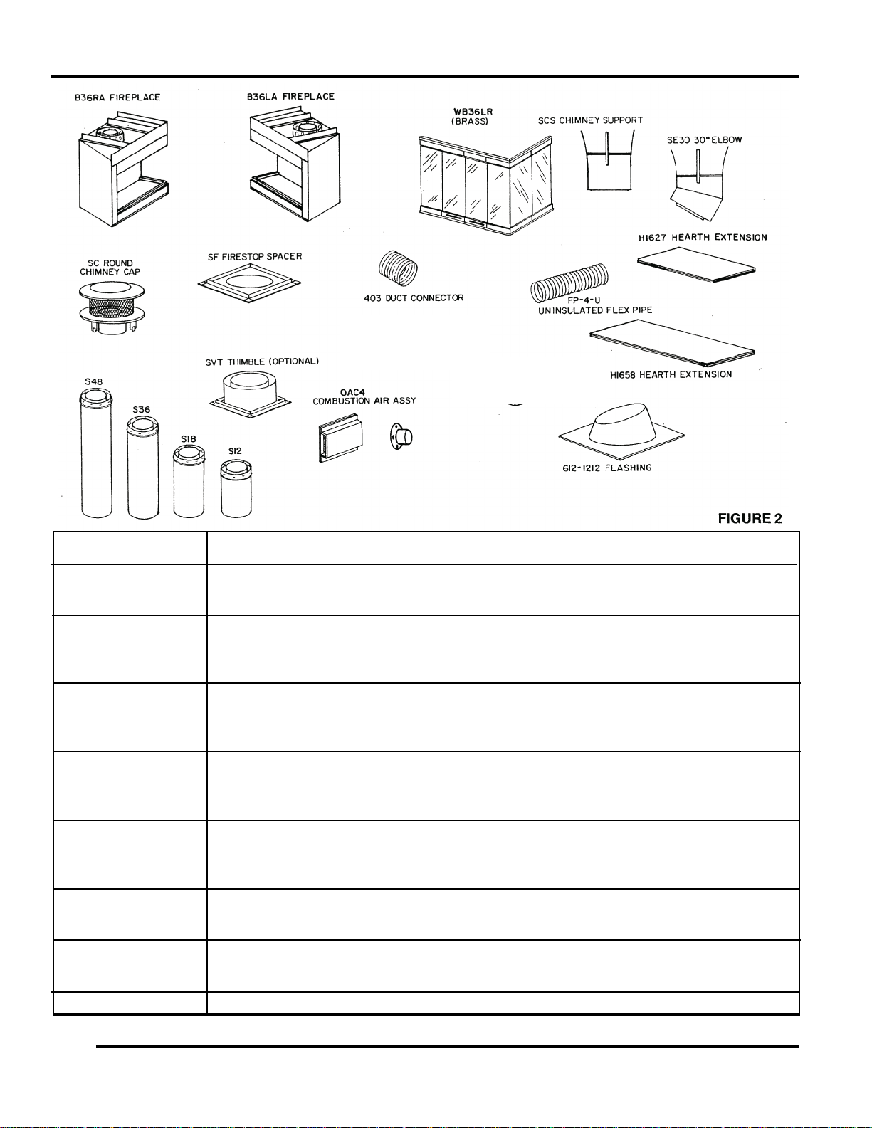
FIREPLACE COMPONENTS
MODEL NUMBER DESCRIPTION
B36LA, B36RA Left or right end open fireplace. Includes wire firescreen, sealing flue damper and
outside combustion air capability. When installed, outside combustion air can be
connected to left side. See installation instruction for details.
S48 4-foot chimney section (8-inch-diameter flue).
S36 3-foot chimney section (8-inch-diameter flue).
S18 1-1/2 foot chimney section (8-inch-diameter flue).
S12 1-foot chimney section (8-inch-diameter flue).
SE30 30-degree elbows (package contains two 8 inch diameter elbows). One pair is required
for each offset. Maximum -- two pairs (4 elbows per chimney).
SCS Chimney support (required when chimney height exceeds 30 feet).
SC Round chimney cap for contemporary installations. Includes storm collar.
SCL Round telescoping chimney cap.
SQL8 Square telescoping chimney cap.
612 0-6/12 pitch flashing for contemporary installation. One required with SC round chimney
cap on 0-6/12 pitch roof.
1212 6/12 - 12/12 pitch flashing for contemporary installation. One required with SC round
chimney cap on 6/12-12/12 pitch roof.
SF 14 1/2” inch firestop spacer --One required at each ceiling or floor level.
SF-30 Firestop spacer - for 30º chimney incline through ceiling or floor.
FP-4-U 4-inch insulated combustion air duct -- 8 foot lengths.
403 4-inch duct connector (for splicing FP-4 ducts). Includes two clamps.
OAC4 4-inches outside combustion assembly.
WB36LR Optional polished brass glass door kit.
H1658 Hearth extension board for front opening. (16” x 58”)
H1627 Hearth extension board for end opening. (16” x 27”)
S8 Telescoping Assembly for use with telescoping chimney caps.
6
53D9041. Rev 1 03/03
FIREPLACE INSTALLATION
53D9041. Rev 1 03/03
7
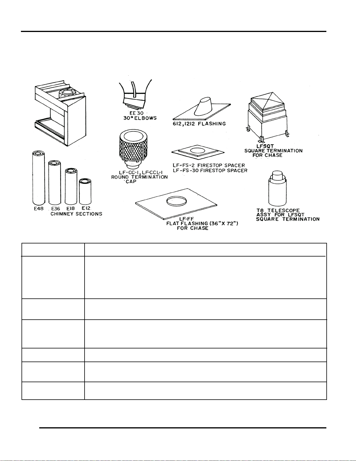
CHIMNEY COMPONENTS
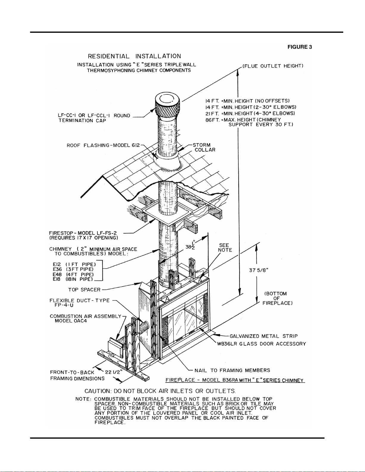
1. When installing “E” series triple wall chimney system on the B36LA and B36LR, do not mix chimney system
components other than those listed below.
2. Maintain 2” airspace clearances to combustibles.
3. Use same offset and rise chart for chimney when installing elbows.
MODEL NUMBER DESCRIPTION
E48 4-foot chimney section (8-inch-diameter flue).
E36 3-foot chimney section (8-inch-diameter flue).
E18 1-1/2 foot chimney section (8-inch-diameter flue).
E12 1-foot chimney section (8-inch-diameter flue).
EE30 30-degree elbows (package contains two 8 inch diameter elbows). One pair is required
for each offset. Maximum -- two pairs (4 elbows per chimney).
ECS Chimney support (required when chimney height exceeds 30 feet).
LFCC-1 Round termination cap for contemporary installation, includes storm collar.
LFCCL-1 Round Termination cap for chase installation (includes inlet air telescope).
612 0-6/12 pitch flashing for contemporary installation. One required with SC round chimney
cap on 0-6/12 pitch roof.
1212 6/12 - 12/12 pitch flashing for contemporary installation. One required with SC round
chimney cap on 6/12-12/12 pitch roof.
LF-FS-2 17” firestop spacer-One required at each ceiling or floor level below 20 foot chimney
height.
LF-FS-30 Firestop spacer-for 30º chimney incline through ceiling or floor.
LFSQT Square termination for chase installation. Model T8 telescope assembly required but not
included.
T8 Telescoping Assembly for use with telescoping chimney caps.
LF-FF Flat flashing for chase installation (36” x 72”).
8
53D9041. Rev 1 03/03
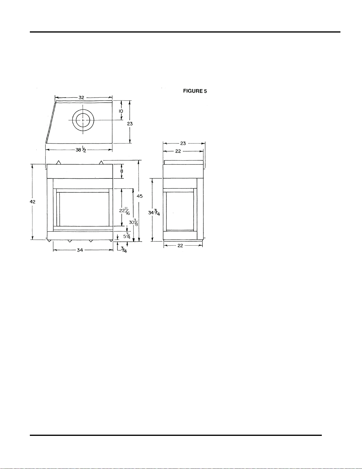
SELECTING A LOCATION
CAUTION: Do not install fireplace over carpeting.
This fireplace does not require any special foundation. If the fireplace is to be trimmed with large stane or brick
facing, an adequate foundation is required to support these materials. Use figures 5 and 6 as a guide for
selecting a location and determining the space required for the fireplace.
The location for the fireplace should be
adjacent to the load bearing wall and away
from objects that will create drafts that could
disturb the normal flow of air into the fire.
Such objects are frequently opened doors
and central heat and air outlets and returns.
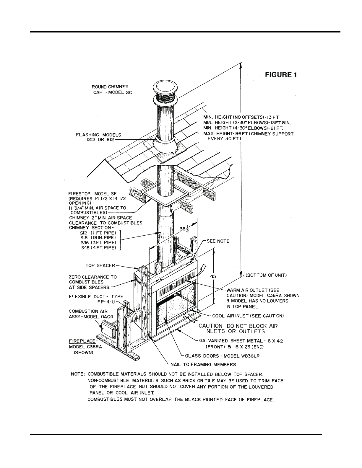
See figure 6 which illustrates various types
of locations and installations and figure 1 for
additional information concerning installation
heights, construction details, and methods
of installation.
A location that requires cutting the least
number of joists and rafters for the chimney
installation will simplify and reduce
installation cost. The opening required for
passage of the chimney through the roof,
ceilings and floors must be 17 inches square
as indicated by figures 7 and 8. The 17-inch
square opening provides for the installation
of the model LF-FS-2 firestop spacer in a
residential installation.
Since the pitch of the roof influences the
opening size required at the roof level, table
1 should be used as a guide for sizing the
roof opening.
Proper selection of a chimney outlet location is also important. Objects such as overhanging or nearby trees,
adjacent building or embarkments or unusual roof designs can all create air turbulance and interfere with
chimney performance and cause the fireplace to spill smoke into the room.
A factory-built fireplace, properly installed in a single story wing of a multi-story builing as shown by figure 9,
may be affected by environmental factors that will cause poor chimney draft and occasional spillage of smoke
from the fireplace opening. Although this occurs infrequently, location of the fireplace in the preferred location
as indicated by figure 9 is recommended.
If the chimney is to pass through living areas or spaces used for storage, be sure that it will be possible to
enclose the chimney to prevent contact with and possible damage to the chimney. Elbows may be used to
avoid obstructions such as electrical wires, water, or sewer pipes, attic fans, heating ducts, etc. Refer to the
section of this manual concerning chimney offsets for proper elbow installation and use.
If the fireplace is to be installed in an outside wall, the surrounding walls should be enclosed and insulated.
failure to properly enclose the fireplace will cause a heat loss and diminish the fireplace efficiency due to
transfer of heat through the fireplace to the outside.
53D9041. Rev 1 03/03
9

FLOOR PROTECTION
All fireplaces installed over a combustible floor must incorporate a non-combustible hearth extension. It is
required to protect the floor in front of the fireplace from both radiant heat and sparks.
Hearth extension dimensions should be determined by using the chart below. use hearth extensions as illustrated in figures 6, 10 and 11 or use an acceptable thickness of a durable non-combustible material with an
equal or greater insulating value than K = .43 Btu in/ft
R = 1.16. These materials should be covered with a decorative non-combustible veneer.
NOTE: Any non-combustible material with a K factor value that is less than .43, or whose R value is more than
1.16 for 1/2” thick material is acceptable.
HOW TO DETERMINE HEARTH EXTENSION REQUIREMENTS
The following information is provided to determine required thickness for any non-combustible material when
either the K or R values are known. They are expressed as the following: K = Btu-in/ft
These materials should be covered by a decorative non-combustible material such as tile, brick, stone or slate.
To determine the thickness needed for a material other than those listed in the chart, use the following formulas
to calculate that which will be an acceptable equivalent.
The ability of insulating material to retard the transfer of heat may be expressed as either Thermal Conductance (C), Thermal Conductivity (K), or Thermal Resistance (R). The mathematical relationship of these
values and the formulas for converting one value to another is as follows:
C = K divided by the material thickness
(Example C = .43 divided by 1/2 (.50)
C = .86)
K = C multiplies by the material thickness
(Example K = .86 multiplied by 1/2 (.50)
K = .43)
R = The material thickness divided by K
(Example R = 1/2 (.50) divided by .43
R = 1.16)
With either type hearth extension minor shifting of the supporting floor or expansion and contraction may
eventually cause a crack to develop between the hearth extension and the face of the fireplace. To help
prevent the crack from developing, the hearth extension materials must be firmly fastened in place. Wall ties
should be screwed to the face of the fireplace and imbedded in the mortar joints of brick, stone, or other noncombustible materials. The metal safety strip packed with the fireplace must be placed beneath the fireplace
and extended under the hearth extension or into a mortar joint of the hearth extension. In the event a crack
does eventually develop, the metal safety strip will serve as a barrier to prevent sparks or embers from falling
from the fireplace onto combustible flooring materials.
* See figure 6A for an alternate hearth extension using brick only.
WARNING: THE CRACK BETWEEN THE HEARTH EXTENSION AND FIREPLACE MUST BE SEALED WITH
A NON-COMBUSTIBLE MATERIAL. WHEN INSTALLING THE HEARTH EXTENSION, BE CAREFUL NOT
TO BLOCK THE HEAT CIRCULATING AIR INLETS (LOUVERS, SLOTS, ETC.). SEE FIGURE 6A.
2
-HR-Fº, or a thermal resistance that equals or exceeds
2
-HR-Fº or R = HR-fº/Btu.
Wall Protection
A model WS wall shield or an equivalent must be installed when the closed end of the fireplace is closer than
24 inches from a wall perpendicular to the face of the fireplace. (see figures 10 and 11). The WS wall shield
should be attached securely to the wall by driving nails or screws through it into the wall studs. The wall shield
should be covered by a decorative non-combustible material such as brick, tile, slate, etc.
The WS wall shield is constructed by 1 inch of Micore CV230 insulation board, manufactured by U.S. Gypsum
Corporation, covered by a sheet of galvanized metal. An alternate insulating material with a K factor of .43 or
lower can be used. refer to the preceeding section for instructions for selecting an alternate insulating material.
WARNING: IF NOT INSTALLED, OPERATED AND MAINTAINED IN ACCORDANCE WITH THE
MANUFACTURER’S INSTRUCTIONS, THIS PRODUCT COULD EXPOSE YOU TO SUBSTANCES IN FUEL
OR FROM FUEL COMBUSTION WHICH CAN CAUSE DEATH OR SERIOUS ILLNESS AND WHICH ARE
KNOWN TO THE STATE OF CALIFORNIA TO CAUSE CANCER, BIRTH DEFECTS OR OTHER REPRODUCTIVE HARM. ALSO, OPERATION, INSTALLATION AND SERVICING OF THIS PRODUCT COULD EXPOSE YOU TO AIRBORN PARTICLES OF GLASS WOOL FIBERS KNOW TO THE STATE OF CALIFORNIA
TO CAUSE CANCER THROUGH INHALATION.
10
53D9041. Rev 1 03/03
 Loading...