

Martin Fireplaces 400BWBCIA, 400BWBCA, 400BWBIA, 400BWBA User Manual

36" and 42"
WOOD BURNING FIREPLACES
INSTALLATION AND OPERATING INSTRUCTIONS
Glass Doors, Fan Assembly, and Outside Combustion Air Kit Available
MODELS:
400BWBA 400BWBIA 400BWBCA 400BWBCIA
500BWBA 500BWBIA 500BWBCA 500BWBCIA
400BWBA and
500BWBA Series
Radiant Type
®
These fireplaces are U. L.
Only Unvented Gas Log Sets which have been found to comply with the Standard For Unvented Room
Heaters ANSI Z21.11.2, are to be installed in this fireplace. A hood must be installed when mantle is
installed at 12” from fireplace opening.
READ BEFORE INSTALLING. SAVE THESE INSTRUCTIONS
listed for use with “S” Series chimney system components.
400BWBCA and
500BWBCA Series
Circulating Type

CONTENTS
CONGRATULATIONS!
You have chosen the finest wood burning fireplace available. Your fireplace has been
designed for years of heating and viewing enjoyment. Please take time to read this entire
manual before installing or operating your fireplace.
Listing and Code Approval ..............................................2
Important Safety Information .......................................... 3
Operation Guidelines ....................................................... 4
How Your Fireplace Should Be Used ........................... 4
How Your Fireplace Works ........................................... 4
Residential Installation ................................................. 4
Glass Doors ................................................................. 4
Flue Damper ................................................................ 4
Grate ............................................................................ 5
Chimneys ..................................................................... 5
Product Features .............................................................. 6
Fireplace Location ............................................................7
Fireplace Dimensions ......................................................8
Installation Preparation.................................................... 9
Floor Protection .............................................................. 11
Fireplace Installation ......................................................13
Unpacking Fireplace .................................................. 13
Clearances ................................................................. 13
Chimney Installation ...................................................... 15
Installing Chimney Safety Information ....................... 14
Locating Center Line .................................................. 17
Installing Firestop Spacer .......................................... 17
Installing “S” Series Chimney Spacers ...................... 18
Installing Chimney Supports ...................................... 19
Elbow Installation ....................................................... 19
Offset Installation Sequence ...................................... 21
Chimney Cap Installation ........................................... 22
Chimney Chase Installation ....................................... 24
Outside Combustion Air Precautions and
Recommendations ................................................... 25
Combustion Air ........................................................... 25
Model AK-4 Combustion Air Assembly ....................... 27
Installing Model 403 Duck Connector ........................ 28
Gas Appliance Installation .............................................
Trim and Mantel Installation ......................................... 31
Gas Appliances .......................................................... 31
Wood Burning Fireplaces ........................................... 32
Glass Door Installation .................................................. 33
Fan Accessory ................................................................ 33
Fireplace Operation ........................................................34
Advantages of a Wood Burning Fireplace ................. 34
Which Woods Are Best .............................................. 34
How to Build a Better Fire .......................................... 34
Wood vs. Fossil Fuels ................................................ 35
A Few Words of Caution ............................................ 35
Maintenance ....................................................................36
Fuel Storage .............................................................. 36
Disposal of Ashes ...................................................... 36
Chimney Maintenance ............................................... 36
Fireplace Maintenance ............................................... 36
Glass Door Maintenance ........................................... 36
Checklist of DOs and DON’Ts .................................... 37
Replacement parts .........................................................39
Warranty .......................................................... Back Cover
28
LISTING AND CODE APPROVALS
The instructions contained in this manual provide the information necessary to install this fireplace in accordance with
Underwriterʼs Laboratories requirements and in compliance with the National Fire Protection Association Standard No. 211.
Some codes may require the fireplace and chimney be electrically grounded. Before beginning the installation, check with
local building officials to obtain required permits and assure compliance with local regulations and codes. If you encounter
problems with code requirements, contact your dealer for assistance.
IMPORTANT: This fireplace is listed by Underwriters Laboratories to U.L. 127 standard for factory-built fireplaces. The design
of this fireplace and these instructions complied with applicable safety standard for a factory built fireplace in effect at the time
the fireplace was manufactured. You should be aware, however, that failure to install, operate, and maintain this or any other
factory built fireplace properly can result in a house fire or other occurrences that could cause deaths, injuries, and property
damages. Persons installing and/or supervising the installation of this fireplace must have appropriate skills in using the tools
and techniques required and have reading and comprehension skills sufficient to read and follow these instructions. These
instructions contain warnings, cautions, and notes to emphasize important safety information. To assure that safe and satisfactory service is received from this fireplace, please read the following special notices and all the contents of this manual.
2 61D0008
IMPORTANT SAFETY INFORMATION
INSTALLER
Please leave these instructions with the owner.
• Read these instructions entirely before beginning any part of the installation. Save
these instructions for any future repairs.
• Use these instructions as a guide during the installation of the fireplace.
• Install all the parts used with this fireplace system in accordance with these installation
instructions. Failure to do so may be hazardous and will void the warranty.
• Do not alter fireplace and accessories in any way that is not specifically recommended
in this manual.
• Refer to your local building code for local requirements pertaining to installation of
factory-built fireplaces. Martin Hearth and Heating fireplaces are intended for installation
WARNING
and use according to standard NFPA 211 of the National Fire Protection Association.
• Do not install fireplace with a masonry flue.
• Do not pack required air spaces with combustible material or insulation not specifically
recommended for use in such areas.
OWNER
Please retain these instructions for future reference
.
This fireplace is NOT designed for installation in manufactured homes without a vented
attic space. Fireplace may be installed in manufactured homes which have a vented
attic space if the fireplace is equipped with GD36BA, GD36PBA, GD36SSA, GD42BA,
GD42PBA or GD42SSA glass doors, an AK6 outside combustion air kit (instead of the
AK4 outside combustion air kit offered for residential type homes as described later
NOTICE
by this instruction manual), a SVTR firestop thimble, and the minimum installed height
from floor to flue outlet is 13'. (See Figure 14, page 16.)
Do not use a fireplace insert or other
product not specified for use with
this fireplace.
CAUTION
Improper installation or use of this fireplace will void its warranty and can cause:
• Damage to the fireplace from overheating.
• Hazardous temperatures to develop on combustible materials adjacent to the fireplace
or chimney.
• The emission of smoke, sparks or hazardous gases into the dwelling.
WARNING
• Leakage of rain water into the dwelling.
61D0008 3

OPERATION GUIDELINES
HOW YOUR FIREPLACE SHOULD BE USED
This fireplace is intended for supplemental heating only and
is not intended for use as a primary heating system.
This fireplace is designed to sit directly on a combustible
floor. The fireplace must be installed with clearances to combustible building materials as specified by this manual. Only
parts manufactured by Martin Hearth and Heating and labeled
for use with this fireplace should be used in the installation
of the fireplace except for special roof flashings that may be
fabricated locally. The use of improper parts in the installation
can be hazardous and voids the warranty offered by Martin
Hearth and Heating.
This fireplace is designed to burn solid wood fuel (wood),
UL- classified processed solid fuel fire logs, or a certified
decorative gas appliance may be installed in the fireplace as
described later by this instruction manual.
This fireplace is not designed to burn coal, unplumbed liquid
fuels, unplumbed gaseous fuels or household refuse. Any
attempt to burn these fuels in the fireplace can be hazard
ous.
HOW YOUR FIREPLACE WORKS
As wood is burned in the fireplace, room air entering the
fireplace is circulated around the fireplace firebox. This air
circulation protects the firebox from overheating. Air circulation through the fireplace must not be blocked or restricted
in any manner. Blocking or restricting air circulation through
the fireplace can cause a fire hazard.
RESIDENTIAL INSTALLATION
air; this permits flexibility in planning your installation. See
Figures 24 thru 27 and their instructions for typical installation of outside combustion air kits. Review the precautions
and recommendations in this manual pertaining to outside
combustion air.
Note: Outside air for combustion is optional in
residential type installations unless required
by local codes. Outside air for combustion
it is mandatory in manufactured home
installations. Use an AK6 outside combustion
air kit in manufactured home installations,
instead of the AK4 offered for residential type
installations.
GLASS DOORS
Glass doors (models GD36BA, GD36PBA, GD36SSA,
GD42BA, GD42PBA and GD42SSA by Martin Hearth and
Heating) may be installed to receive the maximum benefit
from your fireplace. For large fires, the maximum heating
benefit from the fireplace will be obtained with the doors open
due to the high amount of radiant heat being emitted out of
the front opening of the fireplace. With a small fire, or before
retiring in the evenings, it is best to operate the fireplace with
the doors closed to prevent excessive room air from being
drawn up the chimney. When the doors are open, the mesh
screens should be closed to help keep burning embers from
popping out of the firebox.
Note: Glass doors are mandatory on fireplaces
installed in manufactured homes.
In residential type installation, an AK4 outside combustion air
kit may be connected to the left side of the fireplace to allow
outside air to enter the firebox through a dampered opening in
that side of the fireplace. This outside combustion air feature
reduces the room air used for combustion and prevents exces
sive heat loss from the room. When the fireplace is in use,
the fireplaceʼs “outside combustion air” damper connected
to an AK4 may be opened to allow air from outside to enter
the fireplace firebox. When the fireplace is not in use, the
“outside combustion air” damper should be closed to prevent
cold air from entering the firebox. An “outside combustion
air” damper is open when its control lever is up and closed
when its control lever is down. A control lever for the outside
combustion airdamper is located inside the firebox near the top
of the side firebrick on the left side of the fireplace. The design
of the fireplace allows the routing of the combustion air duct
downward or horizontally to obtain the outside combustion
4 61D0008
-
Fireplaces equipped with glass doors
should be operated only with the
glass doors fully open or fully closed.
If doors are left partly open, gas and
flame may be drawn out of the fireplace
opening, creating risks of both fire and
WARNING
smoke.

OPERATIONAL GUIDELINES
FLUE DAMPER
The fireplace also is equipped with a flue damper which must
be open when the fireplace is in use. The flue damper control
lever is located inside the fireplace. The counterweighted
damper is operated by simply unlocking up to open or pulling
and locking down to close the damper. When the fireplace is
not in use, the damper should be closed to prevent cold air
form entering the chimney as well as preventing warm air in
the room from escaping up the chimney.
Note: It is normal for a small amount of smoke to
be released from the upper portion of the
fireplace the first few times you use your
new Martin Hearth and Heating fireplace.
This results from an oil residue on the metal.
Open a door or window to allow the smoke
to escape.
GRATE
The grate included with this fireplace helps to appropriately
locate and contain the burning wood.
Failure to use this grate may cause
overheating of parts of the fireplace
and allow large pieces of burning
wood to roll forward out of the firebox.
Replace warped or damaged grate
only with a Martin Hearth and Heating
WARNING
grate.
CHIMNEYS
All fireplace chimneys are in direct contact with cold air on the
exterior of the structure. Consequently, when the fireplace is
not in use, cold air can fall down the chimney of the fireplace
to cool off the fireplace chase. Therefore, the fireplace chase
must be insulated to minimize the risk of cold coming into
the home. Even if the fireplace chase is adequately insulated,
this cannot completely ensure that cold air coming into the
structure will be eliminated. Cold air coming inside is a possibility with any fireplace or device that freely uses air on the
outside of the structure. Todayʼs homes are more energy-efficient and, therefore, better insulated and tightly constructed.
Unfortunately, when air is removed from the house (by a
bathroom fan or consumed by a furnace) additional air is
needed to replace the air consumed. Unless the additional air
is supplied, this can cause a negative pressure in the home.
When this happens, the house will draw in outside air from
the cracks in the windows, down the fireplace flue or other
locations of air leakage in the home. Because cold air coming
in may be unavoidable in some structures, Martin Hearth
and Heating is not responsible for heat loss or air infiltration
through or around the fireplace.
61D0008 5
PRODUCT FEATURES
PRODUCT SPECIFICATIONS
• This fireplace is designed to burn solid wood fuel (wood), UL-classified processed solid fuel fire logs, or a certified
decorative gas appliance may be installed in the fireplace as described later by this instruction manual.
• The appliance must be properly connected to a venting system.
Optional
Fan
Switch
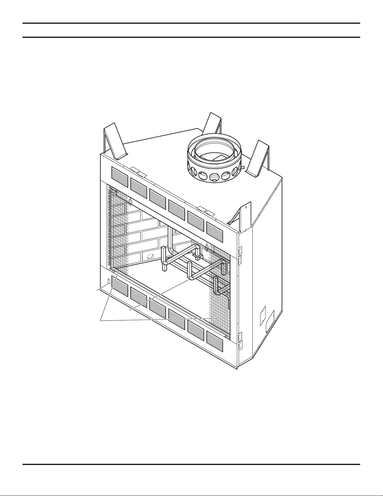
Screens
Grate
Figure 1 - Wood Burning Fireplace
(Circulating Unit Shown)
6 61D0008
FIREPLACE LOCATION
Plan for the installation of your fireplace. This includes determining
where the unit is to be installed, the vent configuration to be used, framing
and finishing details, and whether any optional accessories (i.e. blower,
wall switch, or remote control) are desired. Consult your local building
code agency to ensure compliance with local codes, including permits
and inspections.
The following factors should be taken into consideration:
• This fireplace should have sufficient access for its safe operation and maintenance.
• Locate a position where the flue system of the fireplace can be properly installed without damaging the integrity
of the building. e.g. cutting wall or ceiling joist (example: load-bearing framing members).
• Install floor protection when the appliance is installed directly on tile or other combustible material.
• Check fireplace and flue system clearance requirements.
• Locate the fireplace in a large and open room that is centrally located in the house. This will optimize heat
circulation and comfort.
• Locate fireplace away from frequently opened doors, central heat outlets or returns, or other places where air
movements may disturb the airflow around the fireplace.
Note: Air turbulence near the fireplace may cause smoke to spill out of the fireplace opening.
Do not install fireplace
over carpeting.
CAUTION
• Locate fireplace near a load bearing wall. Make sure the support structure is strong enough or reinforced if
fireplace is to be trimmed with a heavy stone or brick facing and hearth extension.
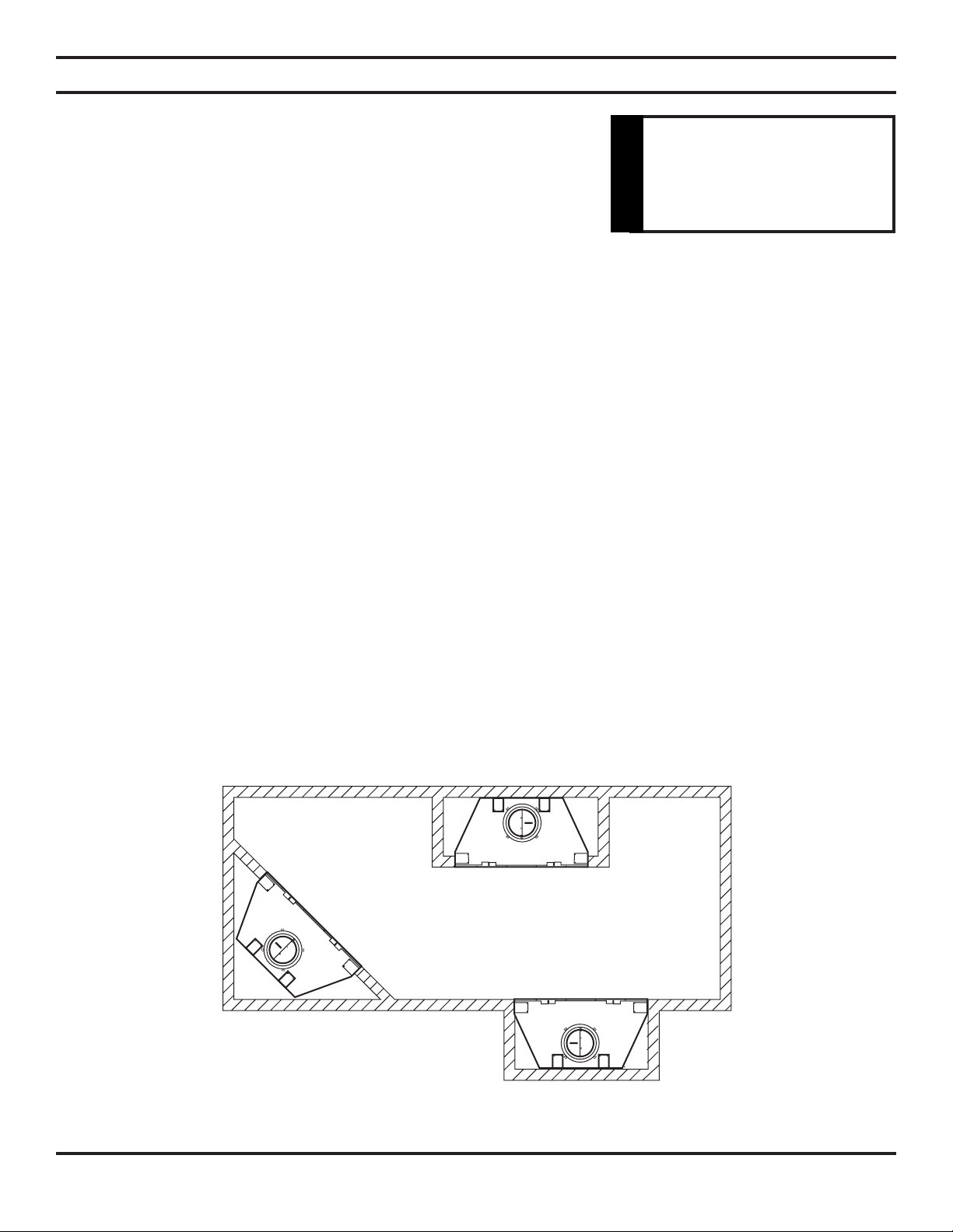
• This fireplace may be installed along a wall, across a corner, or use an exterior chase. See Figure 2 for suggested locations.
• Location should be out of high traffic areas and away from furniture and draperies.
• Never obstruct the front opening of the fireplace.
• Do
• Vent pipe routing. See Venting section found in this manual for allowable venting configurations.
• Minimum clearances to combustibles, side-wall, ceiling, woodwork, and windows must be maintained. See Clearances
not install in the vicinity where gasoline or other flammable liquids are stored.
Section in this manual.
Figure 2 - Suggested Fireplace Locations
61D0008 7
A
7
1
/2"
6
1
/2"
6
1
/2"
34
3
/8"
1
/2" or 5/8"
Drywall Spacers
21"
10"
13
1
/2"
21
1
/2"
2
5
/8"
17
1
/4"
7"
8
7
/8"
Gas
9
5
/8"
Air Kit
1
/2" or 5/8"
Drywall
Spacers
13
3
/4"
Electrical
21
3
/4"
Framing
Dimension
40
3
/4"
Framing
Dimension
C
Framing Dimension
B
TOP VIEW
FRONT VIEW SIDE VIEW
400BWBA 400BWBCA
400BWBIA 400BWBCIA
500BWBA 500BWBCA
500BWBIA 500BWBCIA
Outside
Connector
Center
Line
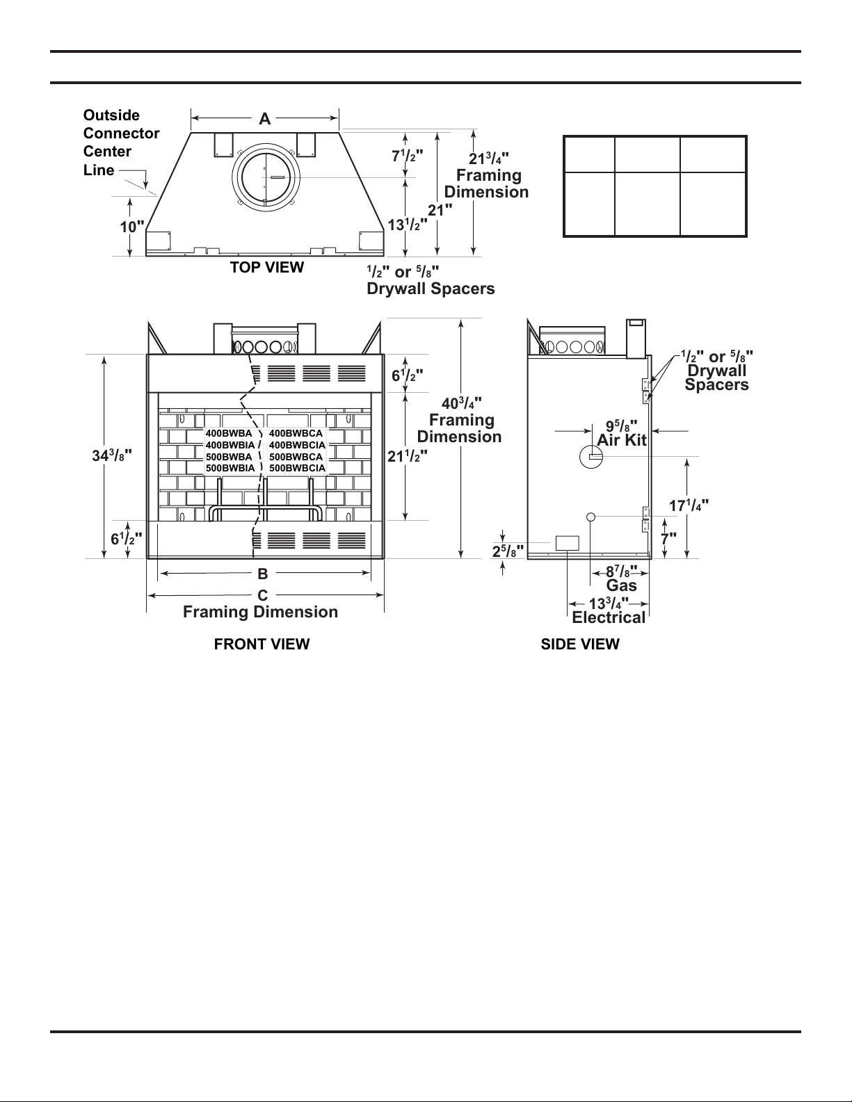
FIREPLACE DIMENSIONS
400 500
Units Units
A 243/4" 303/4"
B 36" 42"
1
C 40
/2" 461/2"
Figure 3 - Fireplace Dimensions
8 61D0008
INSTALLATION PREPARATION
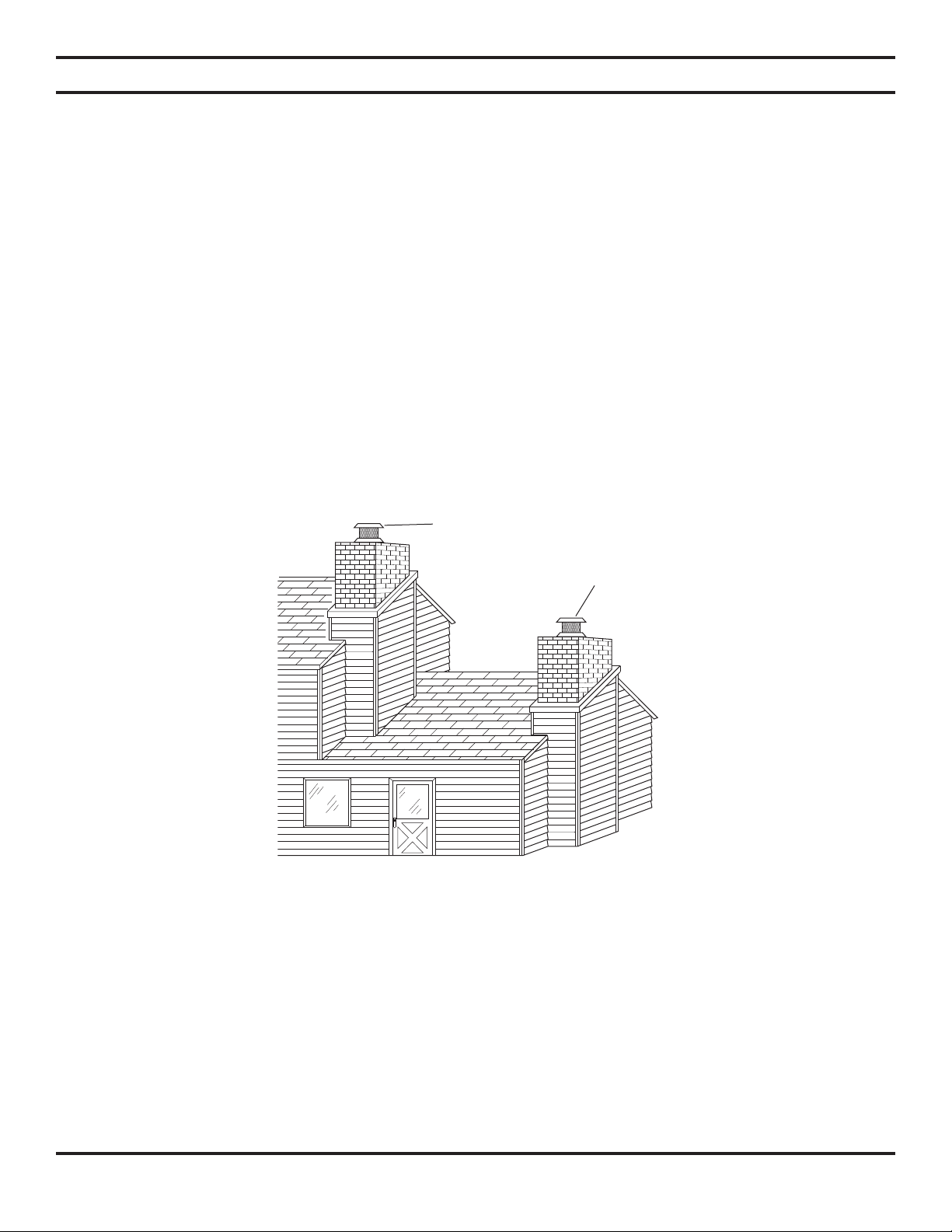
LOCATING CHIMNEY
• Survey the planned location for the fireplace for overhead plumbing or electrical wires, etc. This could make installation
harder. It could also be a hazard for persons installing or cleaning the chimney.
• Do not install where the chimney cap will be near abrupt changes in the roof shape, nearby wall or embankments, under
or near trees or above the roof of a single story wing of a two story building. See Figure 4. Any of these conditions may
cause turbulence or pressure condition which may create poor chimney draft and smoke spillage from the fireplace opening into the home.
• Use elbows to offset the chimney to avoid obstructions or to locate the chimney cap in a better location. See Chimney
Offsets Section on pages 18 and 21 for instructions on proper elbow use. Poor installation or location of the chimney cap
and/or components can cause wind blown rain to enter the chimney.
• The selected location must have a 15" square combustible material-free space for the chimney to pass through.
• If the chimney is to pass through living or storage spaces, there must be adequate space to enclose the chimney to avoid
personal contact with, or damage to, the chimney.
Continued
Preferred
Location
Poor
Location
Figure 4 - Preferred Chimney Location
61D0008 9
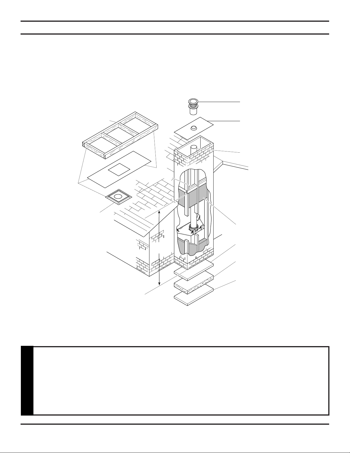
SCL Telescoping
Chimney Cap
Flat Chase Flashing
R3672 (36"x72")
or
R4884 (48"x84")
Chimney Sections
“S” Series
Insulate Outside
Walls of Chase
Solid Continuos
Surface
Insulation
(Thermal Barrier)
Outside Base
Solid
Surface
8'0"
Level
Joist Insulate
Same as Ceiling
See
Warning
Below
SF Firestop
Spacer
INSTALLATION PREPARATION
LOCATING CHIMNEY (CONTINUED)
• If the fireplace is to be installed on an outside wall, the surrounding walls (chase) must be constructed and insulated.
See Figure 5. If you do not insulate the fireplace from outside temperatures, heat loss through and around the fireplace
will occur.
• You must use Model SF Firestop
• It is recommended for safety and reducing heat loss that firestopping be used at the
• Do not insulate chase with blown or fill type insulation. Only allow insulation to come
WARNING
Figure 5 - Installing Fireplace on an Outside Wall
ceiling level for chase installation even if local codes do not require firestopping.
into contact with fireplace at points where fireplace would normally be contacted by
framing materials.
10 61D0008
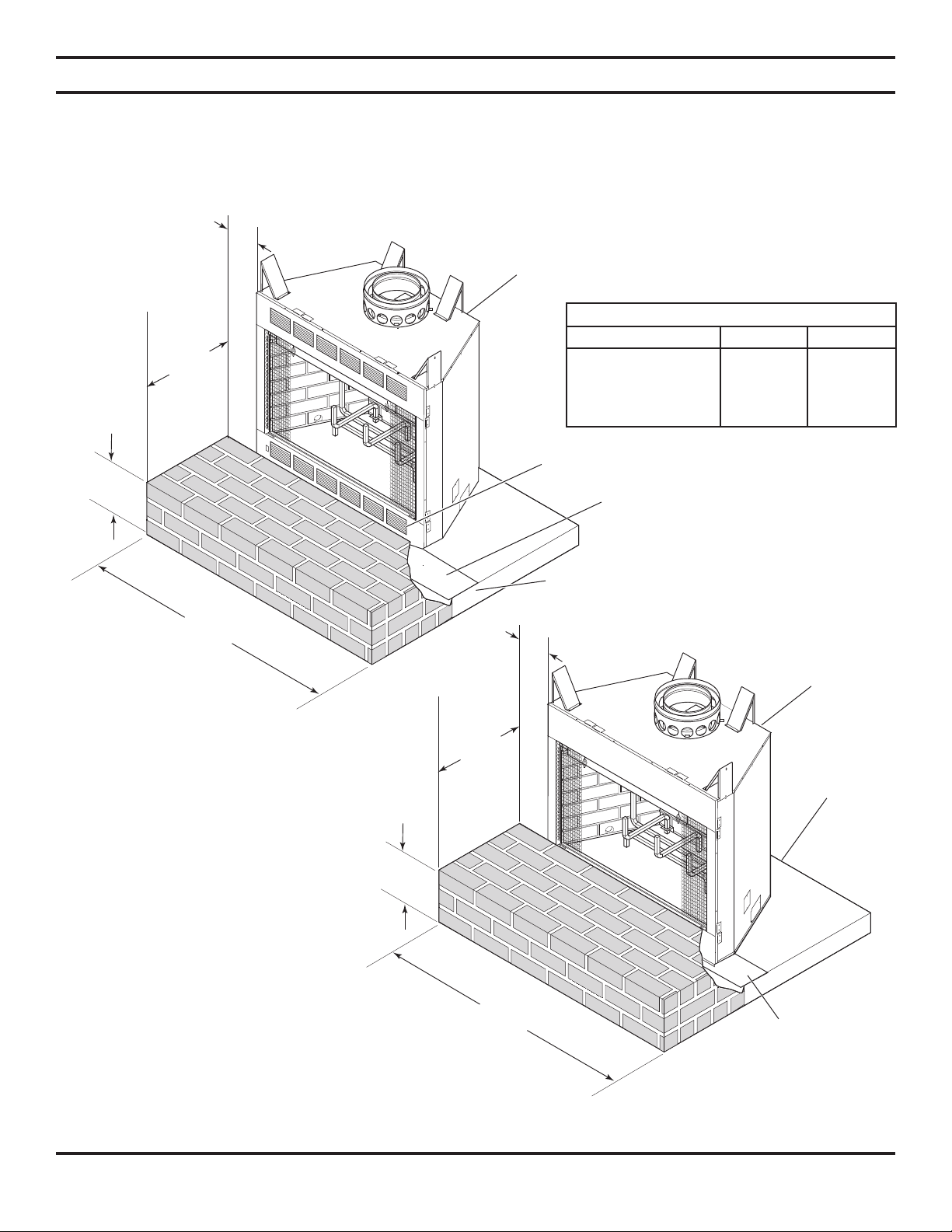
8"
Min.
6" Min. Brick
or Stone
from Top
of Platform
Brick or Stone Hearth Extension
52" (400 Models)
66" (500 Models)
16" Min.
(400 Unit)
20" Min.
(500 Unit)
8"
Min.
6" Min. Brick
or Stone
from Top
of Platform
Brick or Stone Hearth Extension
52" (400 Models)
66" (500 Models)
16" Min.
(400 Unit)
20" Min.
(500 Unit)
FLOOR PROTECTION
INSTALLING FIREPLACE ON COMBUSTIBLE FLOOR
If fireplace is installed on a combustible floor, protect the floor area either side of the fireplace opening and in the front
with an insulating non-combustible hearth extension. (16" [400 unit] or 20" [500 unit] minimum in front of fireplace and
8" minimum on both sides. See Figures 6 through 12.
Fireplace
Hearth Extension Clearances & Width
400 Unit 500 Unit
On Both Sides 8" Min. 8" Min.
Front of Fireplace 16" Min. 20" Min.
Extension Width 52" 66"
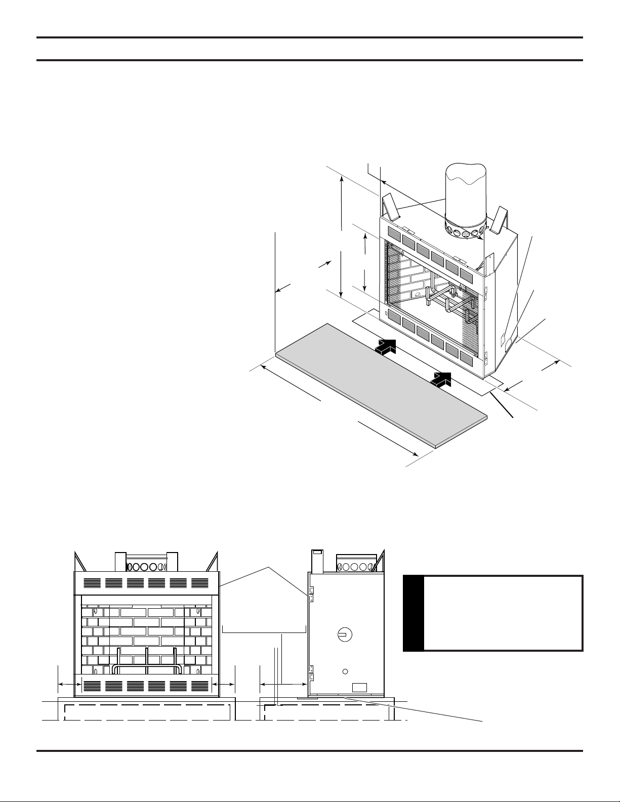
Air Vents — DO NOT BLOCK
Metal Safety Strip Must Be
Use if Unit Is Placed on
Combustible Floor
Figure 6 - Installing Floor
Protection (Circulating Model)
Note: Do not block the side air
vents or air inlet louvers on
the lower front of the fireplace
with hearth extension.
Air vents and air inlet louvers allow
necessary cooling air around the fireplace. Determine the finished height of
the hearth extension to be used. Raise
the fireplace on a platform, if necessary,
to prevent blocking of air openings and
lower louvered panel.
Note: No platform is needed if
hearth extension does
not exceed 1" thick for
circulating units or 6½" for
radiant units.
61D0008 11
Platform May Extend Under Hearth
Extension if Desired
Fireplace
Platform
(If Necessary)
Metal Safety Strip
Must Be Use if
Unit Is Placed on
Combustible Floor
Figure 6 - Installing Floor Protection (Radiant Model)
52" (400 Models)
66" (500 Models)
Safety Strip
3"x36" Min. (400 Unit)
3"x42" Min. (500 Unit)
16" Min.
(400 Unit)
20" Min.
(500 Unit)
21"
211/2"
40
1
/2"
40
1
/8" (400 Unit)
46
1
/8" (500 Unit)
16"min. - 400 unit
20" min. - 500 unit
8"8"
FLOOR PROTECTION
INSTALLING FIREPLACE ON COMBUSTIBLE FLOOR (CONTINUED)
This hearth extension must be either 6" (minimum) thick stone or brick; a H1652 (400 units) or H2066 (500 units) Hearth
Extension Kit; or a locally constructed hearth that has a “K” factor less than .43 and at least ½" thick. For other non-combustibles, the total thickness minimum is 1.16 times its thermal conductivity (K).
The following relations could be useful —
C = K divided by the material thickness
(Example C = .43 divided by 1/2 (.50)
C = .86)
K = C multiplies by the material thickness
(Example K = .86 multiplied by 1/2 (.50)
K = .43)
R = The material thickness divided by K
(Example R = 1/2 (.50) divided by .43
R = 1.16)
C = Thermal Conductant
R = Thermal Resistance
Minor shifting of the supporting floor or
expansion and contraction may eventually
cause a crack to develop between the hearth
extension and the face of the fireplace with
either type hearth extension. To help prevent
the cracking, firmly fasten the hearth extension
materials in place. Screw wall ties to the face of
the fireplace. Imbed the wall ties in the mortar
joints of brick, stone, or other non-combustible
materials.
Gas
Opening
Junction
Box
Opening
Floor
Level
Place metal safety strip packed with the
fireplace beneath the fireplace. Extend metal
safety strip under the hearth extension or into
a mortar joint of the hearth. See Figures 6
through 9. If a crack does eventually develops,
the metal safety strip will prevent sparks or
Figure 8 - Installing Hearth Extension
(Circulating Model Shown)
embers from falling from the fireplace onto
combustible flooring materials.
Fireplace
Hearth
Only install metal safety
strip horizo ntal to the
fireplace.
WARNING
Metal
12 61D0008
Figure 9 - Installing Hearth Extension and Metal Safety Strip
Safety Strip
213/4"min
13"min
FIREPLACE INSTALLATION
UNPACKING FIREPLACE
Unpack and check the fireplace and chimney for damage. If any items are been damaged or missing, contact your Martin Hearth
and Heating dealer. Do not substitute parts. Use only parts listed for use with Martin Hearth and Heating Models 400BWBA,
400BWBIA, 400BWBCA, 400BWBCIA. 500BWBA, 500BWBIA, 500BWBCA and 500BWBCIA fireplaces.
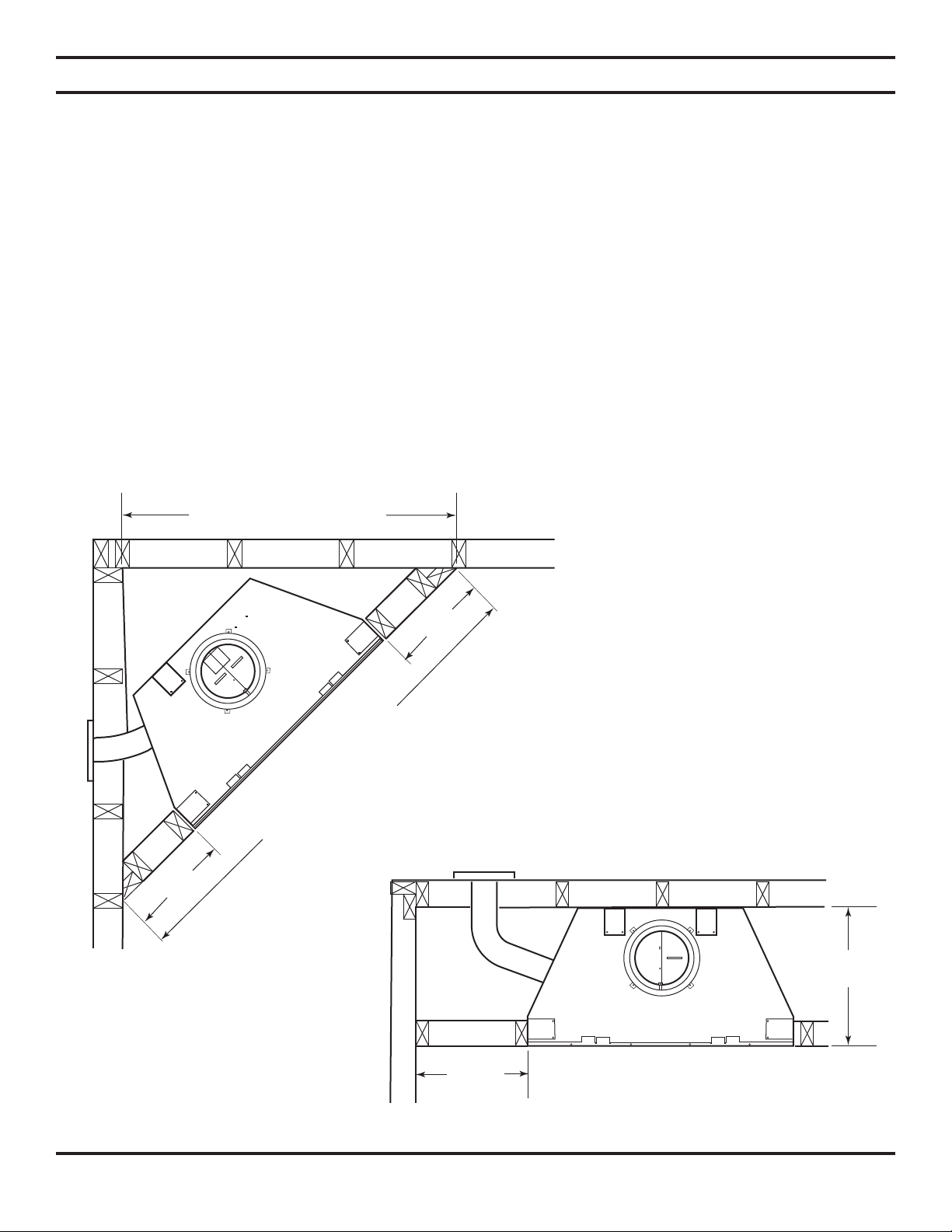
CLEARANCES
1. Provide required clearances shown in Figures 10 through 12. Provide 2" minimum chimney air space clearance to com-
bustibles.
2. Place fireplace in the desired location. Securely support and level fireplace. Check face of the fireplace with a carpenterʼs
level. If fireplace is not plumb, correct it by placing shims under the edges of fireplace.
3. Block in the fireplace to prevent any shifting of firebox. Secure fireplace with nails or screws through the flanges located on
each side of the fireplace. Do not enclose the fireplace until the combustion air duct and chimney pipes are installed.
Note: Some local codes may require electrically grounding the fireplace and chimney.
Continued
Figure 10 - Minimum Clearances for Corner
Installation
61D0008 13
Figure 11 - Minimum Clearances for Wall Installation
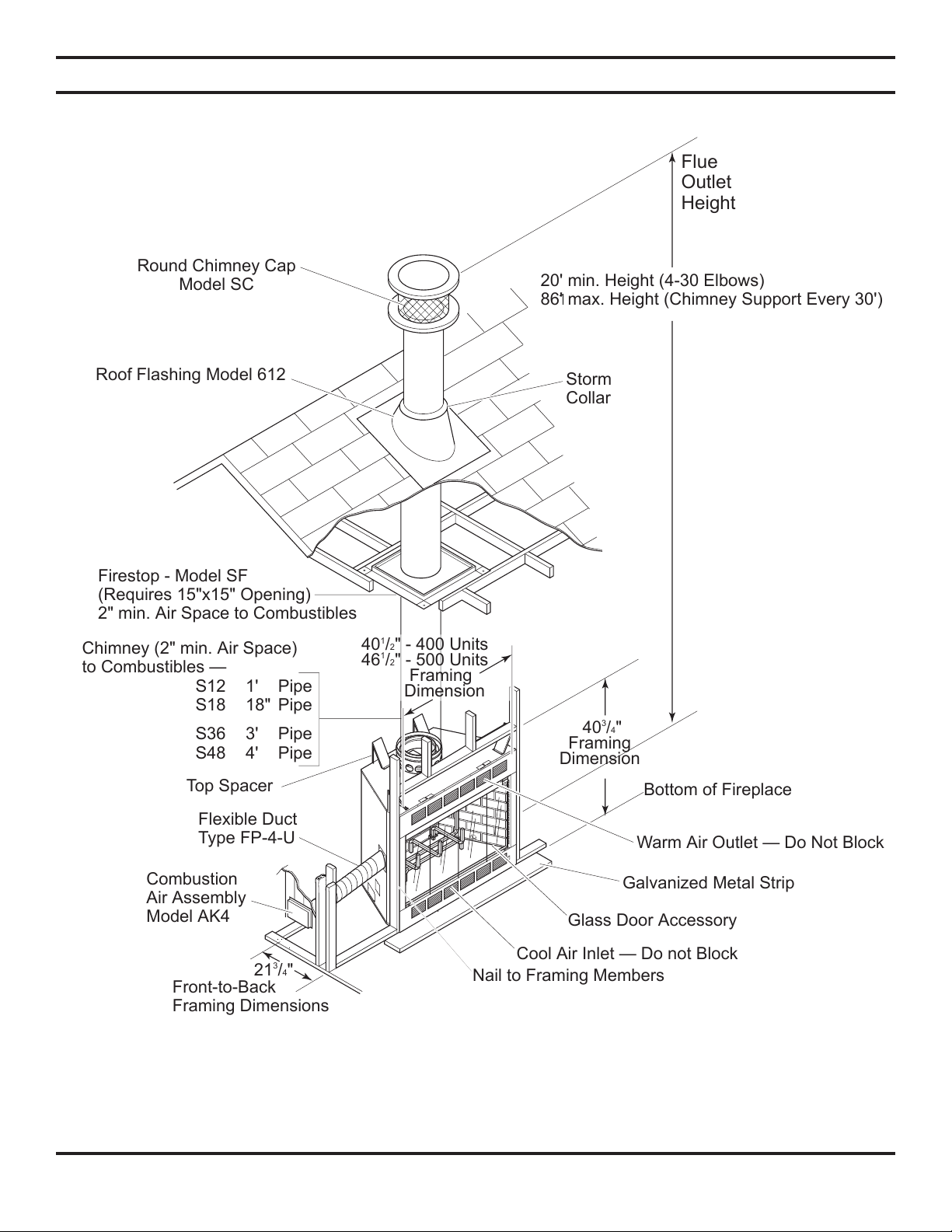
20' min. Height (4-30 Elbows)
86' max. Height (Chimney Support Every 30')
Storm
Collar
Bottom of Fireplace
Warm Air Outlet — Do Not Block
Galvanized Metal Strip
Glass Door Accessory
Cool Air Inlet — Do not Block
Nail to Framing Members
Round Chimney Cap
Model SC
Flue
Outlet
Height
Roof Flashing Model 612
Firestop - Model SF
(Requires 15"x15" Opening)
2" min. Air Space to Combustibles
Top Spacer
Flexible Duct
Type FP-4-U
Combustion
Air Assembly
Model AK4
Front-to-Back
Framing Dimensions
403/4"
Framing
Dimension
401/2" - 400 Units
46
1
/2" - 500 Units
Framing
Dimension
21
3
/4"
Chimney (2" min. Air Space)
to Combustibles —
S12 1' Pipe
S18 18" Pipe
S36 3' Pipe
S48 4' Pipe
FIREPLACE INSTALLATION
CLEARANCES CONTINUED
Figure 12 - Proper Clearances and Chimney Height
14 61D0008
 Loading...