

Page 1

PROVING UNITS
Instruction
Manual
PD430
PD440
PD690
PD700
PD710
ALWAYS READ THESE INSTRUCTIONS BEFORE PROCEEDING
Thank you for buying one of our products. For safety and full
understanding of its benefits please read this manual before use.
Technical support is available from 01923 441717 and
[email protected].
CONTENTS
1 Safety Information 1
1.1 Meaning of Symbols and Markings 1
1.2 Precautions 2
2 Introduction 3
2.1 Inspection 3
2.2 Description 3
2.3 Accessories 4
2.4 Battery Installation 4
3 Operation 5
3.1 Proving Unit LED Indications 5
3.2 Using the External Power Socket 5
3.3 Proving a Test Lamp, Voltage Tester/Indicator, DMM, etc. 7
3.4 Test Lamp, Voltage Tester/Indicator Cables 7
4 Maintenance 8
4.1 Battery Replacement 8
4.2 Cleaning 8
4.3 Repair and Service 8
4.4 Storage Conditions 9
1 SAFETY INFORMATION
REMEMBER: SAFETY IS NO ACCIDENT
These instructions contain both information and warnings that are
necessary for the safe operation and maintenance of this product. It
is recommended that you read the instructions carefully and ensure
that the contents are fully understood. Failure to understand and
to comply with the warnings and instructions can result in serious
injury, damage or even death.
Particular attention should be paid to the Warnings, Precautions and
Technical Specifications.
Please keep these instructions for future reference.
Updated instructions and product information are available at:
www.martindale-electric.co.uk
1.1 Meaning of Symbols and Markings
Caution - risk of danger & refer to instructions
Caution - risk of electric shock
Equipment protected by double or reinforced
insulation (Class II)
Equipment complies with relevant EU Directives
End of life disposal of this equipment should be in
accordance with relevant EU Directives
5 Warranty 10
Specifications
1.2 Precautions
This product has been designed with your safety in mind, but please
pay attention to the following warnings and cautions before use.
Warnings
In order to avoid the danger of electrical shock, it is important that
proper safety measures are taken when working with voltages
exceeding 30V AC rms, 42V AC peak or 60V DC.
Before use check the unit for cracks or any other damage. Make
sure the unit is free from dust, grease and moisture. Also check any
associated accessories for damage. Do not use if damaged.
Do not use if the battery cover is not fitted.
Do not apply greater than 12V DC to the external power socket.
Cautions
Avoid severe mechanical shock or vibration and extreme temperature.
To avoid corrosion from leaking batteries, remove the batteries when
the unit is not in use for an extended period.
Limit the test time to less than 10 seconds.
Do not short the output terminals.
1
2
Page 2

2. INTRODUCTION
2.1 Inspection
Examine the shipping carton for any sign of damage. Inspect the unit
and any accessories for damage. If there is any damage then consult
your distributor immediately.
2.2 Description
PD430 & PD440
The PD430 & PD440 are portable battery powered proving units for
the testing of contact type voltage detectors up to 440V.
The PD430 is a dual voltage proving unit which generates 50V at
50Hz for 3 seconds and then generates 440V at 50Hz. The PD440
generates 440V only at 50Hz.
Low
Voltage
LED
Model
PD430
PD440
PD690
PD700
PD710
Low
High
Voltage
Voltage
Frequency
50V 440V 50Hz
440V 50Hz
700V 50Hz
50V 700V 50Hz
700V DC
Output
2.3 Accessories
All units come with the following accessories:
6 x 1.5V AA alkaline batteries
Instructions
Low
High
High
Battery
Current
Voltage
LED
Neon
LED
PD690 & PD700
The PD690 & PD700 are portable battery powered proving units for
the testing of contact type voltage detectors up to 700V.
The PD700 is a dual voltage proving unit which generates 50V at
50Hz for 3 seconds and then generates 700V at 50Hz. The PD690
generates 700V only at 50Hz.
PD710
The PD710 is a portable battery powered proving unit for the testing of
contact type voltage detectors up to 700V.
The PD710 generates 700V DC only.
3. OPERATION
Caution
Always make sure the precautions and limitations of the unit being
tested are observed. If necessary refer to the specification of the
unit being tested.
Accessories not included:
PSUPD230 - mains powered 12V DC power supply
PSUHPAT12 - 12V DC in car fused charger adaptor
2.4 Battery Installation
Refer to Section 4.1 (Battery Replacement) for the battery installation
instructions for all units.
3
4
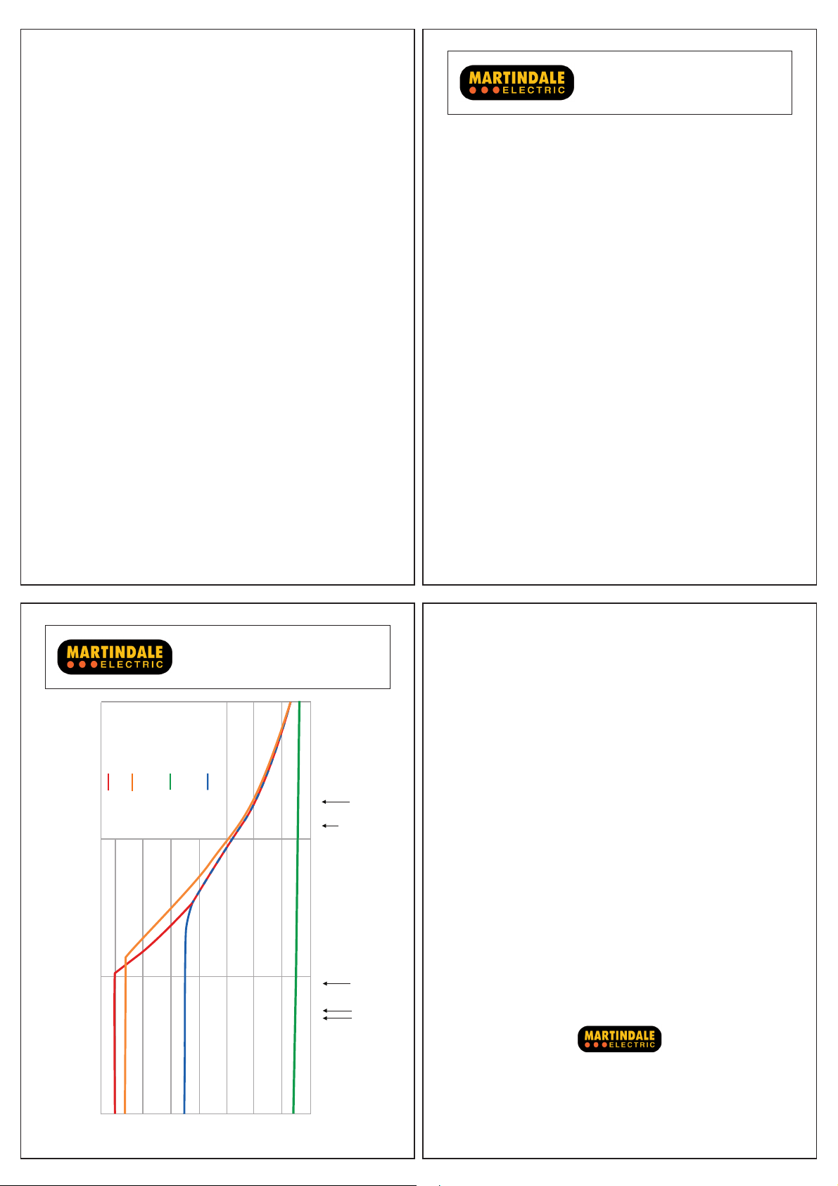
Also refer to the graph of typical output voltage under various load
conditions at the rear of these instructions.
3.1 Proving Unit LED indications
LED Proving unit model No. LED illumination indicates
Low Voltage PD430 & PD700
High Voltage All models
Low Battery All models
High Current * PD700
50V output at proving unit
terminals for approx. 3 seconds
High voltage output at proving
unit terminals
Proving unit batteries are low
Replace batteries
UUT current consumption
> 5mA
* Typically Martindale voltage indicators draw < 3.5mA but other
manufacturers’ instruments may vary.
3.2 Using the External Power Socket
An external power jack socket is provided, allowing the use of an
external 12V DC power source instead of the internal batteries.
Remove the rubber shroud from the jack socket access hole, and
plug in a 12V DC source (2A minimum) using a 2.5mm jack plug
(centre positive).
External power
socket
If internal batteries are fitted they will be disconnected by the
insertion of the jack plug. If however, the internal batteries are not
the intended primary power source, it is advisable to remove them
to prevent damage from leaking batteries.
It is advisable to replace the rubber shroud after use to prevent the
ingress of dust and moisture.
Two suitable units available from Martindale Electric for providing
external power are the:
PSUPD230, a mains powered, 12V DC power supply;
PSUHPAT12, a12V DC in car fused adaptor.
5
6
Page 3

3.3 Proving a Test Lamp, Voltage Tester/Indicator, DMM etc.
Place one probe of the unit under test into the left hand socket of
the proving unit until it makes contact with the terminal. Place the
other probe into the right hand terminal of the proving unit and
gently press down.
On the PD440 and PD690 the high voltage indicator will illuminate.
On the PD430 and PD700 the low voltage indicator will illuminate
for 3 seconds, then the high voltage indicator.
Observe that the required indicators on the unit under test
illuminate, then withdraw the probe from the right hand terminal first,
and then the left.
Do not operate the proving unit for periods longer than 10 seconds.
If none of the proving unit LED’s illuminate when performing the
above tests check the condition of the proving unit batteries and
replace them if required (see section 4.1).
3.4 Test Lamp, Voltage Tester/Indicator Cables
During the above tests, emphasis should also be placed upon the
flexing of the UUT cable along its length, and particularly at the
entry points to the hand held elements, to confirm that the cable has
not fractured.
It may be necessary to perform this test a number of times so as not
to operate the proving unit for longer than 10 seconds in any one
test episode.
4. MAINTENANCE
4.1 Battery Replacement
Remove the rear battery cover by unscrewing the screw at the end of
the cover. The screw is captive but once it is loose the cover can be
slid downwards beyond the bottom end of the unit and lifted clear.
Observing correct polarity fit 6 new 1.5V, AA alkaline batteries (IEC
LR6, NEDA 15A).
Replace the battery cover by positioning it into the rear casing slots
and sliding it upward into position, then tighten the screw. Do not
over-tighten.
Note: Do not mix old and new batteries.
4.2 Cleaning
If contamination is found, clean with a damp soft cloth and if
necessary a mild detergent or alcohol. Do not use abrasives,
abrasive solvents, or detergents which can cause damage to the
unit. If a mild detergent is used, the unit should subsequently be
thoroughly cleaned with a water dampened soft cloth. After cleaning,
dry and allow to remain in a dry environment for 2 hours before use.
4.3 Repair and Service
There are no user serviceable parts in this unit other than those that
may be described in section 4. Return to Martindale Electric if faulty.
Our service department will quote promptly to repair any fault that
occurs outside the guarantee period.
Before the unit is returned, please ensure that you have checked the
unit and batteries.
4.4 Storage Conditions
The instrument should be kept in cool, dry conditions and not
subjected to shock, scratching or other damage, prolonged direct
harsh sunlight, extremes of temperature and in such a manner as
to preserve the working life of the unit. It is strongly advised that the
unit is not kept in a tool box where other tools may damage it.
7
8
5. WARRANTY AND LIMITATION OF LIABILITY
This Martindale product is warranted to be free from defects in
material and workmanship under normal use and service. The
warranty period is 2 years and begins on the date of receipt by the
end user. This warranty extends only to the original buyer or enduser customer, and does not apply to fuses, disposable batteries,
test leads or to any product which, in Martindale’s opinion, has been
misused, altered, neglected, contaminated, or damaged by accident
or abnormal conditions of operation, handling or storage.
Martindale authorised resellers shall extend this warranty on new
and unused products to end-user customers only but have no
authority to extend a greater or different warranty on behalf of
Martindale.
Martindale’s warranty obligation is limited, at Martindale’s option, to
refund of the purchase price, free of charge repair, or replacement of
a defective product which is returned to Martindale within the warranty
period.
This warranty is the buyer’s sole and exclusive remedy and is in
lieu of all other warranties, expressed or implied, including but not
limited to any implied warranty of merchantability or fitness for a
particular purpose. Martindale shall not be liable for any special,
indirect, incidental or consequential damages or losses, including
loss of data, arising from any cause or theory.
Since some jurisdictions do not allow limitation of the term of
an implied warranty, or exclusion or limitation of incidental or
consequential damages, the limitations and exclusions of this
warranty may not apply to every buyer. If any part of any provision
of this warranty is held invalid or unenforceable by a court or other
9
10
Page 4
decision-maker of competent jurisdiction, such holding will not affect
k
the validity or enforceability of any other provision or other part of
that provision.
Nothing in this statement reduces your statutory rights.
6SHFLÀFDWLRQ
PD430 PD440 PD690 PD700
3'3URYLQJ8QLWV
Electrical
PD430 Output voltage: First output level for 3s - 50V nominal
Second output level - 440V nominal
Output frequency: 50Hz nominal
PD440 Output voltage: 440V nominal
PD690 Output voltage: 700V nominal
PD700 Output voltage: First output level for 3s - 50V nominal
PD710 Output voltage: 700V nominal
All Units
Output loading: See typical output voltage vs. loading graph
Environmental
Operating temperature: -10°C to 40°C at max. 70% R.H.
Altitude: up to 2000m
Pollution degree: 2
General
Power: Internal batteries or external power source
Internal batteries: 6 x 1.5V, AA alkaline batteries (IEC LR6, NEDA 15A)
External power source: 12V DC max. at 2A min.
External power socket: 2.5mm jack socket, centre positive
Dimensions: 143 x 84 x 50mm.
Weight packed: 400g approx. with batteries
Includes: 6 x 1.5V AA alkaline batteries, instructions
Output frequency: 50Hz nominal
Output frequency: 50Hz nominal
Second output level - 700V nominal
Output frequency: 50Hz nominal
Output frequency: DC
PD710
PD690 & PD700
Typical Output Voltage vs. Loading
700
600
6SHFLÀFDWLRQ
PD430 PD440 PD690 PD700
3'3URYLQJ8QLWV
High Voltage
PD430 & PD700
Low Voltage
PD430 & PD440
High Voltage
500
400
300
200
Output Voltage in Volts rms
100
1M 100k 10k 1
MTL20
MTL9C
Load resistance in Ohms
VI13700G
MTL7
(buttons pressed)
MTL10
MTL20
(buttons not pressed)
VI13700/2
VI13800
Check out what else you can get from Martindale:
• 18th Edition Testers
• Accessories
• Calibration Equipment
• Continuity Testers
• Electricians’ Kits
• Environmental Products
• Full Calibration & Repair Service
• Fuse Finders
• Digital Clamp Meters
• Digital Multimeters
• Labels
• Microwave Leakage Detectors
Martindale Electric Company Limited
Metrohm House, Imperial Park, Imperial Way,
Watford, Hertfordshire, WD24 4PP, UK
Tel: +44(0)1923 441717 Fax: +44 (0)1923 446900
E-mail:[email protected]
Website: www.martindale-electric.co.uk
Registered in England No. 3387451. E. & O.E. LIT700 Rev 6
© 2013 Martindale Electric Company Ltd.
• Motor Maintenance Equipment
• Multifunction Testers
• Non-trip Loop Testers
• Pat Testers & Accessories
• Phase Rotation Testers
• Proving Units
• Socket Testers
• Thermometers & Probes
• Test Leads
• Voltage Indicators
• Specialist Metrohm Testers (4 & 5kV)
• Specialist Drummond Testers
 Loading...