

Page 1

MARTIN AUDIO XE SERIES
XE300/XE500 USER GUIDE
Page 2

XE300/XE500 USER GUIDE
CONTENTS
APPROVALS ......................................................................................................4
UNPACKING THE UNIT .....................................................................................4
INTRODUCTION ................................................................................................ 5
OVERVIEW ........................................................................................................6
Safety Note ............................................................................................... 6
Coaxial Differential Dispersion® Technology .................................................6
XE Series - models ..................................................................................... 7
XE300 .............................................................................................. 8
XE500 .............................................................................................. 8
CONNECTIONS .................................................................................................9
XE300 only – crossover modes .................................................................. 10
Cable lengths ..........................................................................................10
IK42 AMPLIFIER ............................................................................................11
Maximum drive capability .................................................................11
IK42 OPERATIONAL GUIDE ............................................................................. 11
Introduction ............................................................................................11
Key Features ...........................................................................................11
Drive Modules .........................................................................................12
Overlays .................................................................................................. 12
LIR Linear Phase Crossover Filtering ................................................. 13
FIR Linear Phase Equalisation ........................................................... 13
User guide ..............................................................................................13
Installation Instructions ............................................................................ 14
Mechanical Installation ....................................................................14
AC Power Connection .......................................................................15
Audio Connections ...........................................................................15
Load Matching ................................................................................. 16
Panel Layouts .......................................................................................... 17
Front Panel .....................................................................................17
Rear Panel ......................................................................................19
2
XE300/XE500 User Guide V1.0
Page 3

XE300/XE500 USER GUIDE
Quick start ..............................................................................................20
Loading XE500 (or XE300 Bi-amp) Presets ........................................20
Loading XE300 Passive Presets ......................................................... 22
Vu-Net ....................................................................................................24
Processing Block Diagram ................................................................. 25
Input Menu Map .............................................................................. 26
Output Menu Map ............................................................................ 27
Utility Menu Map ............................................................................. 28
MOUNTING OPTIONS ...................................................................................... 29
Flying LE Series monitors .........................................................................30
ACCESSORIES ................................................................................................ 30
XE SERIES MONITOR SPECIFICATIONS ............................................................ 31
IK42/IK81 AMPLIFIER TECHNICAL SPECIFICATIONS ........................................ 32
XE Series Monitors - Technical Drawings ....................................................35
WARRANTY.....................................................................................................36
COPYRIGHT AND TRADEMARKS ...................................................................... 36
XE300/XE500 User Guide V1.0
3
Page 4

XE300/XE500 USER GUIDE
APPROVALS
This equipment conforms to the requirements of the EMC Directive 89/336/EEC, amended by
92/31/EEC and 93/68/EEC and the requirements of the Low Voltage Directive 72/23/EEC, as
amended by 93/68/EEC.
EMC Emission: EN55103-1:2009
EMC Immunity: EN55103-2:2009
Electrical Safety: IEC60065:2002 + A2:2010
UNPACKING THE UNIT
Thank you for purchasing a Martin Audio XE Series stage monitor. Every Martin Audio loudspeaker
is built to the highest standard and thoroughly inspected before it leaves the factory. After
unpacking the monitor, examine it carefully for any signs of transit damage and inform your
dealer if any is found. It is suggested that you keep the original packaging so that the system
can be repacked at a future date if necessary. Please note that neither Martin Audio nor its
distributors can accept any responsibility for damage to any returned product which arises
through the use of non-approved packaging.
Please think of our environment.
When the product has reached the end of its useful life, please dispose of it responsibly through
a recycling centre.
4
XE300/XE500 User Guide V1.0
Page 5

XE300/XE500 USER GUIDE
INTRODUCTION
Thank you for purchasing this Martin Audio XE Series stage monitor system. Designed in
consultation with leading monitor engineers, the XE Series uses engineering innovation to set
a new standard in on-stage monitor sound and lets performers hear themselves and their fellow
musicians clearly, dynamically and with presence.
Martin Audio XE Series on-stage monitors deliver high performance in a compact, low-profile
package. Our exclusive Coaxial Differential Dispersion® Technology is employed to overcome
the common constraints of wedge monitor speaker designs, be they conventional designs with
separate LF and HF drivers or other coaxial solutions. Coaxial Differential Dispersion® technology
combines the ‘point-source’ advantage of coaxial designs with the consistency of coverage of
Differential Dispersion. Horizontal coverage reduces from 60° directly over the monitor to 30°
father back, giving a near-rectangular sound coverage area at head height which maintains both
sound level and balance throughout the coverage area, allowing the performer natural freedom of
movement. XE Series drivers incorporate a patent-pending static third waveguide that increases
the size of the horn mouth: this further controls the response pattern and minimises spill outside
the coverage area. Front reflex ports couple the monitors to the floor, increasing LF output.
The wedge-style cabinets are neat and unobtrusive, with a low profile to improve audience and
camera sight lines. The enclosures are constructed from strong multi-laminate birch ply, with
integral carrying handles and a black textured finish to minimise reflections from stage lighting.
The grilles are black perforated steel with an acoustically transparent black scrim cloth backing.
Both end faces have moulded rubber feet to protect the monitor during set-up and break-down
and the rear of the cabinet base has two folding riser feet to increase the monitoring angle when
circumstances require it. Four NL4 connectors are fitted for ease of on-stage cabling and to
facilitate daisy-chaining.
XE Series monitors use two-way, full-range coaxial drivers, incorporating Martin Audio’s exclusive
Differential Dispersion® horn technology. There are two models: the XE300, based on a 12”
driver rated at 300 W*, and the XE500, based on a 15” driver rated at 400 W*. The XE300
has an internal passive crossover (at 1.1 kHz) optimised for the driver, but may be bi-amped if
wished. The larger XE500 is designed for bi-amp operation only.
The XE Series system includes the iK42 four-channel power amplifier. This model has been
developed specifically for use with the XE Series cabinets and the combination will give monitor
engineers the confidence that performers’ on-stage monitoring experience will be the same night
after night, from one venue to another. The iK42 has huge power reserves, an advanced onboard
DSP section, is fully compatible with Martin Audio’s Vu-Net control application and is provided
with audio inputs for analogue, AES3 and Dante™ network signals.
This User Guide provides a detailed explanation of the various features of XE Series monitors.
The iK42 power amplifier has its own User Guide, which contains full details of amplifier and
DSP configuration. Please take the time to read through both Guides even if you are experienced
with other Martin Audio products.
Thank you again for placing your confidence in Martin Audio products.
* All power ratings are AES.
XE300/XE500 User Guide V1.0
5
Page 6

XE300/XE500 USER GUIDE
OVERVIEW
SAFETY NOTE
It is important that loudspeaker systems are used in a safe manner. Please take some time to
review the following points concerning safe use of XE Series loudspeakers:
• Professional loudspeakers are capable of producing extremely high sound levels and should
be used with care.
• Hearing loss is cumulative, and can result if people are exposed to levels above 90 dB SPL
for a long period.
• Never stand close to loudspeakers driven at high level.
COAXIAL DIFFERENTIAL DISPERSION® TECHNOLOGY
XE Series monitors feature Martin Audio’s unique, patented Coaxial Differential Dispersion®
technology. The design augments the ‘point-source’ benefits of coaxial drivers with the
consistency of coverage which Coaxial Differential Dispersion® technology can deliver.
Non-coaxial systems can suffer from uneven frequency response in the crossover region because
of interference between the LF and HF sections; this causes off-axis variations, undesirable in a
stage monitoring environment. In contrast, coaxial systems aim to sum LF and HF contributions
at all positions off-axis, and over a range of distances from the loudspeaker.
A disadvantage of conventional coaxial devices can be HF beaming, where the HF dispersion
reduces at higher frequencies. This is primarily because the HF energy emerges through a
narrow tube in the pole-piece of the magnet system. Coaxial Differential Dispersion® drivers
overcome this by the use of a static waveguide that merges seamlessly with the unique cone
shape — maintaining the dispersion pattern even at very high frequencies.
A Coaxial Differential Dispersion® horn has a trapezoidal dispersion pattern in both vertical and
horizontal planes which covers the target area more evenly than a system with a conventional,
fixed-dispersion type horn. A conventional horn tends to produce an imperfect coverage pattern
which misses out some areas — particularly side areas close to the loudspeaker.
In contrast, a Coaxial Differential Dispersion® system as implemented in the XE Series produces
a near rectangular coverage pattern at head height. The consistency of frequency response and
SPL thus achieved throughout the target area is exceptional, and furthermore the area itself
is more extensive than with conventional monitors, allowing the performer a great deal more
flexibility of movement while remaining in the sound field.
6
XE300/XE500 User Guide V1.0
Page 7

XE300/XE500 USER GUIDE
XE SERIES - MODELS
There are two models in the XE range: one based on a 12” driver, the other on a 15” driver.
XE300 XE500
The basic characteristics of the two models are summarised below (full specifications at
“XE Series Monitor Specifications” on page 31).
Model
XE300 12” (300 mm)
XE500 15” (380 mm) 62 Hz 550 W 4 ohms
* AES power ratings
Both models are fitted with four fully-paralleled NL4 type connectors: two are fitted at the front
(facing the performer) and one at each end. Recessed carrying handles are fitted in both ends for
easy handling: the XE500 has heavier bar type handles to take account of the extra weight. The
normal operating angle (to the horizontal) is 27.5° (XE300) or 30° (XE500); the angle increases
to 40° in both cases when the rear feet are extended. Both models have two M8 inserts in each
cabinet end face; eyebolts to fit these are available as a standard accessory to permit flying
where desired.
Driver (dia.)
LF HF LF HF LF HF
1.4“ (35 mm)
LF -3 dB
point
67 Hz 350 W
Power rating* Impedance
80 W
6 ohms
8 ohms
XE300/XE500 User Guide V1.0
7
Page 8

XE300/XE500 USER GUIDE
XE300:
The XE300 may either be bi-amped or driven by a single full-range amplifier. For full-range use,
it uses an internal crossover at a frequency of 1.1 kHz. The two modes of operation are selected
by a switch on the front connector panel.
XE500:
Model XE500 is designed for bi-amp use only.
8
XE300/XE500 User Guide V1.0
Page 9

XE300/XE500 USER GUIDE
CONNECTIONS
XE Series monitors are fitted with low-profile, NL4-type four-pin push-lock connectors, rated at
30 A. All the connectors are wired in parallel: use whichever suit the stage cabling layout. The
provision of multiple connectors permits simple interconnection between monitors on the same
circuit; they can be used to “daisy-chain” the amplifier output to further speakers. However,
note that all four pins on each connector - including any that are unused by the speaker itself are wired in parallel (pin-to-pin) to all the other connectors on the cabinet.
12+
1+
2-
12+
1+
2-
12+
1+
2-
12+
1+
2-
Important: Each iK42 amplifier channel can drive a maximum of two XE Series monitors in
parallel. Do not attempt to connect more than two monitors to any one amplifier channel as the
combined load impedance will be lower than the minimum impedance the amplifier is designed
to drive. This will result in unsatisfactory performance and may cause damage to the amplifier.
Wire the mating connectors according to the following pinout table:
The speaker output connectors on the iK42 amplifier are also NL4 type (Neutrik Speakon™).
The connectors for amplifier Channels 1 and 3 also carry the outputs of Channels 1 and 4, so
that when the amplifier channels are configured in pairs for bi-amp operation, standard four-core
speaker cables terminated in NL4s may be used throughout the system without a problem.
XE300/XE500 User Guide V1.0
Pin XE300 XE500
Passive x-over Bi-amped Bi-amped only
Input ‘+’ LF input ‘+’ LF input ‘+’
1+
Input ‘-‘ LF input ‘-‘ LF input ‘-‘
1-
(no connection) HF input ‘+’ HF input ‘+’
2+
(no connection) HF input ‘-‘ HF input ‘-‘
2-
9
Page 10

XE300/XE500 USER GUIDE
XE300 ONLY – CROSSOVER MODES
The XE300 may be switched between passive (full-range) mode and bi-amped mode with the
switch located on the recessed front panel between the two connectors.
• Set the switch to PASSIVE if driving the XE300 with a full-frequency range amplifier
channel, and wire only the 1+ and 1- pins of the NL4 connectors.
• Set the switch to BI-AMP if using an external electronic crossover or system controller in
conjunction with separate amplifiers (or amplifier channels) for LF and HF. Wire the LF
amplifier channel to pins 1+ and 1-, and the HF amplifier channel to pins 2+ and 2-.
CABLE LENGTHS
When connecting any loudspeaker system to an amplifier, it is recommended that the return
resistance of the cable used is less than one tenth of the nominal impedance of the loudspeaker
or loudspeakers in parallel. The table below gives an indication of the maximum permissible
cable runs for various conductor cross-sectional areas.
Conductor CSA Maximum Cable Run
4 ohms 8 ohms
1.0 mm
1.5 mm
2.0 mm
2.5 mm
4.0 mm
6.0 mm
2
2
2
2
2
2
11 m 22 m
17 m 34 m
22 m 44 m
29 m 58 m
44 m 88 m
66 m 132 m
10
XE300/XE500 User Guide V1.0
Page 11

XE300/XE500 USER GUIDE
IK42 AMPLIFIER
Maximum drive capability
The iK42 is a four-channel power amplifier, with the following maximum drive capacities:
• When used with XE300s in PASSIVE mode, each amplifier channel can drive a maximum
of two monitors, meaning a total of eight monitors may be connected in four chains. Each
chain may, of course, be fed with a different mix.
• When used with XE500s, or XE300s in BI-AMP mode, each amplifier channel can drive a
maximum of two monitors, with separate channels being used for the HF and LF inputs.
This means a total of four monitors may be connected in two chains. Each chain may, of
course, be fed with a different mix.
IK42 OPERATIONAL GUIDE
INTRODUCTION
The Martin Audio iK42/iK81 Series Advanced System Amplifier represents current state-of-theart technology in several areas. This product is the result of several years of research, from which
many advances in switched mode power technologies and ever finer detail in signal processing
have stemmed. Taking advantage of the latest advances in analogue to digital conversion
technologies, the unit achieves performance levels among the very best that engineering permits.
KEY FEATURES
• Four/Eight channels of sonically pure Class D amplification
• Very high power density - packs four channels and 20 kW or eight channels and 10 kW into
just 2U of rack space
• Packed with robust protection and monitoring systems to keep the show going
• External Breaker Protection (EBP) limits the current draw to prevent breakers opening
• Martin Audio minimal signal path design
• Class leading sonic performance achieved by the use of state of the art Amplifier technologies
and highly advanced DSP algorithms using Linea Micro Detail (LMD)
• 96 kHz sampling frequency provides for a nominally flat response beyond 40 kHz
• Rotary encoders, illuminated buttons and graphical display provide a rapid, intuitive and
user-friendly control interface
• High speed Ethernet communications supporting DHCP, static-IP and auto-IP, and direct
connection to a computer without the need for a router or a switch
• Powerful Drive Module concept, abstraction from device-centric to speaker-based control
• Innovative Component Presets to allow individual outputs to be used for selected drivers of
a loudspeaker system
• Twelve layers of Parameter Overlays for trouble-free Grouping
• Unique VX limiter providing dynamic control for passive 2-way enclosures
• Unique LIR linear phase crossover shapes giving FIR-like performance without the drawbacks
XE300/XE500 User Guide V1.0
11
Page 12

XE300/XE500 USER GUIDE
• Linear phase HF system EQ profiling which provides perfect integration between enclosures
• Innovative excursion control limiter with sliding High Pass Filter; limits only the damaging
low frequencies
• Transducer thermal modelling provides regulation limiters, addressing long term overload
• Overshoot limiter governs amplitude of transient signals retaining average power whilst
constraining peak energy
• Dante audio networking with automatic fall-over to Analogue or AES3
• AES3 inputs
DRIVE MODULES
The iK42/iK81 Series processor has a new way of ordering and grouping channels in order to give
a more speaker-based approach to controlling, designing and recalling speaker configurations;
these are called Drive Modules. A Drive Module is the Processing provided by one Input DSP
Block, and a number of Output DSP Blocks, which are associated with one-another by means
of routing. For example, if Input DSP Block B is routed to Outputs 3 and 4, then this is a 2-way
Drive Module with Input DSP Block B forming the ‘Master’ control, and Output DSP Blocks 3
and 4 providing the driver-related control. Overall, this forms the processing typically for one
loudspeaker sub-system. The Vu-Net Drive Module control panel for this sub-system may then
be used for control and monitoring of the associated speaker.
Drive Modules may be included in Module Groups, which use the Parameter Overlay feature in
the Device to achieve trouble-free Grouping in the Vu-Net application.
The Presets in the Device are Drive-Module centric, and are used to configure individual Drive
Modules rather than the whole device.
Importantly, Drive Modules move the focus away from the processing device, and onto the
loudspeaker systems.
A Drive Module Preset may be broken apart into Components, allowing any output to be used
for any component within a Drive Module Preset (i.e., any driver in a loudspeaker subsystem).
OVERLAYS
When the Device is used in Modules view in Vu-Net, it allows the modules to be grouped into
Overlay Groups. These groups allow various Input (master) parameters to be adjusted in all
modules in that group, whist maintaining independent parameter values across each group.
This is achieved in the device by combining the parameters for all the layers for a given section
(Gain Delay, EQ etc.). When an Overlay parameter is active, the Overlay indicator will become
illuminated. The combined Gain or Delay etc. associated with a given section is shown on
the module panel in Vu-Net, within square brackets “[ ]” under the Delay and Gain for each
input channel. The combined EQ curve is shown in an olive colour. The Input Mute button in
Vu-Net will flash if an overlay mute is active. On the device, the presence of an active overlay is
generally indicated by square brackets “[ ]” after the parameter value on the display. An input
overlay mute is indicated on the mute/clip indicator for that channel flashing. Note that overlay
parameters cannot be adjusted on the Device itself; these can only be controlled by the Vu-Net
application. However, overlay parameters may be removed on the device – see Overlay Flush.
Note that overlays are not stored in presets or snapshots or carried in settings files.
12
XE300/XE500 User Guide V1.0
Page 13

XE300/XE500 USER GUIDE
LIR Linear Phase Crossover Filtering
The Device also includes a new type of crossover filtering “Linear Impulse Response” (LIR)
crossover filtering, which results in a Linear Phase crossover that has a constant delay regardless
of frequency (unlike other types of crossover which delay different frequencies to a different
extent, thus smearing the arrival time). The LIR crossover can thus be described as having a flat
Group Delay response, and thus entirely free of Group Delay Distortion.
The shape of the LIR crossover filter is quite similar to a 4th order or 24 dB/Oct Linkwitz-Riley
filter, and maintains zero phase difference between the adjacent bands across the crossover
region to keep the polar response rock steady.
FIR Linear Phase Equalisation
The Input High-Shelf Equalisers use Finite Impulse Response (FIR) filtering to produce Linear
Phase equalisation; that is all frequencies are delayed by the same amount, perfectly preserving
the transient response. This can also be important in applications where different amounts of
EQ are applied to different parts of a speaker cluster, such as to add ‘Throw’ EQ boost so that
parts of cluster which are throwing further can have HF absorption correction added. If this EQ
is not linear phase, then the zones where the speakers combine may suffer frequency response
anomalies.
USER GUIDE
A dedicated User Guide for the iKON amplifiers is available for download from the Martin Audio
website.
XE300/XE500 User Guide V1.0
13
Page 14
XE300/XE500 USER GUIDE
INSTALLATION INSTRUCTIONS
Mechanical Installation
The iK42/iK81 Series Amplifier system is designed to be mounted in a standard 19” rack
enclosure.
Where the amplifier is used in a fixed installation, as long as the bottom unit is supported and
there are no gaps between units, it is acceptable to use only the front panel 19” rack holes when
fitting it in a standard rack enclosure. If the amplifier is mounted in a mobile rack it is important
that the rear is supported with a rear rack mounting kit (part number IKRACK). Damage caused
by insufficient support is not covered by the warranty.
To prevent damage to the front panel it is recommended that plastic cups or washers are fitted
underneath the rack mounting bolt heads.
It is possible to mount multiple iK42/iK81 Series amplifiers without ventilation gaps between
them but it is essential that an unobstructed flow of clean air is available from the front of the
unit to the rear. It is important that neither the air intakes on the front of the unit or the exhaust
vents at the rear are covered. Steps must be taken to ensure that hot air does not continually
circulate through the amplifiers from the back of the rack to the front.
The amplifier should never be exposed to rain or moisture during operation or storage. If the unit
does come into contact with moisture, remove the AC power cable immediately and leave it in a
dry and warm location to dry out.
Note that when any equipment is taken from a cold location into a hot humid one, condensation
may occur inside the device. Always allow time for the equipment to attain the same temperature
as its surrounding environment before connecting the AC power cable.
Important: It is the responsibility of the user to ensure that dirt, liquids and vapour from theatrical
smoke and fog machines is not ingested by the amplifier. Damage so caused is not covered by
the manufacturer’s warranty.
14
XE300/XE500 User Guide V1.0
Page 15

XE300/XE500 USER GUIDE
AC Power Connection
The amplifier utilises a 32 A Neutrik PowerCon™ type locking AC power connector. Use only an
AC power cable with a correctly terminated PowerCon™ type connector to make the connection
to the mains power supply.
The amplifiers are designed to operate on 50/60 Hz AC power. The power supply sections
automatically configure themselves for either 115 V or 230 V nominal voltage at turn on. The
amplifiers will operate over an extended range of supply voltages (please refer to the technical
specifications).
Note that whilst the amplifier will operate correctly at voltages indicated, the specified output
power will only be achieved when operating with the stated nominal voltages.
Audio Connections
Input Connections
For each input channel there is a female XLR connector for analogue inputs. There is also one
female XLR for one stream (two channels) of AES3 digital audio. Note that only two channels
of AES3 digital audio are available. The Dante option permits more channels of Digital Audio
inputs.
• The HOT, + or ‘in phase’ connection should be made to pin 2 of the XLR connector.
• The COLD, - or ‘out of phase’ connection should be made to pin 3 of the XLR connector.
• Pin 1 of the XLR connectors is internally connected to the chassis. The shield of the input
cable should always be connected Pin 1 of the XLR to ensure that EMC performance and
regulations are met.
Using unbalanced connections
Please note that the use of unbalanced connections is not recommended, however when
connecting the amplifier to an unbalanced audio source, the signal conductor should be
connected to XLR pin 2. The ‘Cold’ conductor or cable screen should be connected to XLR pin
1 with a short connection made between pin 1 and pin 3.
XE300/XE500 User Guide V1.0
15
Page 16

XE300/XE500 USER GUIDE
Amplifier Output Connections
The iK42 amplifier is fitted with one Speakon™ connector per amplifier channel. The appropriate
conductor terminations are shown below and on the rear panel of the unit.
Additionally, the channel 2 output is duplicated on the Speakon™ connector for amplifier channel
1 for Bi-Amp wiring. Similarly, the channel 4 output is duplicated on the Speakon™ connector
for amplifier channel 3. This can be useful for making a connection to two loudspeakers with
one 4-core cable (i.e., Bi-Amp).
On the iK81 model, all outputs are Bi-Amp; each Speakon™ connector carries two amplifier
outputs – Channels 1 & 2, Channels 3 & 4, Channels 5 & 6 and Channels 7 & 8.
In addition, the channel 1 or channel 3 connector (all the Speakon™ connectors on the iK81
model) can also be used if the pair of amplifier channels is being operated in bridged mode.
More than one speaker can be connected to each channel provided the total impedance per
channel is not less than 2 ohms. In bridged mode the minimum total impedance should not be
less than 4 ohms.
Load Matching
Each output of the device can be optimised to drive either a low impedance load (e.g., 2, 4 or
8 ohms), or a Constant Voltage (C.V.) using the Load parameter in the Output menu. There are
several C.V. settings (25 V, 70 V and 100 V Line) which determine the maximum RMS voltage
that the amplifier will produce. Select the one which is appropriate for the installation. A number
of low impedance settings (depending on the model) are also available. Although it is not critical
that this setting matches the impedance of the connected load, this will maximise the power
that is available for the load.
16
XE300/XE500 User Guide V1.0
Page 17

XE300/XE500 USER GUIDE
PANEL LAYOUTS
(The iK42 is illustrated. The iK81 is similar, but with double the quantity of output indicators
and mute buttons).
Front Panel
1. Power Switch – Applies mains power to the device. If the device has entered Sleep
mode, it may be woken up again either from the Vu-Net application, or by switching
this switch off, then on again.
2. Graphical Display – This will show the Home screen; a useful overview of channel
allocation. On most pages the currently selected channel and parameter information
is displayed on the upper part of the screen and the parameter value on the lower part
of the screen. The screen contrast can be changed by pressing the UTILITY button to
navigate to “Screen” and using the encoders to change the percentage; this can also
optimise the viewing angle.
3. Status Indicators – The OVERLAY indicator shows when there are parameters active
on a group layer, which the user cannot access through the front panel of the device
(see Overlay Flush). The DANTE indicator shows that a Dante network feed is routed.
The ONLINE indicator has three states: Off – the unit is offline and not connected to
a computer or network. Flashing - the unit is searching for an IP address; if the unit
does not find an IP address the unit will assign itself an IP address automatically and
the indicator will stop flashing. On - the unit is online and connected with software. IP
settings can be viewed or changed within the UTILITY pages. The AES3 IN indicator
illuminates when one or more of the inputs is using an AES3 source.
4. Parameter Encoders – Two velocity sensitive parameter encoders are used to adjust
parameters shown on the display. Up to three parameters at a time are displayed
on the screen. The parameter name is shown above the parameter value in each of
the three screen sections. Use SELECT to highlight the parameter, then ADJUST to
change it.
5. Page Selection Buttons – When one of the buttons INPUT, OUTPUT or UTILITY is
illuminated, the K and down J arrows will also illuminate, informing the user that
these buttons may be used to scroll through the various pages of parameters that
may be viewed and edited. The ENTER button is used to confirm an operation such
as storing or recalling a preset or snapshot. It will illuminate when the user is being
invited to press it. It will flash when warning the user that pressing this button will
activate an important function.
XE300/XE500 User Guide V1.0
17
Page 18

XE300/XE500 USER GUIDE
6. Menu Buttons – There are three buttons to determine which section of the device
to view or edit. The OUTPUT button displays pages of parameters associated with a
particular output channel. The INPUT button displays pages of parameters associated
with a particular input socket or input DSP channel. Pressing INPUT or OUTPUT
buttons repeatedly will scroll through the inputs/outputs of the device. After the last
channel, navigation returns to the Home screen. The UTILITY button displays pages of
miscellaneous parameters not associated with any particular channel. Whilst in Edit
mode, one of these three buttons will be illuminated. They are mutually exclusive pressing one of the buttons will deselect any others that are active. Pressing Utility
will escape back to the Home screen.
7. Input Signal Indicators – A set of five indicators show Signal, -12, 0dBu, +6, +12 and
CLP/mute for each of the DSP inputs A, B, C and D. The Signal indicators operate at
approximately –40 dBu. The CLP/mute Indicators warn the user of input overload and
operate at 1 dB before clip. This indicator also shows a muted input
8. MUTE buttons (4) – DSP output mute status is indicated and controlled by an
illuminated button for each channel. These flash when the entire unit is muted from
the AUX port or from Vu-Net Mute-All, or if this channel has been muted by the
protection systems.
9. BRIDGE indicators (2) – these will illuminate when the channel pair is in Bridge
mode. The controls for the left channel of the pair will determine the settings.
10. Amp Over indicators (4) – these indicate when the amplifier protection systems are
reducing the gain to keep the parameters of the amplifier within specification, or when
that the channel is clipping.
11. Spk Over indicators (4) – these indicate a signal 6 dB higher than the limiter threshold,
or when the threshold of the excursion limiter has been exceeded, or when the thermal
limiter is active. Please note that because of the long release time of the thermal
limiter, this indicator may remain illuminated for several seconds after signal on that
channel is reduced.
12. Limit indicators (4) – The output indicators shows the status of the limiter and output
level. The level indicated is that before the limiter, referenced to the limiter threshold.
The SIG indicator shows when a signal is present on the output. The second indicator
-6dB shows that the signal has reached 6dB below the limiter threshold. The third
LIMIT indicator indicates that the threshold of that output channel has been reached.
18
XE300/XE500 User Guide V1.0
Page 19

XE300/XE500 USER GUIDE
Rear Panel
1. Loudspeaker Connectors (iK81). The amplifier Speakon™ outputs. Connect the first
loudspeaker to the 1+ and 1- terminals and the second loudspeaker to the 2+ and
2- terminals. For Bridged mode, use terminals 1+ and 2+.
2. Loudspeaker Connectors (iK42). The amplifier Speakon™ outputs. Connect the
loudspeaker to the 1+ and 1- terminals. CH1 also carries the (duplicated) loudspeaker
output for channel 2 on terminals 2+ and 2-. Similarly, CH3 carries the loudspeaker
output for channel 4 on terminals 2+ and 2-. For Bridged mode, use terminals 1+ and
2+ of either CH1 or CH3.
3. Analogue Audio Link Connectors – carries a duplicate (parallel) connection (to another
amplifier for example).
4. Analogue Audio Input Connectors – all audio connections are fully balanced and
wired: pin-1 to ground (as required by the AES48 standard), pin-2 hot & pin-3 cold.
5. AES3 Audio Input Connectors – for inputting Digital Audio signals. The Input is fully
balanced and wired: pin 1: ground, pin 2: data+ and pin 3: data-. The LINK connector
allows a buffered AES3 signal to be passed on to another device.
6. Dante Ports – connection ports for Dante™ with the Primary and Secondary port
convention available.
7. Ethernet Communications Port – the amplifier may be controlled entirely using Martin
audio’s Vu-Net software and so can integrate easily with other products that are
supported on the same platform such as the Multicellular range, CDD-Live, DD12 and
PSX. Connection will normally be made via this Ethernet port connector. This port is
also used for updating the firmware in the unit.
8. AUX PORT – the auxiliary port may be configured to recall snapshots or apply muting.
9. Power Inlet – the unit should be connected to a suitable mains electricity
supply using an earthed 32 amp PowerCon connection power lead. The
device has a switch mode power supply that is capable of operating with a
nominal mains voltage of 100 V to 230 V, 50/60 Hz without re-configuration.
NOTE: The device must be earthed to a suitable power earth; failure to do so may affect
performance and/or operation and will invalidate warranty and could be potentially
hazardous.
10. RELAY – this isolated relay output may be used to indicate abnormal conditions to
XE300/XE500 User Guide V1.0
external monitoring apparatus.
19
Page 20

XE300/XE500 USER GUIDE
QUICK START
The iK81 and iK42 are not only powerful amplifiers but have extremely comprehensive processing
ability allowing complex systems to be designed to suit any application for many applications
however, all you need to do is recall the appropriate Preset, connect your speakers and source
and away you go. This section shows you how to achieve the quickest, most straightforward set
up using an iK42 to drive the XE range of monitors.
Loading XE500 (or XE300 Bi-amp) Presets
1. Connect the amplifier. The iK42 requires mains to be connected to its 32 Amp
PowerCon inlet, and an input feed, either balanced analogue to the input XLRs, AES3
to the dedicated AES XLR, or Dante to the Dante RJ45 port. XE500 and any of the
other monitors run in bi-amp mode can be connected directly to output Speakon 1 and
3 as these also have channels 2 and 4 respectively connected to pins 2+/- specifically
for bi-amp operations. See “AC Power Connection” and “Audio Connections” on page
15 for more details.
2. Power up the amplifier, once it has completed its power-up cycle press INPUT and
press the down arrow once to show the Preset recall for Channel A:
3. Use the ADJUST control to scroll round to the required XE500 Preset:
4. Press ENTER and you will see the following message:
20
XE300/XE500 User Guide V1.0
Page 21

XE300/XE500 USER GUIDE
5. The ENTER button will be flashing, press it and you will see the following:
6. Input A will now feed output 1 with the XE500 LF Parameters and output 3 with
XE500 HF parameters. Press INPUT again:
7. You will notice that the screen is now showing the preset for input B. Again using the
ADJUST control select the XE500 preset and press ENTER:
8. Press ENTER and the preset loading is complete, press UTILITY to escape back to
the default screen:
This shows that DSP A and B are both loaded with the XE500 preset. Input 1 is routed to output
1 & 2, input 2 is routed to outputs 3 & 4, output 3 and 4 are not used therefore not routed
anywhere. The amplifier is ready for use.
XE300/XE500 User Guide V1.0
21
Page 22

XE300/XE500 USER GUIDE
Loading XE300 Passive Presets
Loading presets for passive monitors is exactly the same procedure other than it being necessary
to define the preset for all four Inputs.
1. Connect the amplifier. The iK42 requires mains connected to its 32 Amp PowerCon
inlet, an input feed, either balanced analogue to the input XLRs, AES3 to the dedicated
AES XLR, or Dante to the Dante RJ45 port. XE300 in passive mode can be connected
directly to output Speakons 1, 2, 3 and 4. See “AC Power Connection” and “Audio
Connections” on page 15 for more details.
2. Power up the amplifier, once it has completed its power-up cycle press INPUT and
press the down arrow once to show the Preset recall for Channel A:
3. Use the ADJUST control to scroll round to the required XE300 Preset:
4. Press ENTER and you will see the following screen:
22
XE300/XE500 User Guide V1.0
Page 23

XE300/XE500 USER GUIDE
5. Press ENTER again and you will see this screen:
6. Press INPUT again and you will see the Recall Preset Screen for input B:
7. Repeat the previous process, scroll the ADJUST knob to select the XE300 passive
preset, press ENTER twice to confirm. When the preset is loaded press INPUT again
to load the same preset into input C and repeat, finally press INPUT once more to
enter the preset into input D. Press UTILITY to return to the home screen:
This shows that DSP A, B C and D are loaded with the XE300 Passive Preset, Input 1
is routed to Output 1, Input 2 to Output 2 and so on. The amplifier is ready to use.
XE300/XE500 User Guide V1.0
23
Page 24

XE300/XE500 USER GUIDE
VU-NET
iKon amplifiers feature an Ethernet connection to allow them to be networked together for
control and monitoring of the system they are driving. This is achieved using a PC on the same
Ethernet network running Martin Audio’s Vu-Net software. Vu-Net allows comprehensive control
of every amplifier function:
Vu-Net is available as a free download from the Martin Audio website. For full details of Vu-Net
operation please also download the Vu-Net User Guide which shows Vu-Net operation for the
iKon amplifiers and all Vu-Net enabled Martin Audio products.
24
XE300/XE500 User Guide V1.0
Page 25

XE300/XE500 USER GUIDE
Processing Block Diagram
XE300/XE500 User Guide V1.0
25
Page 26

XE300/XE500 USER GUIDE
Input Menu Map
26
XE300/XE500 User Guide V1.0
Page 27

XE300/XE500 USER GUIDE
Output Menu Map
XE300/XE500 User Guide V1.0
27
Page 28

XE300/XE500 USER GUIDE
Utility Menu Map
28
XE300/XE500 User Guide V1.0
Page 29

XE300/XE500 USER GUIDE
MOUNTING OPTIONS
As wedge monitors, XE Series monitors will most often be used as free-standing cabinets in
“landscape orientation” at floor level. The monitoring angle can be increased if necessary by
extending the two built-in “risers” at the rear of the cabinet. These are normally stowed so that
they are flush with the base of the cabinet, but can be simply hinged outwards to raise the rear
of the cabinet.
The enclosures are fitted with moulded rubber feet on the base which protect the stage and help
the units to retain their position.
The coverage at ear height of the XE500 when used in “landscape” orientation (i.e., normal
wedge mode, risers not extended) is shown below:
XE300/XE500 User Guide V1.0
29
Page 30

XE300/XE500 USER GUIDE
FLYING XE SERIES MONITORS
The XE300 and XE500 are also suitable for mounting at height: both models have two M8
inserts in each end of the enclosure into which eye bolts may be fitted, to allow them to flown
from a truss using standard rigging techniques.
Important: To maintain the correct coverage characteristics, XE Series should only be flown
upside-down.
When flying any loudspeakers, always observe standard industry guidance regarding truss loading
and safety considerations. The weights of XE Series enclosures are:
Model Weight
XE300 19 kg (41.9 lbs)
XE500 29 kg (63.9 lbs)
ACCESSORIES
The following Martin Audio accessories are available for the XE Series:
HTK00003 M8 Eye Bolt (galvanised finish)
XE300FCUK Flightcase for Model XE300
XE500FCUK Flightcase for Model XE500
30
XE300/XE500 User Guide V1.0
Page 31

XE300/XE500 USER GUIDE
XE SERIES MONITOR SPECIFICATIONS
XE300 XE500
TYPE
FREQUENCY
RESPONSE (1)
DRIVERS
RATED POWER (2)
SYSTEM AMPLIFIER iKON® iK42
MAXIMUM SPL (3)
NOMINAL IMPEDANCE LF/FR: 6 ohms, HF: 8 ohms LF: 4 ohms, HF: 8 ohms
DISPERSION(-6 dB) 60° - 30° horizontal, 90° vertical 60° - 30° horizontal, 70° vertical
CROSSOVER
ENCLOSURE Birch/beech ply and hardwood
FINISH Black textured paint
PROTECTIVE GRILLE Black perforated steel with scrim cloth backing
BAFFLE ANGLE
CONNECTORS 4 x NL4 type
PIN CONNECTIONS LF/FR: 1+/-, HF: 2+/- LF: 1+/-, HF: 2+/-
FITTINGS
DIMENSIONS
DIMENSIONS
(INCLUDING FEET)
WEIGHT 19 kg (41.9 lbs) 29 kg (63.9 lbs)
ACCESSORIES Eyebolts Eyebolts
Two-way, bi-amp/passive Coaxial Differential
Dispersion stage monitor
67 Hz - 18 kHz ± 3dB;
-10 dB @ 55 Hz
LF: 12” (300 mm)/3” (75 mm) voice coil,
long dual-gap neodymium motor system
HF: 1.4” (35 mm) exit/3” (75 mm) voice coil,
titanium dome compression driver
LF: 350 W AES, 1400 W peak
HF: 80 W AES, 320 W peak
Bi-amp: 140 dB peak
Passive: 139 dB peak
PASSIVE mode: 1.1 kHz internal
BI-AMP mode: 1.1 kHz via iK42 amplifier
27.5˚ (feet unextended)
40°(feet extended)
2 x pocket handles
Protective rubber feet on base and sides
Built-in risers
4 x M8 inserts
(W) 550 mm x (H) 290 mm x (D) 470 mm
(W) 21.7 ins x (H) 11.4 ins x (D) 18.5 ins
(W) 556 mm x (H) 293 mm x (D) 470 mm
(W) 21.9 ins x (H) 11.5 ins x (D) 18.5 ins
Two-way passive, Coaxial Differential Dispersion
stage monitor
62 Hz – 18 kHz ± 3 dB;
-10 dB @ 45 Hz
LF: 15” (380 mm)/3.5” (89 mm) voice coil,
long dual-gap neodymium motor system
HF: 1.4” (35 mm) exit/3” (75 mm) voice coil,
titanium dome compression driver
LF: 550 W AES, 2200 W peak
HF: 80 W AES, 320 W peak
143 dB peak
BI-AMP only: 1.1 kHz via iK42 amplifier
30˚ (feet unextended)
40°(feet extended)
2 x bar handles
Protective rubber feet on base and sides
Built-in risers
4 x M8 inserts
(W) 635 mm x (H) 364 mm x (D) 583 mm
(W) 25.0 ins x (H) 14.3 ins x (D) 22.9 ins
(W) 641 mm x (H) 367 mm x (D) 583 mm
(W) 25.2 ins x (H) 14.4 ins x (D) 22.9 ins
NOTES:
1. Measured in half (2pi) space at 2 metres with 1 watt input, using band limited pink noise, then referred to 1 metre.
2. AES Standard ANSI S4.26-1984.
3. Calculated at 1 m.
XE300/XE500 User Guide V1.0
31
Page 32

XE300/XE500 USER GUIDE
IK42/IK81 AMPLIFIER
TECHNICAL SPECIFICATIONS
General
Number of 0utput channels Four (iK42); eight (iK81)
Total power output (iK42) 20,000/10,000/6,000 watts (iK4220, iK4210, iK4206)
Total power output (iK81) 10,000/6,000/3,000 Watts (iK8110, iK8106, iK8103)
Input types Analogue, AES3, Dante
Control, monitoring & alarm Ethernet, configurable function volt-free relay and contact closure port
Energy saving modes Standby and deep sleep, both with auto-sleep timers
System sleep and wakeup Front panel switch, network command, contact closure and audio detection
Max ambient temperature (full power, no limiting) 40 degC (105 degF)
Audio
Amplifier topology Proprietary 5th generation Martin Audio Class D
Amplifier modulation scheme Low feedback, multiple loop, with feed-forward error correction
Dynamic range (analogue input to speaker output) >113 dBA typ
Dynamic range (AES3 or Dante input to output) >114 dBA typ
Frequency response < 7Hz to >30 kHz, 4 ohms, -2.5 dB
Total harmonic distortion, THD <0.05% typ, 1 kHz, AES17, 4 ohms
Inter-channel crosstalk (worst combination of
channels)
Slew Rate >60 V per microsecond typical
Damping factor (ref 8 ohms) >800 at amplifier output
Maximum analogue input level +20 dBu
Analogue input sensitivity range for full output 0 dBu to +20 dBu, continuously adjustable
Analogue input 20k ohm, electronically balanced
Analogue link Directly connected to the analogue input
Analogue ground scheme AES48 standard compliant
AES3 input Transformer isolated with active cable equalisation for extended range
AES3 link
AES3 supported sampling rates 24 kHz to 192 kHz (auto locking)
Digital processing
Resolution 40 bit, using proprietary LMD (Linea-Micro-Detail) algorithms
Sample rate 96kHz throughout
Special functionality:
Better than -85 dBr at 1 kHz
Better than -75 dBr at 10 kHz
Active signal regeneration with automatic direct bypass to the AES3 input if
the unit is unpowered
Class leading limiter suite (See the ‘speaker protection systems’ section )
Hardman crossover filters (Better out of band rejection than Linkwitz-Riley)
LIR crossover filters (Linear Phase without the compromises of FIR filters)
FIR Shelving EQ filters (For linear phase filtering)
Overlays (Twelve additional independent overlays of EQ, Delay and Gain)
32
XE300/XE500 User Guide V1.0
Page 33

XE300/XE500 USER GUIDE
Power Output iK42
Power specification
Crest Factor of 4 (12 dB), 2 ohm nominal load 5,000 W
Crest Factor of 2.8 (9 dB), 4 ohm nominal load 3,000 W
Crest Factor of 2 (6 dB), 8 ohm nominal load 1,500 W
Bridged, per channel pair, 4 ohm load 10,000 W
25 V line (CV) operation, Crest Factor 4 (12 dB) 1,250 W
70 V line (CV) operation, Crest Factor 4 (12 dB) 3,500 W
100 V line (CV) operation, Crest Factor 4 (12 dB) 5,000 W
Power Output iK81
Power specification
Crest Factor of 4 (12dB ), 2-Ohm nominal load 1,250 W
Crest Factor of 2.8 (9dB), 4-Ohm nominal load 1,250 W
Crest Factor of 2 (6dB), 8-Ohm nominal load 1,250 W
Bridged, per channel pair, 4 Ohm load 2,500 W
25 V line (CV) operation, Crest Factor 4 (12dB) 625 W
70 V line (CV) operation, Crest Factor 4 (12dB) 1,250 W
100 V line (CV) operation, Crest Factor 4 (12dB) 1,250 W
Power supply
Topology (main power supply) 3rd generation Series Resonant
Topology (auxiliary and standby supplies) Low quiescent Eco-Flyback
Internally stored energy >600 Joules
Mains input voltage range (automatically
configured)
Mains input frequency range 47 Hz to 63 Hz
Mains inrush current (max for <10 ms) 6 A at 115 V, 12 A at 230 V
Protection systems
Note: Under all circumstances the control and protection systems will endeavour to deliver the maximum power possible for a given
set of conditions, applying limiters only in extreme circumstances. Muting will only occur when a dangerous situation is detected,
normal operation automatically resuming when the condition clears.
System protection Speaker protection
Excessive output current Audio soft-clip limiter
Excessive power supply current VxLim, Multiband peak limiter
Excessive amplifier section temperature VxMax, Multiband overshoot limiter
Excessive power supply section temperature Vx-Xmax, Driver excursion limiter
Excessive DSP section temperature Vx-Tmax, Driver thermal limiter (long term power limiter)
Mains voltage out of range DC offset protection
Fan speeds out of range Excessive HF energy (VHF) limiter
Internal power rails out of range
Power distribution protection systems
Mains inrush current limiting (soft start and anti-surge)
Mains average current limiting (mains breaker / fuse trip protection)
Randomised initialisation when powered up to reduce the peak power demand in large systems
RMS output power per channel, all channels driven with continuous program
material and a nominal ambient temperature of 40 degC / 105 degF
RMS output power per channel, all channels driven with continuous program
material and a nominal ambient temperature of 40 degC / 105 degF
85 V to 240 V
XE300/XE500 User Guide V1.0
33
Page 34

XE300/XE500 USER GUIDE
Monitoring and logging
Supply current logged vs time Number of power cycles counted
Supply voltage logged vs time Number of mains brownout events counted
Thermal Capacity logged vs time Fan speeds continuously monitored
Each driver current logged vs time Fan under-speed events counted
Each driver impedance logged vs time Various protection mute events counted
Protection limiting for each output logged vs time Driver Impedance continuously monitored
An inbuilt alarm and notification system can be configured to indicate problems to remote devices either via the network or the
Volt-free changeover relay contacts accessibly on the rear panel.
Physical
Cooling Variable speed fans
Airflow Front to back
Air filtration Washable media, changeable without the use of tools
Analogue IN and LINK connectors Genuine Neutrik™ XLR
AES3 IN and LINK connectors Genuine Neutrik™ XLR
Audio output connector Genuine Neutrik™ Speakon
Mains input connector Genuine Neutrik™ 32 A PowerCon
Dante Primary and Secondary Shielded RJ45
Relay output & contact closure inputs Phoenix pluggable terminal block
Front panel display Graphical, backlit, high contrast, daylight visible
Front panel encoders Two, indented, velocity sensitive
Front panel push buttons Large, tactile, illuminated
LED indicators Bright, easily differentiated
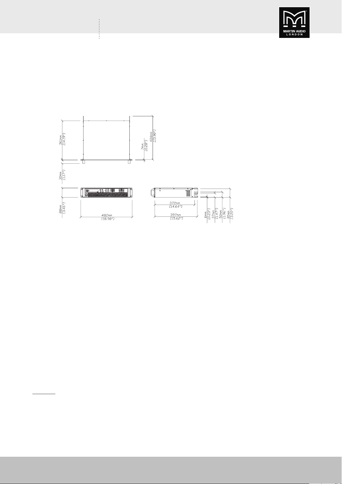
Enclosure Standard 19” 2U (88 mm ) with handles and optional rear support system
Depth (behind rack ears) 357 mm (14”)
Net Weight 12.5 kg (27.5 lbs)
Options
Rear rack support kit IKRACK
34
XE300/XE500 User Guide V1.0
Page 35

XE300/XE500 USER GUIDE
XE SERIES MONITORS - TECHNICAL DRAWINGS
XE300
XE500
XE300/XE500 User Guide V1.0
35
Page 36

XE300/XE500 USER GUIDE
WARRANTY
Martin Audio XE Series Stage Monitors are warranted against manufacturing defects in materials
or craftsmanship over a period of 5 years from the date of original purchase.
During the warranty period Martin Audio will, at its discretion, either repair or replace products
which prove to be defective provided that the product is returned in its original packaging,
shipping prepaid, to an authorised Martin Audio service agent or distributor.
Martin Audio Ltd. cannot be held responsible for defects caused by unauthorised modifications,
improper use, negligence, exposure to inclement weather conditions, act of God or accident, or
any use of this product that is not in accordance with the instructions provided by Martin Audio.
Martin Audio is not liable for consequential damages.
This warranty is exclusive and no other warranty is expressed or implied. This warranty does not
affect your statutory rights.
COPYRIGHT AND TRADEMARKS
Copyright Martin Audio Ltd. Martin Audio and Coaxial Differential Dispersion are registered
trademarks of Martin Audio Ltd and are registered in the United Kingdom, United States and
other countries.
All other trademarks and trade names are the property of their respective owners.
2017 © Martin Audio Limited. All rights reserved.
36
XE300/XE500 User Guide V1.0
Page 37

XE300/XE500 USER GUIDE
XE300/XE500 User Guide V1.0
37
Page 38

Martin Audio Limited
Century Point
Halifax Road
Cressex Business Park
High Wycombe
Buckinghamshire
HP12 3SL
England
UK
Telephone: +44 (0)1494 535312
Facsimile: +44 (0)1494 438669
E-mail: info@martin-audio.com
NORTH AMERICA
Telephone: 519 747 5853
Facsimile: 519 747 3576
E-mail: infona@martin-audio.com
All information is Copyright © 2017 Martin Audio Ltd.
Copyright Martin Audio Ltd. Martin Audio and Coaxial Differential Dispersion are registered trademarks of
Martin Audio Ltd and are registered in the United Kingdom, United States and other countries.
All other trademarks and trade names are the property of their respective owners.
www.martin-audio.com
 Loading...