

Page 1

OmniLine
System Preparation
®
The Martin Experience
All material © 2009. Martin Audio Ltd. Subject to change without notice.
Page 2

Martin Audio Omniline® system preparation
Notes:
A variety of mounting and suspension systems are available. Make sure you
have ordered the required wall mounting or suspension kit to suit your chosen
installation method. See section 4 for kit details…
Martin Audio Omniline® loudspeakers must be installed by experienced
loudspeaker installation personnel using the full installation kit provided
It is the installer’s responsibility to ensure that all relevant local, national and
international electrical, fire and building safety regulations are complied with
Every Omniline® loudspeaker must be fitted with a steel safety wire this can
be fitted between an attachment bracket (provided) and a suitable supporting
structure.
All material © 2009. Martin Audio Ltd. Subject to change without notice.
1
Page 3

You will need the following tools for OmniLine preparation and installation.
Tool Size Operation
Building arrays
Screwdriver PZ1 Rear covers removal/assembly
Allen Key/Socket Set 4 Link Plates assembly
Open Ended Spanner 10mm Link Plates assembly
Screwdriver S3 Wiring
4 Cab Bracket
Allen Key/Socket Set 5 Adding brackets to the array
Allen Key/Socket Set 8 Adding collar
Allen Key/Socket Set 6 Clamping collar
Open Ended Spanner 13mm Clamping collar
8 - 16 Bracket
Allen Key/Socket Set 5 Adding brackets to the array
Allen Key/Socket Set 8 Adding collar
Allen Key/Socket Set 6 Clamping collar
Open Ended Spanner 13mm Clamping collar
Pliers Split pin removal/fitting
Open Ended Spanner 8mm Attaching Dog Grip
Flying Bracket
Allen Key/Socket Set 5 Adding brackets to the array
Allen Key/Socket Set 6 Adding brackets to the array
PZ = Pozidrive S = Straight/Flat head
All material © 2009. Martin Audio Ltd. Subject to change without notice.
2
Page 4

1 Introduction
Omniline® is a versatile, micro-line array designed for installation in a wide variety of
architectural environments.
It’s modular approach and scalability extends its use from foreground applications to
sound reinforcement in large acoustic spaces.
Intelligent software enables an array to be configured to deliver sound precisely over
any vertical angle to fit the venue profile without spilling onto surfaces where sound is
not required.
Additionally, elimination of high frequency side-lobes gives Omniline® the advantage
over currently available DSP steered columns, making it suitable for high quality
music reproduction as well as speech in large, reverberant spaces.
2 Main features
The Omniline® module consists of 2 x 89mm reflex-loaded, mid/low radiators either
side of a central strip of 5 x 14mm HF devices in a unique, patent pending
arrangement. All drives have been painstakingly developed from the ground up,
specifically for the array module.
3 Warranty
Martin Audio Omniline® products are warranted against manufacturing defects in
materials or craftsmanship over a period of 5 years from the date of original
purchase.
During the warranty period Martin Audio will, at its discretion, either repair or replace
products which prove to be defective provided that the product is returned in its
original packaging, shipping prepaid, to an authorised Martin Audio service agent or
distributor.
Martin Audio Ltd. cannot be held responsible for defects caused by unauthorised
modifications, improper use, negligence, exposure to inclement weather conditions,
act of God or accident, or any use of this product that is not in accordance with the
instructions provided by Martin Audio. Martin Audio is not liable for consequential
damages.
This warranty is exclusive and no other warranty is expressed or implied. This
warranty does not affect your statutory rights.
4 Installation methods and kit details
A site survey is required before purchase. Omniline® software should be used to
determine the position, installation method and number of Omniline® modules
required for the installation.
All material © 2009. Martin Audio Ltd. Subject to change without notice.
3
Page 5

Omniline® module pack
Each pack of OmniLine® modules comprises the following parts:
Omniline® module pack
Note that the self adhesive shade included in the module pack may be used to
prevent down-lighting from shining down through the grilles in architecturally
sensitive locations.
There are three methods of installing an Omniline® Loudspeaker system. Choose
the position and number of Omniline® modules required as indicated by the
Omniline® software.
All material © 2009. Martin Audio Ltd. Subject to change without notice.
4
Page 6

4 x OmniLine® wall mounting kit
Each 4 x OmniLine® wall mounting kit comprises the following parts:
4 x OmniLine® wall mounting kit
All material © 2009. Martin Audio Ltd. Subject to change without notice.
5
Page 7

8-16 x OmniLine® wall mounting kit
Each 8-16 x OmniLine® wall mounting kit comprises the following parts:
8-16 x OmniLine® wall mounting kit
All material © 2009. Martin Audio Ltd. Subject to change without notice.
6
Page 8
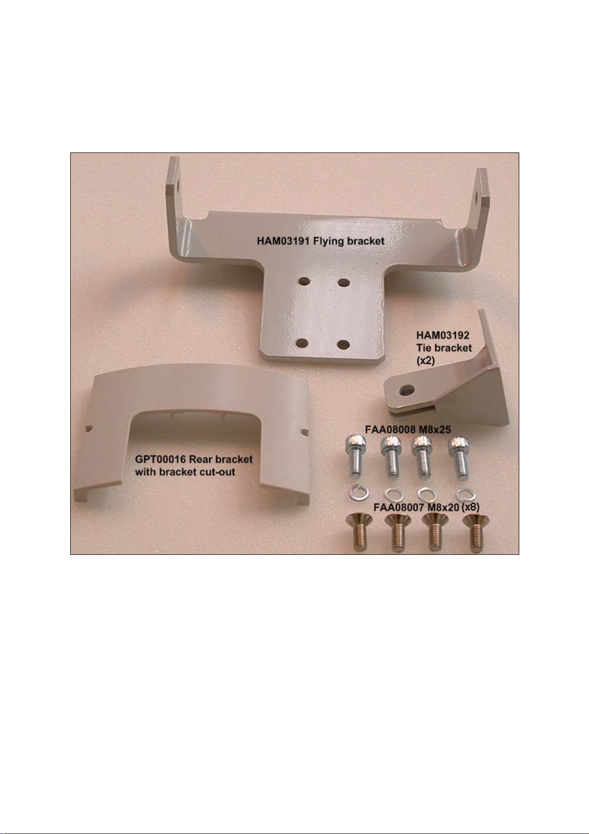
OmniLine® flying kit
Each OmniLine® flying kit comprises the following extra parts.
Please note that the flying kit also includes the ASF20024 wire rope kit (not shown):
5 Unpacking
Every Martin Audio loudspeaker is built to the highest standard and thoroughly
inspected before it leaves the factory.
After unpacking the system, examine it carefully for any signs of transit damage and
inform your dealer if any such damage is found.
We suggest that you retain the original packaging so that the system can be
repacked at a future date if necessary. Please note that Martin Audio and its
distributors cannot accept any responsibility for damage to any returned product
through the use of non-approved packaging.
All material © 2009. Martin Audio Ltd. Subject to change without notice.
7
Page 9

5.1 System preparation
To avoid flattening or damaging your OmniLine grilles, we strongly recommend that
you keep each block of four Omniline® modules in their polystyrene trays.
Take off the rear covers by removing the rear screws from each unit.
Tips!
1) If you are not using a magnetic screwdriver, we recommend covering the
rear port holes with some tape as shown above to prevent dropping screws
down the ports!
All material © 2009. Martin Audio Ltd. Subject to change without notice.
8
Page 10

2) Press the screws into the front of the polystyrene tray to avoid loosing
them.
5.2 Splay angle adjustment
Omniline® modules are shipped with splay angles set at 0 degrees. Having
determined splay angles and mounting or suspension attachment points using the
Omniline® software, set the required inter-module splay angles as follows:
Tip!
Leave modules that require wall mounting or suspension attachments (see software
recommendations) until last as these brackets need to be orientated and fitted before
nearby link pins are inserted – see later…
1) Remove the rear cover
2) Remove the orange safety clip
3) Remove the linking pins from the splay angle holes
All material © 2009. Martin Audio Ltd. Subject to change without notice.
9
Page 11
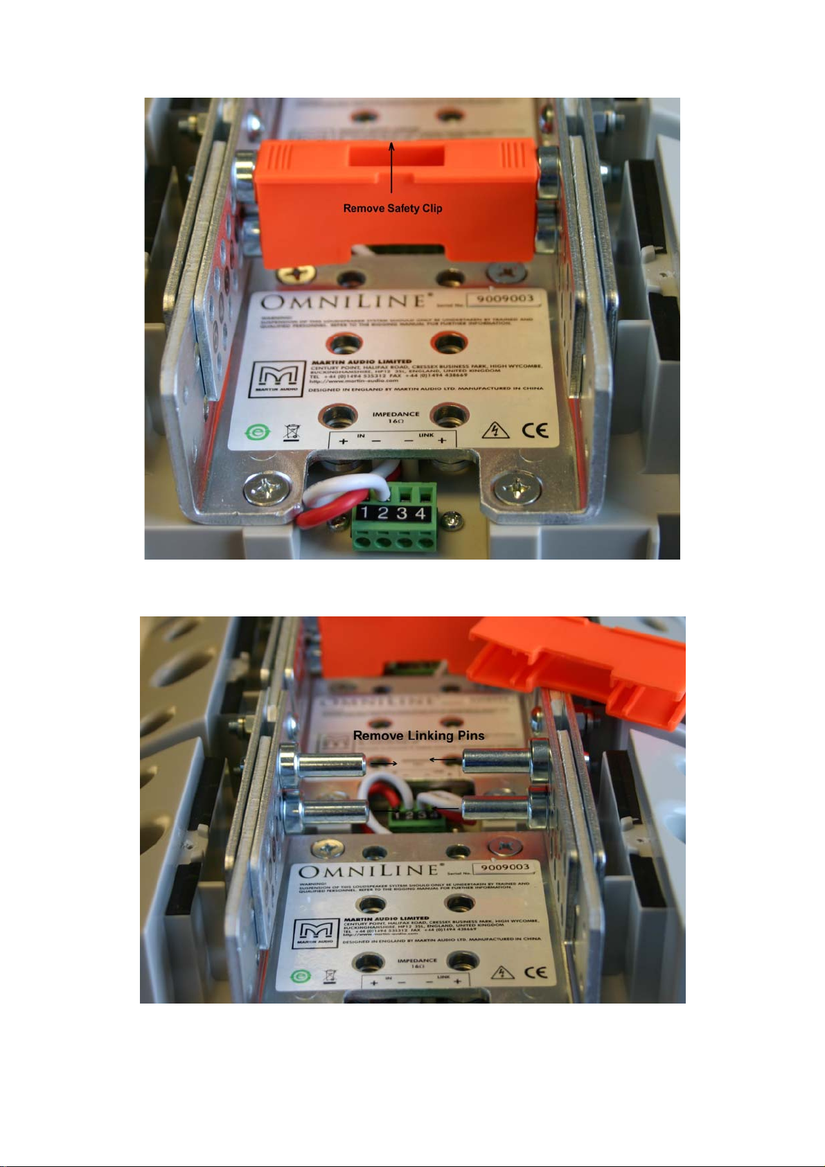
Remove the Orange Safety clip
Remove the link Pins
All material © 2009. Martin Audio Ltd. Subject to change without notice.
10
Page 12
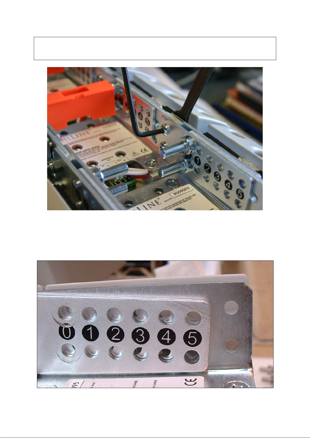
Tip!
If the linking pins are difficult to remove, loosen the four link plate nuts and bolts for
that module. Don’t forget to re-tighten them after you have positioned the link pins
Loosen the Link Plate Nuts and bolts if necessary
4) Angle the Omniline® modules to the required splay angle lining up the link
plate holes at the required angle positions marked on the bracket
Link plates holes lined up for 5deg splay
All material © 2009. Martin Audio Ltd. Subject to change without notice.
11
Page 13
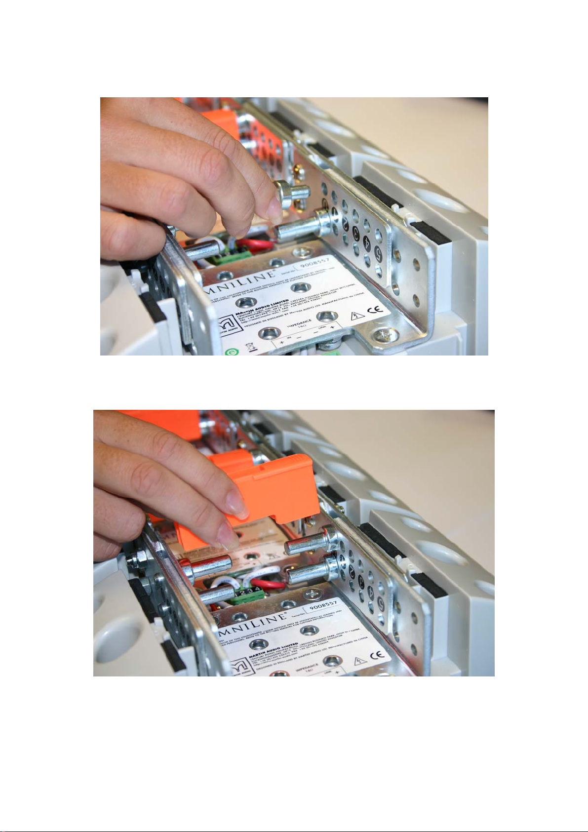
5) Insert the four linking pins into the aligned link plate holes.
6) Replace the orange safety clip after positioning all four linking pins…
Replace the orange safety clips!
System wiring
See separate document entitled Powering your Omniline®.
All material © 2009. Martin Audio Ltd. Subject to change without notice.
12
Page 14

4-Omniline® module wall mounting
To remind you:
Martin Audio Omniline® loudspeakers must be installed by experienced
loudspeaker installation personnel using the full installation kit provided
It is the installer’s responsibility to ensure that all relevant local, national and
international electrical, fire and building safety regulations are complied with
Every Omniline® loudspeaker must be fitted with a steel safety wire this can
be fitted between an attachment bracket (provided) and a suitable supporting
structure.
6.1
Fit the U-bracket first – and then the linking pins.
Note that the recommended U-bracket position is on the second OmniLine unit from
the bottom of the arrays.
Its final orientation will be determined by the required linking pin positions – one way
round for 0-2 degrees, the other way round for 3-5 degrees.
U-bracket (shown positioned for 4 degree linking pin position)
All material © 2009. Martin Audio Ltd. Subject to change without notice.
13
Page 15
6.2
If you haven’t already prepared Omniline® module splay angles as indicated by the
Omniline® software – see section 5.2 above…
6.3
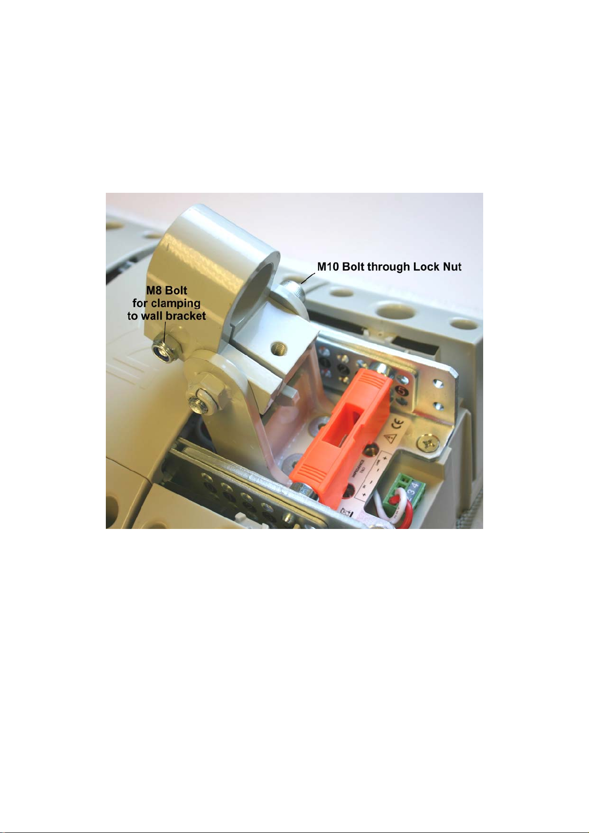
Fit the Collar to the U-bracket using the FAA10004 M10 x 75 bolt. Note the
orientation – collar towards the top of the array (left on the photograph)
1) Tighten the M10 bolt – tight enough so that it protrudes at least 1.5 thread
turns through the lock nut but still allows U-bracket movement for easy
adjustment.
2) Fit the FAA08005 M8 x 60mm bolt (see kit identification pictures earlier)
loosely to the collar as shown above
6.4
Wire up the array.
See separate document entitled Powering your Omniline®.
All material © 2009. Martin Audio Ltd. Subject to change without notice.
14
Page 16

6.5
Fit rear the rear covers - using the cut out version for the module with the bracket
6.6
1) Fit the HAM02012 Wall Bracket – see kit identification picture earlier. A drilling
template is included with the bracket
Lift the block of four Omniline® modules onto the wall mounting – see below.
2) Fit the FAA08004 M8 x 40 bolt and adjust screw to set vertical tilt angle
3) Tighten clamping bolt (FAA08005 M8 x 60) after setting the horizontal angle
4) Check that the M10 x 75 collar-to-U-bracket bolt is firmly screwed into its
locking nut
Recheck everything!
ALLWAYS double check that all Orange safety clips are in place as this is essential to
ensure that the array will stay safely locked together
All material © 2009. Martin Audio Ltd. Subject to change without notice.
15
Page 17

6 8-16 Omniline® module wall mounting
To remind you:
Martin Audio Omniline® loudspeakers must be installed by experienced
loudspeaker installation personnel using the full installation kit provided
It is the installer’s responsibility to ensure that all relevant local, national and
international electrical, fire and building safety regulations are complied with
Every Omniline® loudspeaker must be fitted with a steel safety wire this can
be fitted between an attachment bracket (provided) and a suitable supporting
structure.
7.1
1) Prepare your blocks of four OmniLine® modules to the splay angles
recommended by the OmniLine® software – see section 5.2 earlier.
2) Add link plates to the lower module of the upper 4-module blocks using the
link plate bolts and lock nuts supplied with each four OmniLine® modules –
see kit picture at the beginning of this document.
Fit link plates (supplied with each four modules)
to the bottom of each block of four
3) Fit 4-module blocks together by interlocking modules together near the front.
All material © 2009. Martin Audio Ltd. Subject to change without notice.
16
Page 18
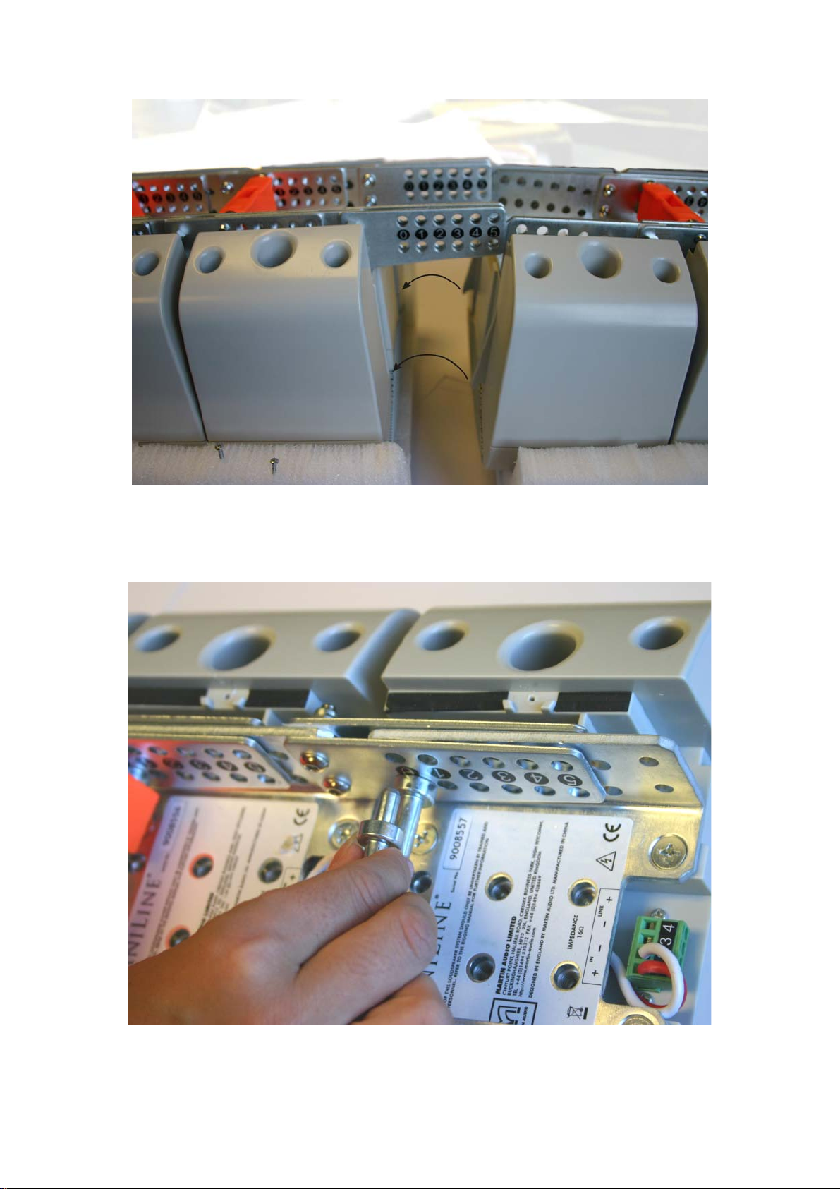
Interlock modules together
Ensure that the tongues (right) are properly locked into the grooves (left) – see
arrows in above illustration…
Adding the linking pins
4) Add the linking pins as shown in section 5.2 earlier.
All material © 2009. Martin Audio Ltd. Subject to change without notice.
17
Page 19

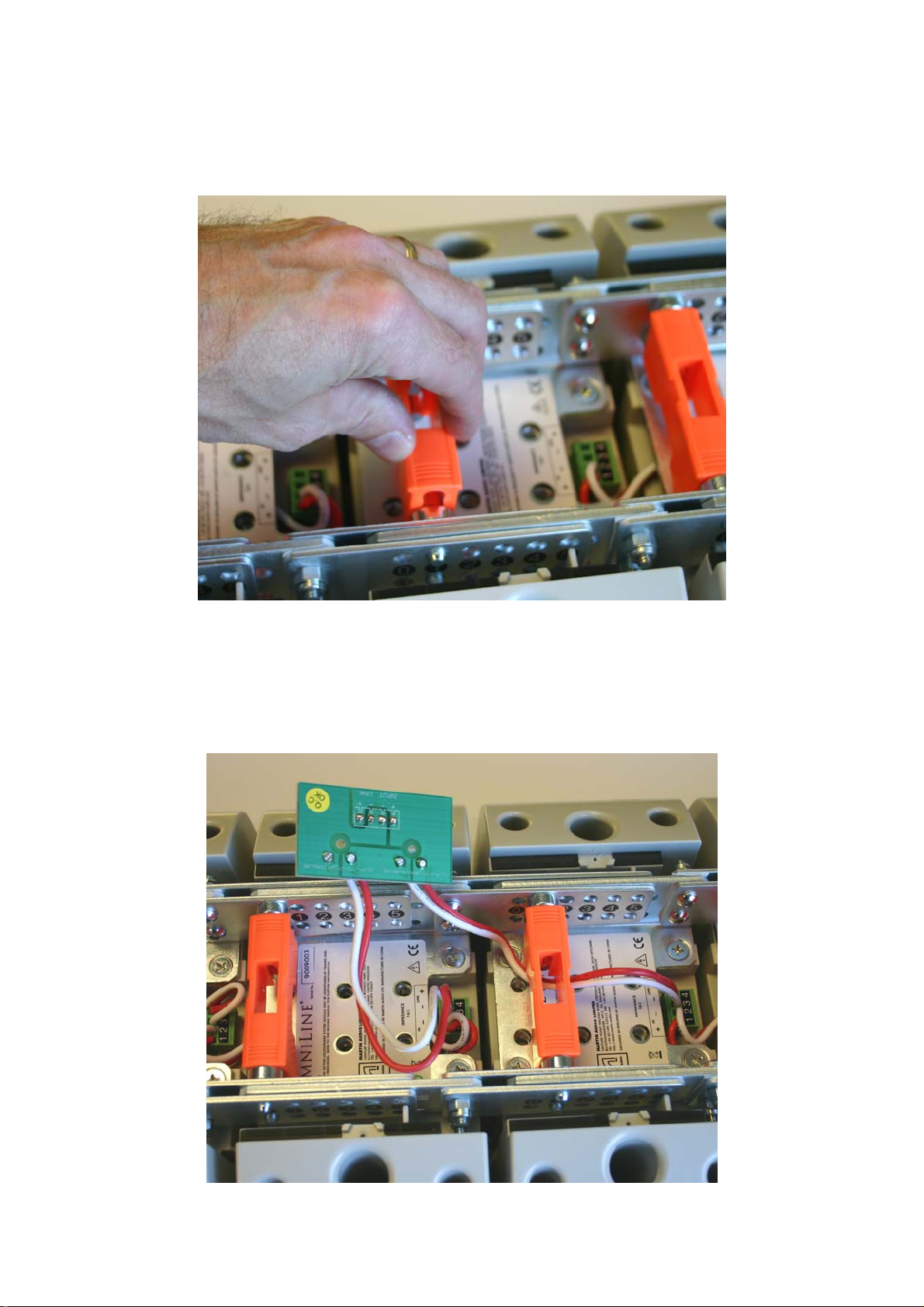
5) Remember to add the safety clips!
6) Wire the 4-module blocks together into bigger blocks of 8 or 12 modules*
using the connector pcb supplied with each block of four OmniLine® modules.
* See separate document entitled Powering your Omniline® for further
details.
Notes:
White = -ve and Orange = +ve
Upper and lower block connections are marked on the pcb.
Route the wires between the linking pins to avoid crushing them when
the rear covers are replaced.
All material © 2009. Martin Audio Ltd. Subject to change without notice.
18
Page 20

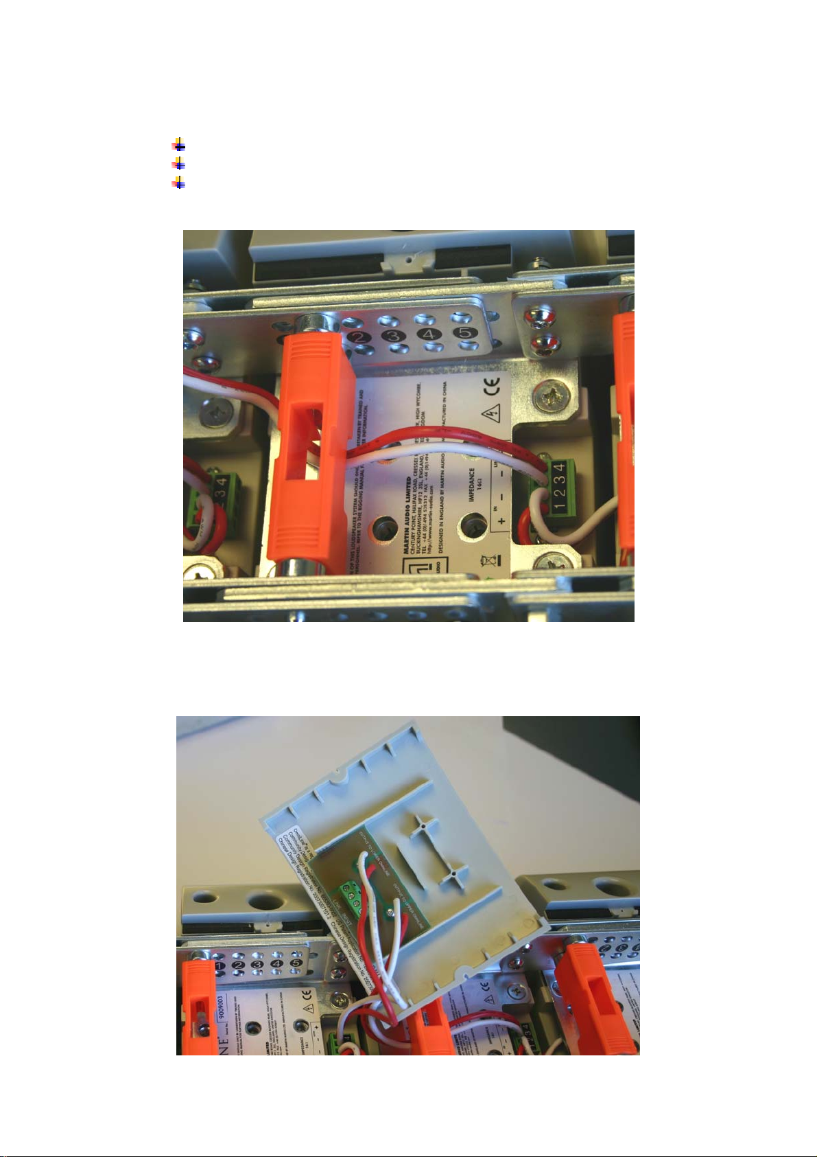
7) Screw the pcb to the inside of the most convenient rear cover using the self
tap screws provided with each set of four modules. Its orientation will depend
on that module’s linking pin positions.
7.2
Fit the U-bracket to the lower OmniLine® module first – and then the linking pins.
Final U-bracket positioning will be determined by the required linking pin positions –
one position for 0-2 degrees and the other position for 3-5 degrees. See illustration
below…
All material © 2009. Martin Audio Ltd. Subject to change without notice.
19
Page 21

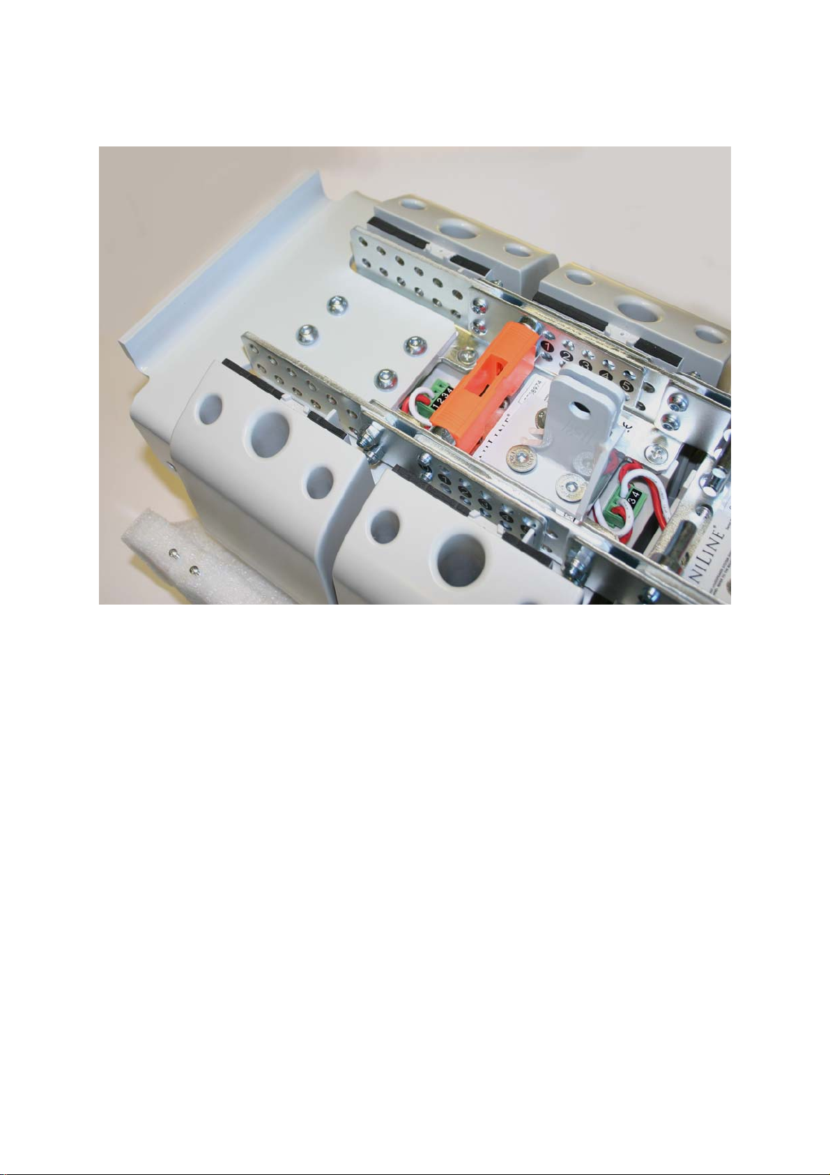
Once you have fitted the U-bracket, angle the lower module to the required setting,
ensuring the holes line up, then replace all four linking pins and the safety clip – see
section 5.2 earlier.
U-bracket positioned for 5 deg lower module angle
7.3
Fit a main HAM03192 tie-bracket to the Omniline® module indicated by the
Omniline® software.
All material © 2009. Martin Audio Ltd. Subject to change without notice.
20
Page 22

Again, the bracket position and orientation will be determined by the angle setting
required for that Omniline® module.
Remove the linking pins if necessary and fit the bracket in the correct orientation.
Angle the Omniline® module and replace the linking pins at the required angle.
7.4
Fit the second HAM03192 tie-bracket, to the top Omniline® module.
7.5
Refit the lids
7.6
Fit the Collar to the U-bracket using the M10 x 65 Cap Head Machine Screw, in the
orientation shown below.
Tip!
Leave the U-bracket screw (right above) and clamping screw (left above) finger tight
until the system is mounted onto the wall bracket – remembering to tighten them fully
at that stage.
All material © 2009. Martin Audio Ltd. Subject to change without notice.
21
Page 23

7.7
After removing the pin and R-clip from the DIN15315 wedge fastener, load the
ASF20024 wire rope as follows:
Place a loose loop of ASF20024 wire rope into the wedge socket
Loop the wire round the wedge and pull it semi-tight
Attach the Wire Rope assembly to the main tie bracket using the pin and R-clip. Note
the R-clip washer.
Roughly adjust the length of the wire using the wedge socket.
All material © 2009. Martin Audio Ltd. Subject to change without notice.
22
Page 24
7.8
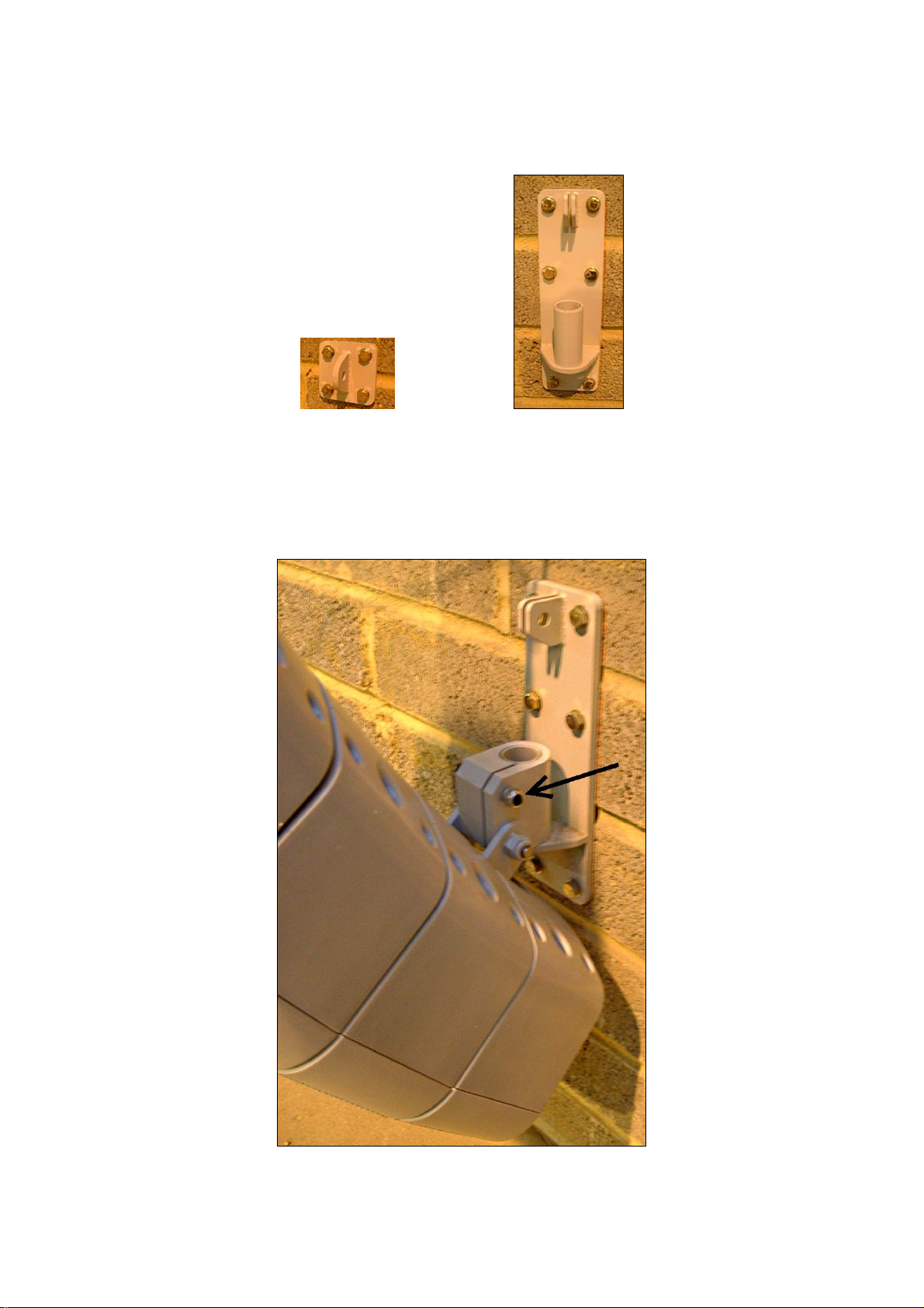
Fit the top HAM02027 and bottom HAM02026 wall brackets onto the wall using the
drilling templates included with the brackets.
HAM02027 HAM02026
The Omniline® software will indicate the recommended heights of these brackets.
7.9
Lift the array and slot it down onto the bottom bracket
Tighten the clamp screw (arrowed).
All material © 2009. Martin Audio Ltd. Subject to change without notice.
23
Page 25

7.10
Shackle the end of the wire rope to the top wall bracket.
7.11
Use the wedge socket to fine tune the down tilt of the array. Once the angle is set,
add the DIN1142 rope grip for extra security and make sure everything is tight.
Trim the wire rope if required.
7.12
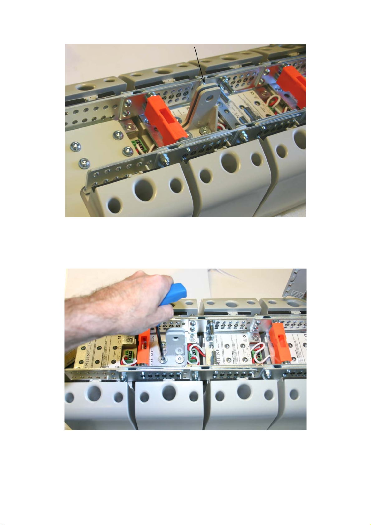
Tighten the U-bracket-to-sleeve screw (arrowed)
Add a safety wire rope between the second (top) tie-bracket and an approved,
secure part of the building structure.
Recheck everything!
ALLWAYS double check that all Orange safety clips are in place as this is essential to
ensure that the array will stay safely locked together
All material © 2009. Martin Audio Ltd. Subject to change without notice.
24
Page 26

8 Omniline® flying system
To remind you:
Martin Audio Omniline® loudspeakers must be installed by experienced
loudspeaker installation personnel using the full installation kit provided
It is the installer’s responsibility to ensure that all relevant local, national and
international electrical, fire and building safety regulations are complied with
Every Omniline® loudspeaker must be fitted with an additional steel safety
wire this can be fitted between the HAM03192 tie bracket and an approved
supporting structure.
8.1
1) Prepare your 4-module blocks to the splay angles recommended by the
OmniLine® software – see section 5.2 earlier.
2) Add link plates to the lower module of the upper 4-module blocks using the
link plate bolts and lock nuts supplied with each four OmniLine® modules –
see kit picture at the beginning of this document.
Fit link plates (supplied with each four modules)
to the bottom of each block of four
All material © 2009. Martin Audio Ltd. Subject to change without notice.
25
Page 27

3) Fit 4-module blocks together by interlocking modules together near the front.
Interlock modules together
Ensure that the tongues (right) are properly locked into the grooves (left) – see
arrows in above illustration…
Adding the linking pins
All material © 2009. Martin Audio Ltd. Subject to change without notice.
26
Page 28
4) Add the linking pins as shown in section 5.2 earlier.
5) Remember to add the safety clips!
6) Wire the 4-module blocks together into bigger blocks of 8 or 12 modules*
using the connector pcb supplied with each block of four OmniLine® modules.
* See separate document entitled Powering your Omniline® for further
details.
All material © 2009. Martin Audio Ltd. Subject to change without notice.
27
Page 29
Notes:
White = -ve and Orange = +ve
Upper and lower block connections are marked on the pcb.
Route the wires between the linking pins to avoid crushing them when
the rear covers are replaced.
7) Screw the pcb to the inside of the most convenient rear cover using the self
tap screws provided with each set of four modules. Its orientation will depend
on that module’s linking pin positions.
All material © 2009. Martin Audio Ltd. Subject to change without notice.
28
Page 30
8.2
Fit the HAM03191 flying bracket (arrowed) to the top Omniline® module of the array.
HAM03191 flying bracket in place
8.3
Fit one of the HAM03192 tie brackets to the second module from the top of the array
to form a safety point.
The position and orientation of the bracket will be determined by the angle setting of
the Omniline® module to which it is fitted. Attach the bracket – temporarily removing
the linking pins if necessary.
All material © 2009. Martin Audio Ltd. Subject to change without notice.
29
Page 31
HAM03192 tie bracket in place
8.4
Fit the second HAM03192 tie-bracket to the Omniline® module indicated by the
Omniline® software.
Again, the bracket position and orientation will be determined by the angle setting
required for that Omniline® module.
All material © 2009. Martin Audio Ltd. Subject to change without notice.
30
Page 32

Remove the linking pins if necessary and fit the bracket in the correct orientation.
Angle the Omniline® module and replace the linking pins at the required angle.
8.5
Refit the rear covers
8.6
Employ a professional rigger to rig the system from the HAM03191 flying bracket at
the front and the lower HAM03192 tie brackets at the rear.
8.7
Add an extra safety wire rope between the top tie-bracket and an approved, secure
part of the building structure.
Recheck everything!
If you are inexperienced, or in any doubt at all, get an independent safety check.
ALLWAYS double check that all Orange safety clips are in place as this is essential to
ensure that the array will stay safely locked together
All material © 2009. Martin Audio Ltd. Subject to change without notice.
31
Page 33

9. Omniline Bottom Cover
The Omniline Bottom Cover Plate
An Omniline array can be finished off with the addition of the optional Bottom Cover
which fits to the base of the lowest OmniLine module in the array to give a very neat
finish. This may not be necessary for wall mounted arrays but is often essential for
flown arrays where the bottom of the array is often visible.
Bottom Cover mounting detail
The bottom cover is fitted via the raised mounting bracket on the inside of the cover
which lines up with the holes on the Omniline bracket which are normally used to
attach the linking plates. It uses the same nuts and bolts as the linking plates, you will
All material © 2009. Martin Audio Ltd. Subject to change without notice.
32
Page 34

always have a set of these left over as each block of four Omniline Starter Kits has a
set to connect to the modules underneath it. Obviously the bottom modules have
nothing connected to them!
9.1
You will need the back cover of the lowest Omniline module removed ready to fit the
cover
Tip!
Remove the covers and the orange safety clips from the bottom two modules as this
will make it much easier to fit the Allen key into the bolts to tighten them up
All material © 2009. Martin Audio Ltd. Subject to change without notice.
33
Page 35

9.2
Position the bottom cover in place under the lowest module. You will find that the
mounting bracket will fit snugly between the Omniline steel brackets and the holes
will line up with the linking plate holes. Fit the spare linking plate nuts and bolts
starting with the lowest two and tighten with a 4mm Allen Key and a 10mm open
ended spanner
Tighten the fixing nuts and bolts
All material © 2009. Martin Audio Ltd. Subject to change without notice.
34
Page 36
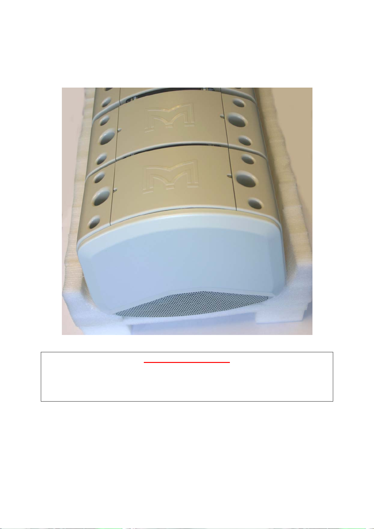
9.3
REPLACE ANY SAFETY CLIPS THAT YOU REMOVED!, then replace the backs of
the modules. The system is now ready to be flown.
System ready for flying with bottom cover fitted
Recheck everything!
If you are inexperienced, or in any doubt at all, get an independent safety check.
ALLWAYS double check that all Orange safety clips are in place as this is essential to
ensure that the array will stay safely locked together
All material © 2009. Martin Audio Ltd. Subject to change without notice.
35
 Loading...