

Page 1
VC-Feeder™
User Manual
Page 2
Dimensions
Variant with M16 connectors illustrated
36
68
180 (approx.)
164
180 (approx.)
180 (approx.)
All dimensions are in millimeters
Information subject to change without notice. HARMAN Professional Denmark ApS disclaims
liability for any injury, damage, direct or indirect loss, consequential or economic loss or any other
loss occasioned by the use of, inability to use or reliance on the information contained in this
document.
©2012-2018 HARMAN Professional Denmark ApS. All rights reserved. Martin® is a registered
trademark of HARMAN Professional Denmark ApS registered in the United States and/or other
countries. Features, specifications, and appearance are subject to change without notice.
HARMAN Professional Denmark ApS – Olof Palmes Alle 18 – 8200 Aarhus N – Denmark
www.martin.com
VC-Feeder User Manual – P/N 35000262, Rev. D
Page 3

Contents
Dimensions . . . . . . . . . . . . . . . . . . . . . . . . . . . . . . . . . . . . . . . . . . . . . . . . . .2
Safety information . . . . . . . . . . . . . . . . . . . . . . . . . . . . . . . . . . . . . . . . . . . . .4
Introduction . . . . . . . . . . . . . . . . . . . . . . . . . . . . . . . . . . . . . . . . . . . . . . . . . .7
Overview . . . . . . . . . . . . . . . . . . . . . . . . . . . . . . . . . . . . . . . . . . . . . . . . . . . . .9
Physical installation . . . . . . . . . . . . . . . . . . . . . . . . . . . . . . . . . . . . . . . . . . 10
Fastening to a surface . . . . . . . . . . . . . . . . . . . . . . . . . . . . . . . . . . . . . . .10
Clamping to a truss . . . . . . . . . . . . . . . . . . . . . . . . . . . . . . . . . . . . . . . . . 11
Connections . . . . . . . . . . . . . . . . . . . . . . . . . . . . . . . . . . . . . . . . . . . . . . . . .12
Input connections: general . . . . . . . . . . . . . . . . . . . . . . . . . . . . . . . . . . . .13
P3 video installations . . . . . . . . . . . . . . . . . . . . . . . . . . . . . . . . . . . . . . . .14
DMX-controlled installations . . . . . . . . . . . . . . . . . . . . . . . . . . . . . . . . . . .15
Throughput connections . . . . . . . . . . . . . . . . . . . . . . . . . . . . . . . . . . . . . .17
Output connections . . . . . . . . . . . . . . . . . . . . . . . . . . . . . . . . . . . . . . . . .19
Setup . . . . . . . . . . . . . . . . . . . . . . . . . . . . . . . . . . . . . . . . . . . . . . . . . . . . . . .20
Setting up for P3 video display . . . . . . . . . . . . . . . . . . . . . . . . . . . . . . . . .20
Setting up for DMX control . . . . . . . . . . . . . . . . . . . . . . . . . . . . . . . . . . . .20
Operation . . . . . . . . . . . . . . . . . . . . . . . . . . . . . . . . . . . . . . . . . . . . . . . . . . .21
Ambient temperatures . . . . . . . . . . . . . . . . . . . . . . . . . . . . . . . . . . . . . . .21
P3 video display . . . . . . . . . . . . . . . . . . . . . . . . . . . . . . . . . . . . . . . . . . . .21
DMX control . . . . . . . . . . . . . . . . . . . . . . . . . . . . . . . . . . . . . . . . . . . . . . . 21
Monitoring, testing and resetting the installation . . . . . . . . . . . . . . . . . . . 22
Service . . . . . . . . . . . . . . . . . . . . . . . . . . . . . . . . . . . . . . . . . . . . . . . . . . . . .24
Cleaning . . . . . . . . . . . . . . . . . . . . . . . . . . . . . . . . . . . . . . . . . . . . . . . . . .24
Software installation . . . . . . . . . . . . . . . . . . . . . . . . . . . . . . . . . . . . . . . . . 24
Troubleshooting . . . . . . . . . . . . . . . . . . . . . . . . . . . . . . . . . . . . . . . . . . . . .25
Specifications . . . . . . . . . . . . . . . . . . . . . . . . . . . . . . . . . . . . . . . . . . . . . . .26
Page 4
Safety information
The following symbols are used to identify important safety information in
this guide:
Warning!
Safety hazard.
Risk of personal
injury.
Warning!
Fire hazard.
Warning!
Hazardous
voltage. Risk of
severe or lethal
electric shock.
Warning!
Refer to user
documentation.
Warning! Read this user manual before installing and operating the
VC-Feeder.
Warning! The VC-Feeder is designed to integrate with other Martin®
devices in a video display installation. Follow the safety precautions
given not only in this user manual but also in the manuals of all the
devices you connect to it. Observe all warnings given in the manuals
and printed on devices. Install and operate devices only as described
in the manuals and only in accordance with local laws and
regulations. Keep this manual for future reference. Manuals are
supplied with devices and also available for download from
www.martin.com.
Warning! The VC-Feeder is not for household use. It presents risks
of severe injury or death due to fire and burn hazards, electric shock
and falls. It must be installed by qualified technicians only.
Warning! There are no user-serviceable parts inside the VC-Feeder.
Refer any operation not described in this manual to Martin® or its
authorized service agents.
If you have any questions about how to operate the VC-Feeder safely,
please contact your Martin® supplier or call the Martin® 24-hour service
hotline on +45 8740 0000, or in the USA on 1-888-tech-180.
4 Martin® VC-Feeder user manual
Page 5

PROTECTION FROM ELECTRIC SHOCK
• Follow carefully the directions given in the user manuals of all the
devices that you intend to connect to the VC-Feeder, particularly the
instructions, warnings and limits that apply to:
- system layout,
- connections to other devices,
- specified cables,
- maximum cable lengths, and
- maximum number of devices that can be connected.
• The VC-Feeder accepts input power at 48 VDC nominal via its
combined power/data input connector marked IN. Do not supply it with
power at any other voltage.
• The VC-Feeder can relay power at 48 VDC nominal via its throughput
connector marked THRU. Connect only devices that accept 48 VDC to
the THRU connector.
• The VC-Feeder can supply power at 15 VDC nominal via its combined
power/data output connector marked OUT. Connect only devices that
accept 15 VDC to the THRU connector.
• A linked chain that consists of one or more VC-Feeder devices plus
display devices can draw a safe maximum total current of 7.5 A. Do not
create an interconnected chain of devices with a total combined current
draw that exceeds this 7.5 A limit. If the total current draw of a chain of
devices has reached 7.5 A and you need to supply power to more
devices, you must begin a new chain.
• If using a 48 VDC external PSU (power supply unit) in a DMX-controlled
system, do not create an interconnected chain of devices with a total
combined current draw that exceeds 7.5 A or the maximum current
draw rating for the PSU output, whichever is lower. If the total current
draw of a chain of devices has reached 7.5 A (or the maximum current
rating for the PSU output, if this is lower than 7.5 A) and you need to
supply power to more devices, you must begin a new chain that is
connected to a new PSU output.
• Provide a means of locking out power that allows power to the
installation to be shut down and made impossible to reapply, even
accidentally, during work on the installation.
• Shut down power to the installation during service and when it is not in
use.
• Use only the cables specified by Martin® for the devices concerned to
interconnect them. If the specified cables are not long enough for an
intended cable run, consult Martin® for assistance in finding or creating
a safe alternative cable.
• Before applying power to the installation, check that all power
distribution equipment and cables are in perfect condition, rated for the
Safety information 5
Page 6
current requirements of all connected devices and of suitable type for
the location (including water, pollution, temperature and UV resistance).
• Isolate the installation from power immediately if any device, cable or
power plug is in any way damaged or defective, or if there are any signs
of overheating. Do not reapply power until the fault has been rectified.
• Do not operate the installation if any cover or component is missing,
damaged or deformed.
• The VC-Feeder is IP65-rated and resists the ingress of water, but do not
immerse it, install it in a location where flooding may occur or expose it
to high-pressure water jets.
PROTECTION FROM BURNS AND FIRE
• Provide free airflow and a minimum clearance of 10 cm (4 in.) around
the VC-Feeder.
• Do not operate the VC-Feeder if the ambient temperature (T
) exceeds
a
55° C (131° F).
• Do not modify the VC-Feeder in any way not described in this manual or
install other than genuine Martin® parts. Use only accessories approved
by Martin®.
PROTECTION FROM INJURY
• When installing the VC-Feeder above ground level, ensure that the
primary installation hardware and supporting structure can hold at least
10 times the weight of all the devices they support.
• When suspending the VC-Feeder from a rigging structure, use a rigging
clamp that is approved by an official notified body for the weight it
supports and installed as described in this manual.
• In an overhead installation or where the VC-Feeder may cause injury if it
falls:
- block access below the work area and work from a stable platform
whenever installing, servicing or moving the VC-Feeder,
- install as described in this manual a secondary attachment (such as a
safety wire) that is approved in accordance with UL1573 Section 9.2
and EN 60598-2-17 Section 17.6.6 as a safety attachment for the
weight it must secure if the primary attachment fails, and
- as soon as work is completed, check that all hardware and
components are securely in place and that all installation and rigging
hardware used is securely fastened.
6 Martin® VC-Feeder user manual
Page 7
Introduction
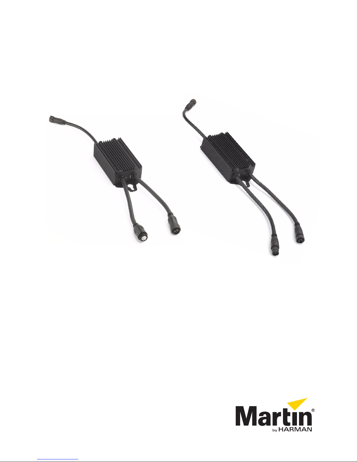
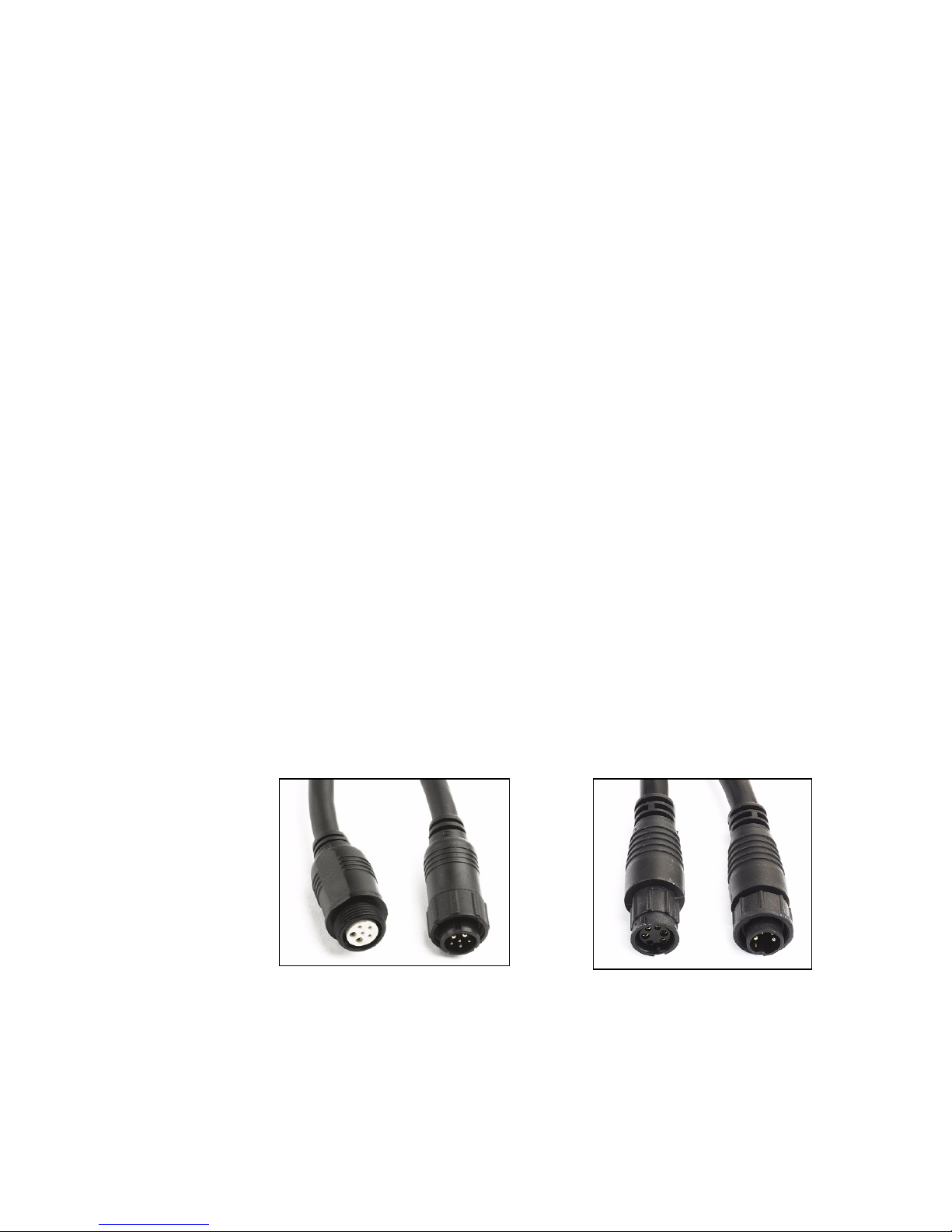
Figure 1:Power and data IN and THRU connector types
M16 connectors BBD connectors
Thank you for selecting the VC-Feeder from Martin® Professional. The
VC-Feeder is a multi-protocol IP65-rated driver box that accepts 48 VDC
power and video/control data, and then supplies 15 VDC power and
video/control data to Martin® LED-based video display products.
For possible system layouts when using the VC-Feeder with Martin®
video display products, see the user documentation for those products.
Martin® user documentation is supplied with products and available for
download from the Martin® website at http://www.martin.com, where you
can also find the latest specifications, firmware updates and support
information for all Martin® products.
Martin® welcomes input from users. Comments or suggestions regarding
this user manual can be e-mailed to service@martin.dk.
Connector types
See Figure 1. The VC-Feeder is available in two models that have
different connector types on their power & data IN and power & data
THRU cable tails:
• VC-Feeder with M16 connectors, featuring the original M16 connectors
for power & data IN and power & data THRU that have been fitted since
the VC-Feeder was launched.
• VC-Feeder with BBD connectors, available from mid-2018, featuring the
same BBD connectors as the Martin® Exterior PixLine, Exterior Dot-HP,
VDO Sceptron, VDO Dotron & VDO Fatron, for power & data IN and
power & data THRU.
M16 and BBD connectors can be interconnected, if necessary, using
adapter cables available from Martin®.
Introduction 7
Page 8

For easy compatibility with existing Martin® VC family products, we
recommend that you use the VC-Feeder with M16 connectors in existing
installations. For easy compatibility with a wider range of Martin video and
lighting products, we recommend that you use the VC-Feeder with BBD
connectors in new installations.
The type of connectors used by Martin® products are listed in their
product specifications on the Martin website at www.martin.com.
The line drawings in this user manual show M16 connectors. BBD
connectors have a slightly different appearance, but their use and function
is identical with M16 connectors.
8 Martin® VC-Feeder user manual
Page 9
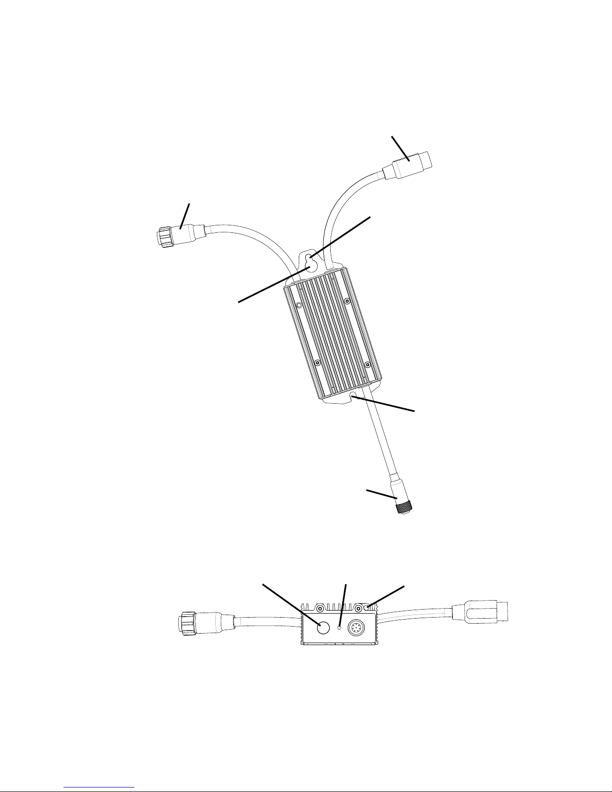
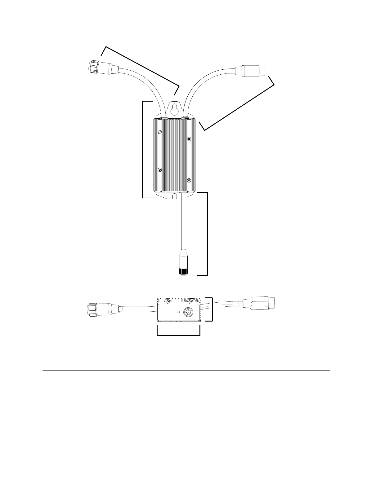
Figure 2: Product overview
Hybrid (15 VDC & data)
output OUT connector
Power (48 VDC) & data)
THRU connector
Power (48 VDC) & data)
IN connector
Rigging clamp
attachment point
Surface mount
attachment point
Surface mount
attachment point
Test/reset button Status LED
Safety wire
attachment point
M16 connector
illustrated
M16 connector
illustrated
Overview
Overview 9
Page 10

Physical installation
Warning! If suspending the VC-Feeder above ground level, secure it
against failure of primary attachments with a safety wire that is
approved as a safety attachment for the weight of the product.
The VC-Feeder can be installed on a flat surface or suspended from a
rigging truss in any orientation. Allow free airflow and at least 10 cm (4 in.)
of clearance around the device.
Supporting surfaces, fasteners and hardware must be capable of
supporting ten times the load they will bear when devices are installed.
Fastening to a surface
The VC-Feeder can be mounted on a flat, stable surface in any orientation
using bolts or screws fastened through the surface mount attachment
points (see Figure 2 on page 9).
To fasten to a surface:
1. Check that the surface is flat and stable, and that the surface and all
installation fasteners can support at least ten times the weight of all
devices and hardware they will bear.
2. Fasten two grade 8.8 minimum steel 6 mm fasteners that are suitable
for the mounting surface and environment through the two slotted
holes that provide the surface mounting points for the VC-Feeder,
ensuring that the fastener heads are wider than the slotted holes.
3. Check that the VC-Feeder is held securely and cannot fall.
4. If the product can cause injury or damage if the fasteners fail, install a
safety wire that is approved as a safety attachment for the weight of
the product by attaching it to the safety wire attachment point (see
Figure 2 on page 9) and a secure anchoring point so that the safety
attachment will catch the product if the primary attachment fails.
5. Check that the product is securely and safely installed.
10 Martin® VC-Feeder user manual
Page 11

Clamping to a truss
Figure 3: Martin® half-
coupler rigging clamp
1. Obtain a rigging clamp and check that
it is undamaged and approved for the
weight it will support. Check that the
structure that will be used for
suspension can bear at least 10 times
the weight of all installed products,
clamps, cables, auxiliary equipment,
etc.
2. Bolt the clamp securely through the
rigging clamp attachment point (see
see Figure 2 on page 9) with a
minimum grade 8.8 steel M12 bolt and
lock nut.
3. Block access under the work area. Working from a stable platform,
fasten the product to the truss with the rigging clamp.
4. Install a safety wire that is approved as a safety attachment for the
weight of the product by attaching it to the safety wire attachment point
(see Figure 2 on page 9) and a secure anchoring point so that the
safety attachment will catch the product if the primary attachment fails.
5. Check that the product is securely and safely installed.
Physical installation 11
Page 12

Connections
Figure 4: VC-Feeder™ connections overview
48 VDC power + data
15 VDC power + data output (OUT) to display devices
throughput (THRU) to
48 VDC power + data
input (IN) from power
and data source other VC-Feeders
Maximum total
current 7.5 A
or maximum
PSU output
current, whichever
is lower
M16 connectors illustrated
Warning! Check that the installation is isolated from AC mains power
and that power cannot be reapplied during work on cables and
connections.
Warning! Before connecting devices to the output (OUT) or
throughput (THRU) connectors of a VC-Feeder, check carefully the
information about system layouts and maximum safe limits:
• in “Safety information” on page 4 of this manual, and
• in the user manuals of the devices in the system.
Warning! When linking a VC-Feeder to other devices using its
throughput connector, respect the maximum limits given in display
device user manuals for the number of devices that can be linked in a
chain and maximum permitted cable lengths.
Important! Do not connect more than twenty (20) VC-Feeder devices
in one linked chain, even if you have not reached the maximum
permitted current draw for the chain.
Figure 4 gives an example of how the VC-Feeder is connected:
12 Martin® VC-Feeder user manual
Page 13

Input connections: general
The VC-Feeder accepts 48 VDC power and data from a P3 video or
DMX/RDM lighting data source via a 180 mm (7 in.) data IN cable tail. The
cable tail has either an M16 or BBD type 6-pin male connector depending
on VC-Feeder model.
The cables required for VC-Feeder connections depend on whether the
installation is intended to display a P3™ video signal or DMX-controlled
lighting effects. These two different setups are covered in separate
sections in this chapter.
Connectors
The VC-Feeder uses custom IP65-rated connectors. Depending on VCFeeder model, either M16 or BBD connectors are fitted to power & data IN
and power & data THRU cable tails (see “Connector types” on page 7).
To ensure that connectors are correctly sealed and avoid damage,
connect them as follows:
1. Line up the raised lug and corresponding groove on the connectors.
The connector pins and holes should now also be lined up.
2. Push the connectors together firmly but without excessive force. If
force seems necessary, separate the connectors and check that they
are correctly lined up, then try again.
3. When the connectors are correctly pushed together:
• on M16 connectors, screw the locking ring on the male connector
onto the thread on the female connector until fully tight
• on BBD connectors, screw the locking ring on the male connector a
quarter turn onto the female connector to lock it.
Extension cables
If the VC-Feeder is not close to the power and data source, you will need
to extend the input cable. To do this, insert a Martin® hybrid extension
cable with either M16 or BBD connectors (depending on VC-Feeder
model) between the input cable shown in Figure 5 and the VC-Feeder’s IN
connector. Suitable extension cables for M16 and BBD connectors are
listed under ”Accessories” on page 27.
Do not exceed the maximum lengths for cable runs specified in display
device user manuals.
Connections 13
Page 14

P3 video installations
Figure 5: Hybrid P3 Input Cable
Cable with 4-pin male XLR to female M16: P/N 11840165
Cable with 4-pin male XLR to female BBD: P/N 91616046
4-pin male XLR VC-Feeder connector
(M16 connector illustrated)
DC power and
video data
to VC-Feeder IN
From DC power and
video data source
In a Martin® P3 video display system, you supply a chain of VC-Feeders
with video data from a P3 video processor via a combined P3 video and
48 VDC power supply device such as a Martin® P3 PowerPort.
Input cable
To connect a chain of VC-Feeders to a DC power and P3 video data
source, you must use a Martin® P3 Hybrid Input Cable shown in Figure 5.
Hybrid P3 Input Cables have:
• a 4-pin male XLR connector that accepts DC power and P3 video data,
and
• a 6-pin female M16 or BBD connector that connects to the VC-Feeder’s
IN connector.
To connect the VC-Feeder to P3 data and DC power:
1. Check that the system is isolated from AC mains power.
2. See Figure 5. Obtain a Martin® Hybrid P3 Input Cable with either an
M16 or a BBD connector, depending on whether the VC-Feeder’s IN
connector is M16 or BBD type. Figure 5 gives the part numbers for the
two different cables.
3. Connect the cable’s 4-pin male XLR connector to the 4-pin female XLR
output of the Martin P3 PowerPort device that will supply 48 VDC
power and a relayed P3 video signal.
4. Connect the cable’s M16 or BBD connector to the first VC-Feeder’s IN
connector. If the cable is not long enough, add a hybrid extension
cable. The extension cable connectors must also be of the correct
type: M16 or BBD (see “Accessories” on page 27).
5. Add VC-Feeders to the chain as described in “Throughput
connections” on page 17.
14 Martin® VC-Feeder user manual
Page 15

DMX-controlled installations
Figure 6: Hybrid DMX Input Cable for Martin® IP66 PSU 240W or
Martin® Tripix Power IP66
48 VDC power from
5-pin male XLR
Martin® IP66 PSU 240W or Martin® Tripix Power IP66
DC power and DMX data
to VC-Feeder IN
DMX from
DMX/RDM
controller
VC-Feeder connector
(M16 connector illustrated)
Cable with 5-pin male XLR + Martin® DC to female M16: P/N 11840195
Cable with 5-pin male XLR + Martin® DC to female BBD: P/N 91616050
DC connector
In a DMX-controlled system, the VC-Feeder accepts DMX/RDM data from
a DMX/RDM controller and 48 VDC power from an external PSU. The
external PSU can be either:
• a Martin® IP66 PSU 240W (identical with the Martin® Tripix Power
IP66), or
• a generic external PSU that can supply DC power at 48 V (the Mean
Well SP-480 48, for example).
The power and data input cables required depend on choice of PSU:
DMX system using a Martin® IP66 PSU 240W
To connect the VC-Feeder to DMX data and DC power from a Martin®
IP66 PSU 240W or Martin® Tripix Power IP66:
1. Check that the system is isolated from AC mains power.
2. See Figure 6. Obtain a Martin® Hybrid DMX Input Cable for Martin®
PSUs with either an M16 or a BBD connector, depending on whether
the VC-Feeder’s IN connector is M16 or BBD type. Figure 6 gives the
part numbers for the two different cables.
Connections 15
Page 16

3. Connect the cable’s 5-pin male XLR connector to the DMX data output
of a DMX controller.
4. Connect the cable’s DC connector to the 48 VDC power output of a
Martin® IP66 PSU 240W or Martin® Tripix Power IP66.
5. Connect the cable’s M16 or BBD connector to the VC-Feeder’s IN
connector. If necessary, add an IP65 extension cable (see ”Extension
cables” on page 13) between the Hybrid Input Cable and the VCFeeder IN connector. The extension cable connectors must also be of
the correct type, M16 or BBD.
6. Add VC-Feeders to the chain as described in “Throughput
connections” on page 17.
DMX system using a generic 48 V external PSU
Warning! Note the maximum current rating of the external PSU’s
output and make sure that the total current draw of all the devices
connected to the output will not exceed the maximum current rating
or 7.5 A, whichever is lower.
If the PSU does not have constant overcurrent protection that will
limit current to 8 A on the DC output used, install an inline
fuseholder with a 7.5 A or 8 A fuse on the Hybrid Input Cable’s white
(+ve) power lead-in wire. You can use a 30 amp automotive-type
inline fuseholder with a 7.5 A blade fuse.
To connect the VC-Feeder to DMX data and DC power from a generic
48 V external PSU:
1. Check that the system is isolated from AC mains power.
2. See Figure 7. Obtain a Martin® Hybrid DMX and DC Power Input
Cable for Generic PSUs with either an M16 or a BBD connector,
16 Martin® VC-Feeder user manual
Page 17

depending on whether the VC-Feeder’s IN connector is M16 or BBD
Figure 7: Hybrid DMX and Power Input Cable for Generic PSUs
48 VDC power from PSU
white to +ve, black to -ve
DMX from
DMX/RDM
controller
Insert 7.5 A or 8 A inline fuse here if PSU
does not have 8 A overcurrent protection
5-pin male XLR
VC-Feeder connector
(M16 connector illustrated)
Cable with 5-pin male XLR + power wires to female M16: P/N 11840174
Cable with 5-pin male XLR + power wires to female BBD: P/N 91616048
DC power and DMX data
to VC-Feeder IN
type. Figure 7 gives the part numbers for the two different cables.
3. Connect the cable’s 5-pin male XLR connector to the DMX data output
of a DMX controller.
4. Connect the cable’s power lead-in wires to a 48 VDC output on the
external PSU. Connect the white wire to positive (+ve) and the black
wire to negative (-ve).
5. Connect the cable’s M16 or BBD connector to the VC-Feeder’s IN
connector. If necessary, add an IP65 extension cable (see ”Extension
cables” on page 13) between the Hybrid Input Cable and the VCFeeder IN connector. The extension cable connectors must also be of
the correct type, M16 or BBD.
6. Add VC-Feeders to the chain as described in ”Throughput
connections” below.
DMX termination
DMX termination is integrated in the VC-Feeder. No external DMX
termination is required.
Throughput connections
You can connect up to twenty (20) VC-Feeders in one linked chain, but as
soon as you reach the maximum permitted current draw for a chain (7.5 A
or the PSU output’s maximum current rating if you are using an external
PSU) you must create a new chain.
Connections 17
Page 18

Do not exceed the maximum cable lengths specified in display device user
manuals.
The VC-Feeder throughput (THRU) is an integral 180 mm (7 in.) cable tail
with a 6-pin female M16 or BBD connector (depending on VC-Feeder
model) that can relay power and data to other VC-Feeder devices in a
chain.
To create a chain of VC-Feeder devices, see the example in Figure 4 on
page 12, Connect one VC-Feeder’s THRU connector to the next VCFeeder’s IN connector. Connector types must match: M16 to M16 or BBD
to BBD, but you can use adapter cables (see below) to interconnect the
two different types.
M16 - BBD adapter cables
It is possible to mix VC-Feeder models with M16 and BBD connectors on
one chain if you use one of the M16 / BBD adapter cables available from
Martin® (see “Accessories” on page 27).
M16 - BBD extension cables
If you want to install VC-Feeders further apart than their THRU and IN
connector cable tails allow, insert an extension cable with M16 or BBD
connectors to extend the link between VC-Feeders. You can also obtain
bulk cable in 100 m reels and loose connectors from Martin® (see
“Accessories” on page 27).
Throughput to other device types
It is possible to draw off 48 VDC power and data at the end of a VCFeeder chain for connection to other types of Martin® device by
connecting a Martin® Hybrid Output Cable (see “Accessories” on
page 27) to the VC-Feeder THRU connector. The 0.25 m (0.8 ft.) hybrid
output cables are available in four types:
• Cable with 6-pin male M16 connector to 4-pin female XLR connector to
supply 48 VDC power and data to P3 video display devices,
P/N 11840166
• Cable with 6-pin male BBD connector to 4-pin female XLR connector to
supply 48 VDC power and data to P3 video display devices,
P/N 91616047
• Cable with 6-pin male M16 connector to 5-pin female XLR connector to
supply data to DMX-controlled devices, P/N 11840202
• Cable with 6-pin male BBD connector to 5-pin female XLR connector to
supply data to DMX-controlled devices, P/N 91616051
18 Martin® VC-Feeder user manual
Page 19

Warning! If you draw off power and data at the end of a chain, do not
exceed the maximum permitted current for a chain as described in
“Protection from electric shock” on page 5.
Output connections
The VC-Feeder output (OUT) is a 180 mm (7 in.) cable tail with an 8-pin
female IP65 connector that supplies 15 VDC power and data to Martin®
LED-based display devices.
The method for connecting the power + data output from the VC-Feeder is
the same for P3 video and DMX/RDM-controlled systems:
1. Check that the installation is isolated from power.
2. Connect the display device or chain of display devices to the VC-
Feeder OUT connector:
• Follow the instructions under ”Input connections: general” on page
13.
• If you are connecting devices to a VC-Feeder that is part of a chain
(i.e. two or more VC-Feeders are linked using the THRU connector),
do not connect devices that will draw more than a combined total of
7.5 A to the OUT connectors in the chain.
• If you are connecting devices to one single VC-Feeder that is not
connected to any other VC-Feeders, you can connect devices that
will draw up to the maximum limit of 7.5 A to that VC-Feeder’s OUT
connector.
Connections 19
Page 20

Setup
The VC-Feeder automatically detects the LED display devices that are
connected to it and the type of data signal (P3 or DMX/RDM) that is sent
to it.
Setting up for P3 video display
When a Martin P3™ controller is connected to the data link and the
installation is powered on, you can set up all the devices on the link for
data display using the P3 controller. See the P3 controller user manual for
details.
Setting up for DMX control
You can set up and control a VC-Feeder installation over the data link
using an RDM-compatible DMX controller.
If individual DMX control of strings or groups of devices in the VC system
is required, each VC-Feeder must be set up to receive instructions from
the DMX controller on a DMX channel or group of DMX channels in the
512 channels available in a DMX universe.
The DMX address, also known as the control address or start channel, is
the first of these channels. Each group of devices uses this channel and
the channels immediately above it to receive instructions.
The VC-Feeder uses the number of DMX channels required by the
devices connected to it. For example, if a VC-Feeder has its DMX address
set to 1 and you connect a string of 100 VC-Dots display devices (each
using three DMX channels for RGB control) to the VC-Feeder, it will use
channels 1 - 300. Channel 301 will be available for use as the DMX
address for the next VC-Feeder.
If two or more VC-Feeder devices are set up with the same DMX address,
they will receive the same instructions and behave identically.
Setting up via RDM
Using an RDM-compliant DMX controller, you can communicate with the
VC-Feeder devices on the data link via RDM. You can:
• Retrieve data
• Set the DMX addresses and DMX modes of the VC-Feeder devices on
the link.
• Apply various setup options to the display products connected to the
VC-Feeder (see the display products’ user manuals).
20 Martin® VC-Feeder user manual
Page 21

Operation
The VC-Feeder automatically detects whether it is receiving P3 or
DMX/RDM data and uses the commands it receives to drive the LED
display devices that are connected to it.
Ambient temperatures
The VC-Feeder can be operated at ambient temperatures from -20° C
(-4° F) to 55° C (131° F). Do not operate it outside this temperature range.
P3 video display
You can display video on the LED-based devices connected to each VCFeeder by sending a video data signal from a Martin P3™ system
controller over the data link.
Displaying video on a VC installation is managed from the P3 system
controller. See the P3 controller manual for details.
DMX control
If the display devices connected to the VC-Feeder have been set up with
individual DMX addresses, each device can be controlled as an individual
pixel using DMX.
If a string of display devices connected to the VC-Feeder has been set up
so that the devices share the same DMX address, the devices will behave
identically and the string can be controlled as one unit (one long pixel)
using DMX.
Operation 21
Page 22

Monitoring, testing and resetting the installation
Status indicator
A status LED on the VC-Feeder (shown in Figure 2 on page 9) monitors
system status and gives the information shown in Table 1:
Color Output Indication Action required
Blue Constant
Red Constant
Red Flashing
Green Flashing
Green Constant
Cyan Flashing
Busy (e.g. booting up
or writing to flash
memory).
Error. The VC-Feeder
has encountered a fatal
error and can not run.
No control source
detected.
Ready. VC-Feeder
connected to P3
controller but not
receiving valid P3 data
stream.
Running normally in P3
mode.
Ready. VC-Feeder
connected to DMX
controller but not
receiving valid DMX
data stream.
Wait a moment for
normal operation to
be resumed.
Perform a factory
reboot, followed by a
firmware upload.
Connect a P3
system controller or
DMX source to the
network.
Set up the P3
controller to use the
products connected
to the VC-Feeder.
None.
Set up the DMX
controller to use the
products connected
to the VC-Feeder.
Cyan Constant
Control button
See Figure 2 on page 9. A control button on the VC-Feeder allows you to
send test patterns to all connected devices and reset the device together
with the display devices connected to it.
The test patterns that are stored in internal memory let you check that the
video display products in an installation are correctly connected without
the need for a P3 system controller.
22 Martin® VC-Feeder user manual
Running normally in
DMX mode.
Table 1: Status LED information
None.
Page 23

Note that test patterns can also be called up on P3 system controllers and
the P3 PowerPort 1500™.
The control button has the following functions:
Button action Function
Repeated short
press
Press and hold until
status LED lights
blue
Press and hold until
status LED lights
white
Display the following test patterns on all the video
display products that are correctly connected (one
short press scrolls to next pattern):
- Calibrated white
- Full red
- Full green
- Full blue
- Vertical scrolling gradient
- Dimmed (20% uncalibrated white)
Reboot the VC-Feeder.
Return the VC-Feeder to its default factory firmware.
Operation 23
Page 24

Service
Cleaning
Warning! There are no user-serviceable parts inside the VC-Feeder.
Refer any service operation not described in this guide to Martin
Professional or its authorized service agents.
Installation, on-site service and maintenance can be provided worldwide
by the Martin Professional Global Service organization and its approved
agents, giving owners access to Martin’s expertise and product knowledge
in a partnership that will ensure the highest level of performance
throughout the product’s lifetime. Please contact your Martin supplier for
details.
The only service operation the user can carry out on the VC-Feeder is
occasional cleaning and uploading software, if this should ever be
necessary.
Warning! Do not immerse the VC-Feeder or expose it to highpressure water jets.
Do not use abrasive, caustic or solvent-based products for cleaning, as
they can encourage corrosion and cause surface damage.
To clean a VC-Feeder:
1. Disconnect the installation from power.
2. Clean the outside of the device with a soft cloth dampened in a warm
water/detergent solution.
Software installation
It may be necessary to upload new software (i.e. firmware) to a VC-Feeder
if you believe that the product has a software-related fault or if you want to
update to a newer version. Software updates are available from the Martin
website (http://www.martin.com) and can be installed from the P3 system
controller.
24 Martin® VC-Feeder user manual
Page 25

Troubleshooting
Problem Probable cause(s) Remedy
No power to VC-Feeder. Check power and connections.
Isolate system from power. Check all
connections and check that the VC-
VC-Feeder is
completely dead.
Display devices
respond incorrectly to
video/control data or
do not respond at all.
Electronic overload
protection in VC-Feeder
tripped.
Fault on data link.
Incorrect VC-Feeder setup.
VC-Feeder defective.
Feeder is not overloaded. Reapply
power.
If problem persists, isolate system from
power, bypass the VC-Feeder and
contact Martin® for service. Do not
attempt to open the VC-Feeder or rectify
faults yourself.
Inspect connections and cables. Correct
wrong or poor connections. Repair or
replace damaged cables.
Check that VC-Feeder is correctly
addressed and set up using the P3
controller or via RDM.
Check number of control channels
required by display devices (three
channels for RGB, four channels for
RGBW, etc.) and check that system is
set up accordingly.
Isolate system from power, bypass the
VC-Feeder and contact Martin® for
service. Do not attempt to open the VCFeeder or rectify faults yourself.
Luminaires cut out
intermittently.
Other device on data link
defective.
VC-Feeder is too hot.
Table 2: Troubleshooting
Bypass devices on data link until faulty
device has been identified.
Have faulty device tested and serviced
by Martin service technician or device
supplier.
Ensure free airflow around VC-Feeder.
Clean VC-Feeder.
Check that ambient temperature does
not exceed maximum permitted level.
If problem persists, contact Martin for
service.
Troubleshooting 25
Page 26

Specifications
Physical
Length. . . . . . . . . . . . . . . . . . . . . . . . . .164 mm (6.5 in.) including mounting ears
Width . . . . . . . . . . . . . . . . . . . . . . . . . . . . . . . . . . . . . . . . . . . . . . 68 mm (2.7 in.)
Height . . . . . . . . . . . . . . . . . . . . . . . . . . . . . . . . . . . . . . . . . . . . . . 36 mm (1.4 in.)
Control and Programming
Control options . . . . . . . . . . . . . . . . . . Martin P3™ System Controller via Martin
Protocol detection . . . . . . . . . . . . . . . . . . . . . . . . . . . . . . . . . . . . . . . . . Automatic
Product detection . . . . . . . . . . . . . . . . . . . . . . . . . . . . . . . . . . . . . . . . . Automatic
Control modes . . . . . . . . . . . . . . . . . . . . . . . . . . . . . .Adapts to detected product
DMX channels . . . . . . . . . . . . . . . . . . . . . . . . . . . . . .Adapts to detected product
Setting and addressing . . . . . .P3 System controller or RDM-compliant controller
DMX compliance. . . . . . . . . . . . . . . . . . . . . . . . . . . . . . . . . . . . USITT DMX512-A
RDM compliance . . . . . . . . . . . . . . . . . . . . . . . . . . . . . . . . . . . ANSI/ESTA E1.20
P3 compliance . . . . . . . . . . . . . . . . . Martin® proprietary P3 video data protocol
Firmware update. . . . . . . . . . . . . . . . . . . . . . . . . . . . . . Via P3 System Controller
Control/User Interface
Device status . . . . . . . . . . . . . . . . . . . . . . . . . . . . . . . . . . . Multicolor status LED
Device test and reset . Pushbutton to call up local test patterns and reset device
P3 PowerPort 1500™ and/or DMX
Video Processing
Brightness control
Gamma correction and control
Color temperature control
Calibration processing
Synchronization
Construction
Housing . . . . . . . . . . . . . . . . . . . . . . . . . . . . . . . . . . . . . . . . . Extruded aluminum
Ingress protection, VC-Feeder . . . . . . . . . . . . . . . . . . . . . . . . . . . . . . . . . . . IP65
Ingress protection, M16 and BBD connectors . . . . . . . . . . . . . . . . . . . . . . . IP65
Installation
Orientation . . . . . . . . . . . . . . . . . . . . . . . . . . . . . . . . . . . . . . . . . . . . . . . . . . . Any
Surface mounting . . . . . . . . . . . . . . . . . . . . . . . . . . . . . . . Two M6 mounting slots
Truss mounting . . . . . . . . . . . . . . .M12 mounting hole for standard rigging clamp
Connections
48 VDC power and data input* . . . . . . . . . . . . . 6-pin male connector, IP65-rated
48 VDC power and data throughput* . . . . . . .6-pin female connector, IP65-rated
15 VDC power and data output . . . . . . . . . . .8-pin female connector, IP65-rated
IN and THRU connectors are M16 or BBD type depending on model
26 Martin® VC-Feeder user manual
Page 27

Electrical
Nominal input voltage. . . . . . . . . . . . . . . . . . . . . . . . . . . . . . . . . . . . . . . . 48 VDC
DC power input options . . . . . . . . . . . . . . .Martin® P3 PowerPort 1500, Martin®
IP66 PSU 240W or other external PSU
Nominal output voltage. . . . . . . . . . . . . . . . . . . . . . . . . . . . . . . . . . . . . . . 15 VDC
Maximum current per VC-Feeder chain with P3 PowerPort 1500™ . . . . . . 7.5 A
Maximum current per VC-Feeder chain with
external PSU . . . . . max. PSU rating or 7.5 A, whichever is lower
Maximum total power consumption . . . . . . . . . . . . . . . . . . . . . . . . . . . . . . 135 W
Thermal
Cooling . . . . . . . . . . . . . . . . . . . . . . . . . . . . . . . . . . . . . . . . . . . . . . . . Convection
Maximum ambient temperature (Ta m a x . ) . . . . . . . . . . . . . . . . . . . 55° C (131° F)
Minimum ambient temperature (Ta m i n . ) . . . . . . . . . . . . . . . . . . . . .-20° C (-4° F)
Approvals
EU safety . . . . . . . . . . . . . . . . . . . . . . .EN 60950-1
EU EMC . . . .EN 55103-1, EN 55103-2, EN 55022,
. . . . . . . . EN 55024, EN 61000-3-2, EN 61000-3-3
US safety . . . . . . . . . . . . . . . . . . . . . . . UL 60950-1
US EMC . . . . . . . . . . . . . . . . . FCC Part 15 Class A
Canadian safety . . . . . . . . CSA C22.2 No. 60950-1
Canadian EMC . . . . . . . . . . . . . . ICES-003 Class A
Australia/NZ . . . . . . . . . . . . . . . . . . . C-Tick N4241
Accessories
M16 connector models
Input cables, M16 connectors
Hybrid P3 input cable,
4-pin male XLR to female M16, 0.25 m (0.8 ft.) . . . . . . . . . . P/N 11840165
DMX and Martin® IP66 PSU 240W / Tripix Power IP66
input cable, 5-pin male XLR plus Martin®
IP66 240W PSU connector to female M16 . . . . . . . . . . . . . P/N 11840195
DMX and generic 48 VDC PSU input cable,
5-pin male XLR plus two wire tails to female M16 . . . . . . . . P/N 11840174
Output cables, M16 connectors
Hybrid output cable for P3 systems, male M16 to
4-pin female XLR, 0.25 m (0.8 ft.) . . . . . . . . . . . . . . . . . . . . P/N 11840166
Hybrid output cable for DMX systems, male M16 to
5-pin female XLR, 0.25 m (0.8 ft.) . . . . . . . . . . . . . . . . . . . . P/N 11840202
Extension cables, M16 connectors
Hybrid extension cable, M16 to M16, 1 m (3.2) ft.). . . . . . . . . . . . . P/N 11840167
Hybrid extension cable M16 to M16, 2.5 m (8.2 ft.) . . . . . . . . . . . . P/N 11840168
Hybrid extension cable, M16 to M16, 5 m (16.4 ft.) . . . . . . . . . . . . P/N 11840169
Hybrid extension cable, M16 to M16, 10 m (32.8 ft.) . . . . . . . . . . . P/N 11840170
Hybrid extension cable, M16 to M16, 25 m (82 ft.). . . . . . . . . . . . . P/N 11840164
Specifications 27
Page 28

Loose M16 connectors
M16 connector, male . . . . . . . . . . . . . . . . . . . . . . . . . . . . . . . . . . .P/N 05343522
M16 Connector female . . . . . . . . . . . . . . . . . . . . . . . . . . . . . . . . . .P/N 05323538
BBD connector models
Input cables, BBD connectors
Hybrid P3 input cable,
4-pin male XLR to female BBD, 0.25 m (0.8 ft.) . . . . . . . . . .P/N 91616046
DMX and Martin® IP66 PSU 240W / Tripix Power IP66 input
cable, 5-pin male XLR plus Martin® IP66
240W PSU connector to female BBD, 0.25 m (0.8 ft.) . . . . .P/N 91616050
DMX and generic 48 VDC PSU input cable,
5-pin male XLR plus two wire tails
to female BBD, 0.25 m (0.8 ft.) . . . . . . . . . . . . . . . . . . . . . . .P/N 91616048
DMX and hybrid P3 input cable,
5-pin male XLR + 4-pin male XLR
to female BBD, 0.25 m (0.8 ft.) . . . . . . . . . . . . . . . . . . . . . . .P/N 91616049
Output cables, BBD connectors
Hybrid output cable for P3 systems, male BBD to
4-pin female XLR, 0.25 m (0.8 ft.) . . . . . . . . . . . . . . . . . . . .P/N 91616047
Hybrid output cable for DMX systems, male BBD to
5-pin female XLR, 0.25 m (0.8 ft.) . . . . . . . . . . . . . . . . . . . .P/N 91616051
Extension cables, BBD connectors, rental type
Hybrid extension cable, rental type, BBD to BBD, 1 m (3.2 ft.) . . . .P/N 91616041
Hybrid extension cable, rental type, BBD to BBD, 2.5 m (8.2 ft.) . .P/N 91616024
Hybrid extension cable, rental type, BBD to BBD, 5 m (16.4 ft.) . . .P/N 91616042
Hybrid extension cable, rental type, BBD to BBD, 10 m (32.8 ft.). .P/N 91616043
Hybrid extension cable, rental type, BBD to BBD, 25 m (82 ft.) . . .P/N 91616044
Extension cables, BBD connectors, install type
Hybrid extension cable, install type, BBD to BBD, 1 m (3.2 ft.). . . .P/N 91616055
Hybrid extension cable, install type, BBD to BBD, 2.5 m (8.2 ft.) . .P/N 91616056
Hybrid extension cable, install type, BBD to BBD, 5 m (16.4 ft.). . .P/N 91616057
Hybrid extension cable, install type, BBD to BBD, 10 m (32.8 ft.). .P/N 91616058
Hybrid extension cable, install type, BBD to BBD, 25 m (82 ft.) . . .P/N 91616059
Loose BBD connectors
BBD connector, male . . . . . . . . . . . . . . . . . . . . . . . . . . . . . . . . . . . P/N 91611750
BBD connector, female . . . . . . . . . . . . . . . . . . . . . . . . . . . . . . . . . P/N 91611751
Set of 10 caps for female BBD connectors . . . . . . . . . . . . . . . . . .P/N 91616052
All models
M16 to BBD adapter cables
Male M16 to female BBD, 0.25 m (0.8 ft.). . . . . . . . . . . . . . . . . . . . P/N 91616053
Male BBD to female M16, 0.25 m (0.8 ft.) . . . . . . . . . . . . . . . . . . .P/N 91616054
Bulk hybrid cable
Hybrid cable, rental type, 100 m (328 ft.) . . . . . . . . . . . . . . . . . . . . P/N 91616045
Hybrid cable, install CMX type, 100m (328 ft.) . . . . . . . . . . . . . . . .P/N 91616060
Hybrid cables carry both DC power and data over separate conductors.
Rental type cables are suitable for temporary installations, install type cables are
suitable for permanent installations.
28 Martin® VC-Feeder user manual
Page 29

Installation hardware
G-clamp for rigging truss attachment . . . . . . . . . . . . . . . . . . . . . . . P/N 91602003
Half-coupler clamp for rigging truss attachment. . . . . . . . . . . . . . . P/N 91602005
Quick trigger clamp for rigging truss attachment . . . . . . . . . . . . . . P/N 91602007
Safety wire, SWL 50 kg (110.2 lbs.), EN and UL approved . . . . . . P/N 91604003
Related Items
VC-Dot 1 RGB 100 mm pitch, 100 pcs., 2 m lead-in . . . . . . . . . . . P/N 90357060
VC-Dot 4 RGB 200 mm pitch, 64 pcs., 2 m lead-in . . . . . . . . . . . . P/N 90357100
VC-Dot 9 RGB 400 mm pitch, 36 pcs., 2 m lead-in . . . . . . . . . . . . P/N 90357140
P3-PC System Controller . . . . . . . . . . . . . . . . . . . . . . . . . . . . . . . . P/N 90721030
P3-050 System Controller . . . . . . . . . . . . . . . . . . . . . . . . . . . . . . . P/N 90721090
P3-150 System Controller . . . . . . . . . . . . . . . . . . . . . . . . . . . . . . . P/N 90721015
P3-300 System Controller . . . . . . . . . . . . . . . . . . . . . . . . . . . . . . . P/N 90721060
P3 PowerPort 1500 . . . . . . . . . . . . . . . . . . . . . . . . . . . . . . . . . . . . P/N 90721040
P3 PowerPort 1000 IP Rental. . . . . . . . . . . . . . . . . . . . . . . . . . . . . P/N 90721070
P3 PowerPort 1000 IP Installation . . . . . . . . . . . . . . . . . . . . . . . . . P/N 90721080
Martin® IP66 PSU 240W external power supply unit
(identical to Martin® Tripix Power IP66). . . . . . . . . . . . . . . . P/N 90760330
See www.martin.com for latest information on related products and system
integration. Custom VC-Dot strings are available from Martin®.
Ordering Information
VC-Feeder with M16 connectors . . . . . . . . . . . . . . . . . . . . . . . . . . P/N 90357040
VC-Feeder with BBD connectors . . . . . . . . . . . . . . . . . . . . . . . . . . P/N 90357041
Specifications subject to change without notice. See www.martin.com for latest
specifications and product information.
Specifications 29
Page 30

Disposing of this product
Martin Professional products are supplied in compliance with Directive
2002/96/EC of the European Parliament and of the Council of the European
Union on WEEE (Waste Electrical and Electronic Equipment), as amended by
Directive 2003/108/EC, where applicable.
Help preserve the environment! Ensure that this product is recycled at the end
of its life. Your supplier can give details of local arrangements for the disposal of
Martin products.
FCC Compliance
This device complies with Part 15 of the FCC Rules. Operation is subject to the following two
conditions: (1) This device may not cause harmful interference, and (2) this device must accept
any interference received, including interference that may cause undesired operation.
Canadian Interference-Causing Equipment Regulations - Règlement sur le
Matériel Brouilleur du Canada
This Class A digital apparatus meets all requirements of the Canadian Interference-Causing
Equipment Regulations.
Cet appareil numérique de la classe A respecte toutes les exigences du Règlement sur le
Matériel Brouilleur du Canada.
Page 31

Page 32

www.martin.com • Olof Palmes Allé 18 • 8200 Aarhus N • Denmark
Tel: +45 8740 0000
• Fax +45 8740 0010
 Loading...