

Page 1
U-DS92ST Ashley Creative Center With Padded Stool
Assembly Instructions
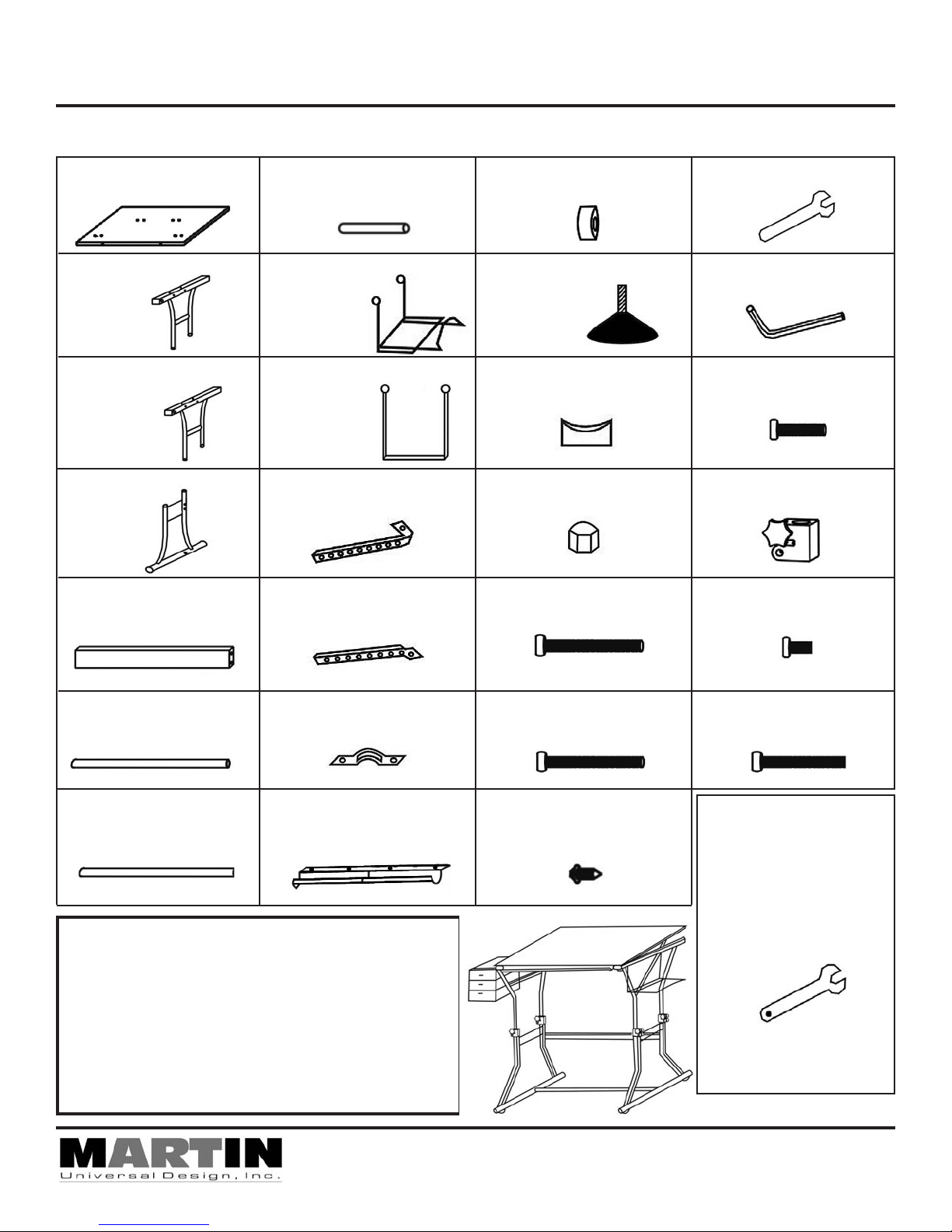
Parts List
[1] - 23.5” x 35.5” Top
(1 piece)
[2] - Upper Base left End
(1 pieces)
[3] - Upper Base right
End (1 pieces)
[4] - Lower Base End
(2 pieces)
[5] - Cross Support
(1 piece)
[8] - Drawer Support Rods
(2 pieces)
[9] - Media Supports
(1 pieces)
[10] - Drawer Supports
(2 pieces)
[11] - Left Tilt mechanism
(1 piece)
[12] - Right Tilt mechanism
(1 piece)
[15] - Plastic Thick Washer
(2 - pieces)
[16] - Floor Guides
(4 pieces)
[17] - Floor Support Spacer
(2 pieces)
[18] - End Cap Nut
(2 pieces)
[19] - 6x50mm Bolt
(2 pieces)
[22] - Wrench (1 piece)
[23] - Allen Wrench
(1 piece)
[24] - 6x25mm Bolt
(2 piece)
[25] - Collars
(4 pieces)
[26] - 6x8mm Bolt
(6 pieces)
[6] - Base Floor Support
(1 piece)
[7] - Board Brace
(1 piece)
IMPORTANT
If you have difficulty assembling your U-DS92ST
Creative Center or need customer service
assistance. Please call:
Martin Universal Design, Inc.
Customer Service Hot Line at
1-313-895-0700.
If you need additional parts, it is not necessary
to contact your dealer, our Customer Service Rep.
will forward them to you immediately.
[13] - Board Brace Clamp
(2 pieces)
[14] - Tool Trough
(1 piece)
4444 Lawton Avenue, Detroit, MI 48208 USA • Tel:(313)895-0700/Fax:(313)895-0709
Email: Custservmud@aol.com • visit us at www.MartinUniversalDesign.com
[20] - 6x45mm Bolt
(8 pieces)
[21] - 4x12mm Screw
(14 pieces)
[27] - 6x40mm Bolt
(2 pieces)
[A] - Drawers
(1 set - these need
to be assembled)
Please see assembly
sheet for drawers.
Pg. 1
August 07- RPI
Page 2
U-DS92ST Ashley Creative Center With Padded Stool
20
Assembly Instructions
4
FIG 1
17
19
20
25
5
4
6
17
19
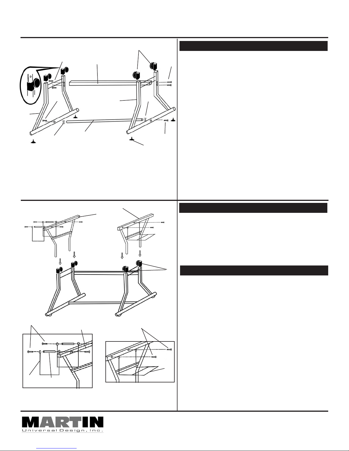
STEP 1] Assembly Base of Table
Begin by attaching the Cross support (part 5) to each Base
20
End Unit (part 4). Secure cross support to leg of base units
with [2] 6x45mm bolts (part 20). Tighten with Allen Wrench.
See FIG 1.
Continue by taking the [2] Lower Base End units (part 4) and
attach the base floor support (part 6) to the lower Base End
units using a floor support spacer (part 17) between each end
of floor support and base end unit. Secure with [2] 6x50mm
bolts (part 19). Tighten with Allen Wrench. See FIG 1.
Continue by attaching [4] floor guides (part 16) into the base
by screwing in the guides into the specified holes on the
bottom of the base units.
16
Complete Step 1 by attaching the [4] collars (part 25) onto
each of the [4] ends of the lower portion of the base. Tighten
lower bolt found below knob on collar. This secures collar to
leg. Repeat with all 4 collars. See FIG 1.
NOTE: Knobs on collars are to secure table at desired
height.
2
3
STEP 2] Assembly Top portion of Base
Take each upper Base ends (part 2 & 3) attach to base
assembly by inserting the ends of upper base units into the
[4] collars (part 25) found on the base assembly. Tighten
knobs on collars to secure. See FIG 2.
24
10
FIG 3A
25
STEP 3] Attach Drawer & Media Support
Continue by attaching Drawer Supports (part 10) to Upper
Portion Base Unit (part 2). Begin by securing the Drawer
Support Rod (part 8) to the base end unit using [1] 6x45mm
bolt. Insert the bolt (part 20) through the inside edge of the
FIG 2
26
base end unit (part 2), through the hole in the Drawer Support
(part 10) and secure into the Drawer Support Rod. Secure
with Allen Wrench.
Continue by securing other end of Drawer support to Drawer
Support Rod using a 6x25mm bolt. Secure to Drawer
Support Rod with Allen Wrench.
Repeat with second Drawer Support See FIG 3A.
Attach Media Support (part 9) to Upper Portion Base unit
9
(part 3) using [2] 6x8mm bolts. Secure with Allen Wrench.
See FIG 3B.
8
FIG 3B
Pg. 2
4444 Lawton Avenue, Detroit, MI 48208 USA • Tel:(313)895-0700/Fax:(313)895-0709
Email: Custservmud@aol.com • visit us at www.MartinUniversalDesign.com
August 07- RPI
Page 3

U-DS92ST Ashley Creative Center With Padded Stool
Assembly Instructions
FIG 4
13
21
13
21
7
1
21
PLEASE NOTE: Lay Table Top onto flat carpeted surface
or empty flattened carton insuring top wont scratch,
making sure the T-nut holes are facing up.
Take the Board Brace (part 7) along with the [2] Board Brace
Clamps. Attach the Board Brace to the Drawing Top
(part 1) using [1] Board Brace Clamp (part 13) and [5]
4x21mm screws per clamp to underside of table top in predrilled holes. PLEASE NOTE: Make sure the 2 holes near
the end on the Board Brace are positioned as shown.
Tighten screws to secure. See FIG 4.
13
FIG 4B
PLEASE NOTE: The [1] screw (part 21) that is attached to
the inside section of each clamp (part 13) See FIG 4B. Please
secure these screws and then LOOSEN 1/4 TURN.
This allows for the table top to move easily when making a
tilt adjustment later on.
21
STEP 5] Attaching Tool Trough
Attach Tool Trough (part 14) to the front edge of the Drawing
Top by using [4] 4x12mm screws. Tighten to secure.
See FIG 5
STEP 4] Attaching Board Brace
FIG 5
FIG 6
14
26 26
STEP 6] Attach Tilt Mechanisms to Top
With Drawing Top (part 1) laying on floor, attach
Tilt Mechanisms (part 11 & 12) to Drawing top using [2]
6x8mm Bolts (part 26) in pre-drilled T-Nut holes found in
Drawing Top. Tighten to secure. Repeat with second tilt
mechanism. See FIG 6
Pg. 3
August 07- RPI
Page 4

U-DS92ST Ashley Creative Center With Padded Stool
Assembly Instructions
20
1
27
FIG 7
15
20
20
18
18
15
27
STEP 7] Attach Top to Base
After Attaching the Tilt mechanism to the table top, you must
attach the opposite end of the tilt mechanism to the base.
Using [1] 6x40mm bolt (part 27), [1] Thick Plastic Washer
(part 15) and [1] End Cap Nut (part 18) per mechanism.
Insert the bolt through the outer side of the base add the thick
washer (position the rounded inverted end of the washer
up against the base unit to fit flush with the base. Continue
inserting the bolt through the tilt mechanism hole and secure
with End Cap nut. See FIG 7
Tighten but DO NOT TIGHTEN to much, otherwise the tilt
mechanism will not adjust smoothly or evenly. Repeat with
other side. AGAIN DO NOT TIGHTEN TO MUCH OTHER-
WISE TILT MECHANISM WILL NOT WORK SMOOTHLY.
Secure Top to base by attaching the Board Brace (part 7)
to the Base. Secure by attaching a 6x45mm Bolt (part 20)
through the board Brace hole and into the hole on the end of
the upper portion of the end base unit. See FIG 7B.
Tighten to secure.
FIG 7B
STEP 8] ADJUSTMENTS
HEIGHT ADJUSTMENT:
To adjust the height of your table - loosen the knobs on the collars found on the base of the table and lift the table top to
desired height.
TILT ADJUSTMENT:
To adjust the tilt of your table top, grab the back edge of the table top and lift the top with [2] hands to the maximum tilt and
then back down to your desired position. NOTE: You must lift the table top all the way up before lowering it to the
desired tilt level.
NOTE: If the top does not seem to move smoothly - this means you are NOT holding the top balanced with both
hands. Make sure your hands are positioned evenly. This will make the adjustment easier.
LEVELING FLOOR GUIDES:
If your floor is uneven, you can adjust the floor guides by loosening the floor guides to make up for the uneven floor.
August 07- RPI
Pg. 4
4444 Lawton Avenue, Detroit, MI 48208 USA • Tel:(313)895-0700/Fax:(313)895-0709
Email: Custservmud@aol.com • visit us at www.MartinUniversalDesign.com
Page 5

U-DS92ST Ashley Creative Center With Padded Stool
Drawer Assembly Instructions
Drawer Parts & Quantity
A B
Top - 2 Pieces Inside Section - 2 Pieces Drawers - 3 PiecesBottom - 2 Pieces
WARNING: READ ALL INSTRUCTIONS FIRST BEFORE ASSEMBLING DRAWERS.
ONCE PIECES ARE SNAPPED TOGETHER THEY ARE SECURED.
Assemble your drawers by
taking the section [A] and
snapping into place by lining up the tabs with the
grooves in the outside edge
of section piece [B].
Complete by snapping
section [C] onto section A&B.
A
B
C
D
Finish by sliding the
[3] Drawers into the
drawer bank assembly.
If you have difficulty assembling your U-DS92ST Drawers or need customer service assistance.
Please call: Martin Universal Design, Inc. Customer Service Hot Line at 1-313-895-0700.
If you need additional parts, it is not necessary to contact your dealer,
C
After proper assembly
the drawers should look
like the above illustration.
D
IMPORTANT
our Customer Service Rep. will forward them to you immediately.
4444 Lawton Avenue, Detroit, MI 48208 USA • Tel:(313)895-0700/Fax:(313)895-0709
Email: Custservmud@aol.com • visit us at www.MartinUniversalDesign.com
Revised June 07- RPI
Page 6

U-DS92ST Ashley Creative Center With Padded Stool
Stool Assembly Instructions
B
A
F
F
E
C
E
E
F
Begin by taking Part A & B,
position them as shown above.
Insert part C between A & B.
Secure by inserting the [4]
6x25mm bolts (part E) through
the inside back through to the
outside and thread into Part F.
Tighten to secure.
GG
G
F
D
Attach Stool seat to stool
assembly by laying the seat
onto the floor and place the
stool assembly over it. Secure
with [4] 6x32mm bolts (part
G). Tighten down to secure.
Double check that all bolts are
tightened. Once that is complete
Turn your stool over onto its legs
and use.
If you have difficulty assembling your U-DS92ST Stool or need customer service assistance.
Please call: Martin Universal Design, Inc. Customer Service Hot Line at 1-313-895-0700.
If you need additional parts, it is not necessary to contact your dealer,
our Customer Service Rep. will forward them to you immediately.
4444 Lawton Avenue, Detroit, MI 48208 USA • Tel:(313)895-0700/Fax:(313)895-0709
Email: Custservmud@aol.com • visit us at www.MartinUniversalDesign.com
IMPORTANT
August 07- RPI
 Loading...