

Page 1
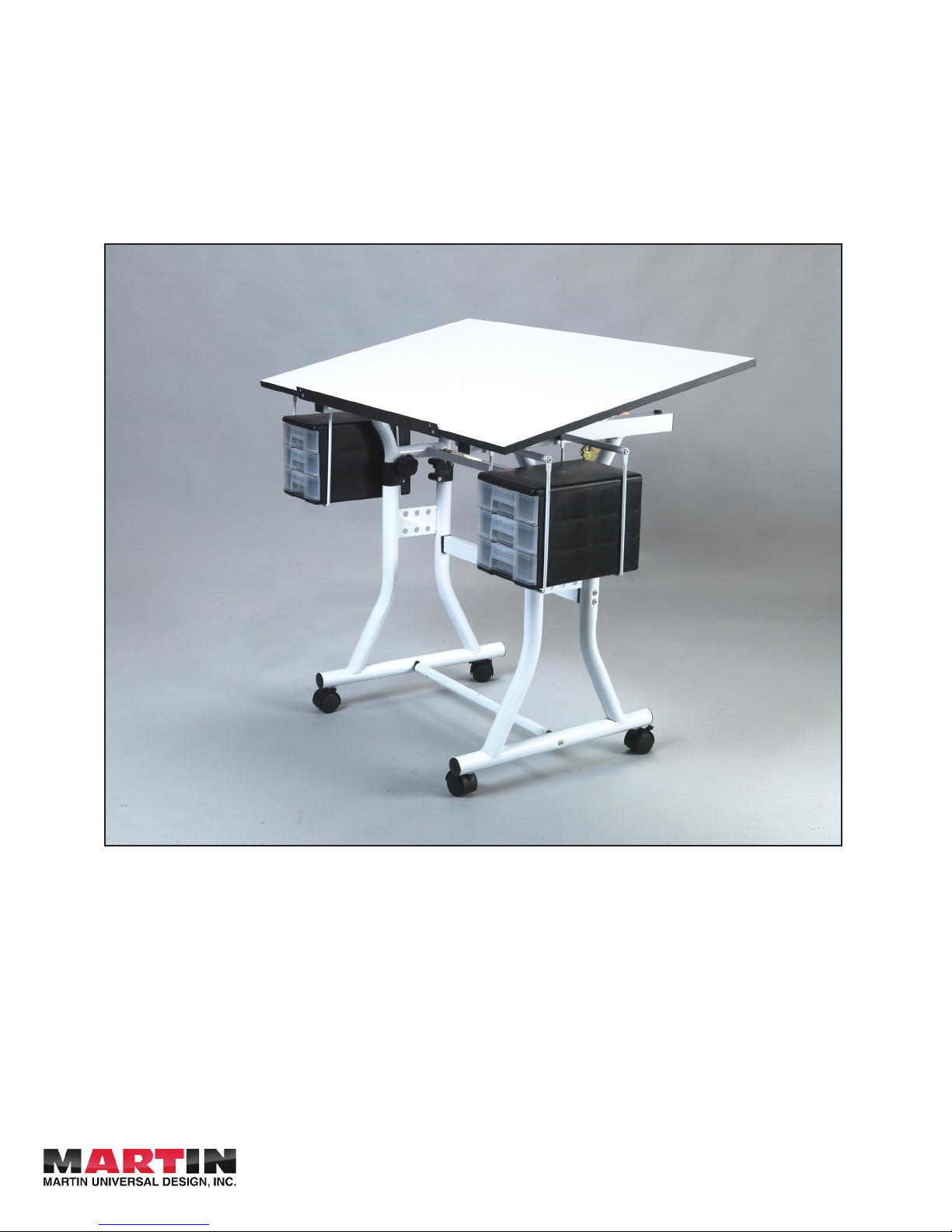
Creation Station Table
Assembly Instructions
Video Assembly Instructions:
Go to www.MartinUniversalDesign.com and click on
Assembly Instructions to watch a video for HOW TO
ASSEMBLE the U-DS90W / U-DS90B, Creation Station
Table.
4444 Lawton Street, Detroit, MI, 48208 USA • Tel: 313-895-0700 • Fax: 313-895-0709
Email: CustservMUD@gmail.com • www.MartinUniversalDesign.com
IMPORTANT:
If you have difficulty assembling your U-DS90W/U-DS90B
Creative Center or need customer service assistance.
Please call: Martin Universal Design, Inc. Customer service
Hot Line at 1-313-895-0700. If you need additional parts, it
is not necessary to contact your dealer. Our customer service rep. will forward them to you immediatly.
01/2012 SM
Page 2
Page 2
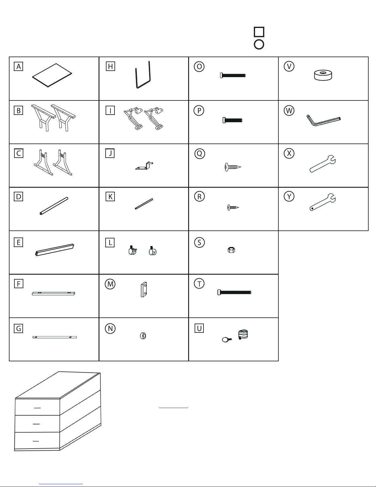
U-DS90W / U-DS90B
Creation Station Table Parts List
24”x40” Top
Upper Base End
Lower Base End
(2 pieces)
(2 pieces)
Drawer Supports
Tilt Mechanism (2 Pieces)
Top L-Bracket
(4 Pieces) 6x55mm (6 pieces) Washer (4 Pieces)
(2 Pieces)
6x28mm (8 pieces)
5x14mm
(8 Pieces)
: Table Components
: Fasteners and Tools
Allen Wrench
Wrench (10mm)
Foot Bar
Cross Support
Top Support
Pencil Ledge
Drawer Support Rods
(4 pieces)
Casters
End Caps (2 pieces)
Footbar Spacers
(4 Pieces) Nuts (4 Pieces)
Cross Support
(2 Pieces) Collars (4 pieces)
4x12mm
6x65mm (6 pieces)
Drawers:
(2 Pieces)
Wrench (12mm)
Packaged with Casters
Phillips Head screw driver
NOT INCLUDED
Please see Last Page of assembly
sheet for drawers.
01/2012 SM
Page 3
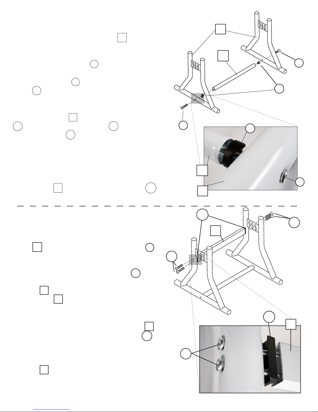
Step 1: Lower Base Ends
Fastener parts needed for this step: T= 2 ea., N=2 ea.
• Take the lower base end units (Part C ) and line
up next to each other so the welds are on the inside.
• Take 6x65mm bolt (Part T ) and insert it in the
base end from the outside. Once inserted, slide the
footbar spacer (Part N ) onto the the 6x65 mm bolt
(Part T )making sure the curved end is facing the
lower base and the at part is toward the foot bar.
• Spin foot bar (Part D ) onto the 6x65 mm bolt (Part
T ) using the Allen Wrench (Part W ) to hold the
6x65 mm bolt (Part T ) still. Be sure to leave it loose.
• Take opposite lower base end and repeat Step 1-2
with that base end.
Page 3
C
D
T
N
T
N
D
• Line up the base end and secure it loosely to the
foot bar (Part D ). using the Allen Wrench (Part W
) and be sure to leave loose for Step 2.
Step 2: Attaching Cross Support
Fastener parts needed for this step: O=4 ea. M=2 ea.
•Locate the 2 vertical holes on the Lower Base Ends
(Part C ) and insert the 6x55mm bolts (Part O )
through these holes.
• Slide on cross support end cap (Part M ) making sure curved part faces the lower base end
(Part C ) and at part faces the Cross Support (Part E ). DO NOT OVER TIGHTEN to
avoid damaging the cross support end caps.
• Line up holes on Cross Support (Part E )
O
T
C
M
O
E
M
E
and tighten with the allen wrench (Part W ).
• Place other support cap up to opposite leg, thread
bolts through the holes and tighten to cross support
(Part E )
• Go back and tighten all 6 bolts so they are snug but
again, BE CAREFUL NOT TO OVER TIGHTEN.
O
01/2012 SM
Page 4

Step 3: Attaching the Casters
• The castors (Part L ) are wrapped separately. (2 locking; 2 non-
locking)
• On the bottom of the lower base you will nd four holes one in
each corner.
• Place locking castors (Part L ) in the front (farthest away from
the cross support). This is for ease of use in moving table later.
- Tighten using wrench with hole (Part Y )
• Place the remaining non locking castors (Part L ) in rear
- Tighten using wrench with hole (Part Y )
Step 4: Attaching the Collars
U
• The Collars (Part U ) are in a separate bag.
• Loosen the lower bolt of the collar (Part U )
Page 4
L
L
L
U
• Slide the collar (Part U ) on top of the lower base
(Part C ) making sure the knobs face in so they do not
affect the drawers on the outside.
• Tighten the lower bolt with the Allen wrench (Part W )
- SNUG ONLY, DO NOT OVER TIGHTEN
• Place lower assembly off to side for now.
Step 5: Attaching Upper Base Ends
Fastener parts needed for this step: O=2 ea.
• Take one upper base end (Part B ).
- 4 Holes face towards inside.
• Place the 6X55mm bolt (Part O ) in the hole
from the outside
C
C
B
F
• Line up with Top Support (Part F ) and tighten
with Allen Wrench (Part W )
• Repeat with other side
O
B
F
O
01/2012 SM
Page 5

Step 6: Base Assembly
• Take upper assembly and line up the four
posts with the collars. Push the four posts all
the way into the lower assembly. Failure to do
so will make attaching the top (Step 9) difcult.
• Tighten knob to make snug. DO NOT OVER TIGHTEN.
Page 5
Step 7: Drawer Support
Fastener parts needed for this step: P= 4 ea., T= 4 ea., V= 4 ea.
• Take 6X65mm bolt (Part T ) and insert through
the inside of the upper base end (Part B )
• Slide on Washer (Part V )
• Slide on [1/ea] Drawer Support (Part H )
• Spin on Drawer Support Rod (Part K )
• From the outside of the base, secure with a
6X28mm Bolt (Part P )
• Repeat this process 3 more times till you have
all 4 drawer supports hanging (two on each upper
base end).
K
V
V
K
P
H
T
H
P
K
P
H
KHV T
01/2012 SM
Page 6

Step 8: Tilt Mechanisms
Fastener parts needed for this step: Q= 4 ea.
• Carefully place Top (Part A ) upside down on carpeted area or empty carton to avoid scratching top
surface.
• Locate the end of the table that has the predrilled
holes on the edge. These holes represent the front of
the table top.
• Line up the tilt mechanisms (Part I ) on the holes
closest to the back of the table. Place the wider side
on the table top and line up the holes making sure
the stamped part of the tilt mech is facing outwards. It
should also be extending away from you (toward the
back of the top) if you are sitting at the front of table.
Page 6
I
Q
A
I
Q
• Now secure with the screws 5x14 mm screws (Part
Q ) using a Phillips head screwdriver (not included).
• Repeat this process with the other tilt mech.
Step 9: Attaching Table Top
Fastener parts needed for this step: Q= 4 ea.
• Carefully turn over base and rest it on the tabletop so
the entire table is upside down.
• Place the Top L Brackets (Part J ) in the empty
holes on the front of the upper base end (Part B )
• Line the Top L Brackets (Part J ) up with the two pre
drilled holes closest to the front of the table.
• Using your Phillips head screw driver, secure the Top
L Brackets (Part J ) with 5x14 mm screws (Part Q ).
Q
Front
J
• Repeat with the other side.
J
Q
J
01/2012 SM
Page 7

Step 10: Attaching Tilt Mechanism to Base
Fastener parts needed for this step: S= 4 ea., P= 4 ea.
1. Carefully ip the entire table to its upright position, then
raise the tilt mechanisms so the narrow tabs rest on the top
support (Part F ) [[Please See Picture]]
2. Insert the 6x28mm bolts (Part P ) and from the bottom,
secure with the nuts (Part S ) using both the wrench (Part
X ) and Allen Wrench (Part W ).
3. Repeat these steps until all four holes are secured.
Page 7
P
P
F
F
S
Step 11: Pencil Ledge
Fastener parts needed for this step: R= 2 ea.
1. Carefully turn table over so it is standing
right side up.
2. Locate the predrilled holes on the edge of
the front of the table top (Part A )
3. Make sure lip of pencil ledge (Part G ) is
up and adjust the pencil ledge to the desired
position using the shaped holes on the pencil ledge.
P
F
S
S
A
G
Front
R
• Secure with [2] 4x12 mm screws (Part R )
using your Phillips head screw driver.
A
G
R
01/2012 SM
Page 8

Adjustments
HEIGHT ADJUSTMENT:
To adjust the height of your table - loosen the knobs on the collars found on the base of the table and
lift the table top to your desired height.
(To avoid damaging the table top, DO NOT attempt to lower the table top by forcefully pushing down
on the top when its in a locked position.)
TILT ADJUSTMENT:
To adjust the tilt of your table top, grab the back edge of the table top and lift the top with [2] hands to
the maximum tilt and then back down to your desired position. NOTE: You must lift the table top all the
way up before lowering it to the desired tilt level.
Page 8
NOTE: If the top does not seem to move smoothly - this means you are NOT holding the top balanced
with both hands. Make sure your hands are positioned evenly. This will make the adjustments easier.
In order to lower the table top, life it all the way up to its maximum height which allows the tilt mechanisms to
release from their locked position. To avoid damaging the table top, DO NOT attempt to lower the table top by
forcefully pushing down on the top when its in a locked position.
4444 Lawton Street, Detroit, MI, 48208 USA • Tel: 313-895-0700 • Fax: 313-895-0709
Email: CustservMUD@gmail.com • www.MartinUniversalDesign.com
01/2012 SM
Page 9

Drawer Assembly Instructions
Page 9
A
Top
WARNING: Read all instructions first before assembling drawers. Once pieces are snapped together they are secured.
Assemble your drawers by taking the section [A] and snapping
into place - by lining up the tabs with the grooves in the outside edge of section piece [B].
Complete by snapping section [C] onto section A&B.
Finish by sliding the [3] Clear Drawers (Part D) into the drawer
bank assembly.
B
Middle Bottom Clear Drawer
C
D
A
B
C
D
After proper assembly the drawers should
look like the above illustration.
IMPORTANT:
If you have difficulty assembling your U-DS90W/U-DS90B Creative Center or need customer service assistance.
Please call: Martin Universal Design, Inc. Customer service Hot Line at 1-313-895-0700. If you need additional
parts, it is not necessary to contact your dealer. Our customer service rep. will forward them to you immediatly.
4444 Lawton Street, Detroit, MI, 48208 USA • Tel: 313-895-0700 • Fax: 313-895-0709
Email: CustservMUD@gmail.com • www.MartinUniversalDesign.com
01/2012 SM
 Loading...