

Page 1
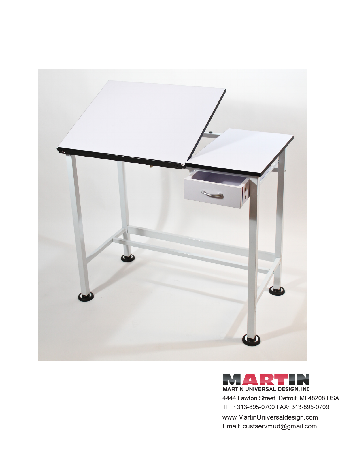
MANCHESTER SPLIT TOP
TABLE ASSEMBLY INSTRUCTIONS
U-DS1922W
IMPORTANT
If you have difculty assembling your table, or need customer service
assistance, please call: Martin Universal Design, Inc. customer service
hotline at 1-313-895-0700, or email at custservmud@gmail.com. If
you need additional parts, it is not necessary to contact your dealer. Our
Customer Serice Representative will forward them to you immediatly.
1
Page 2
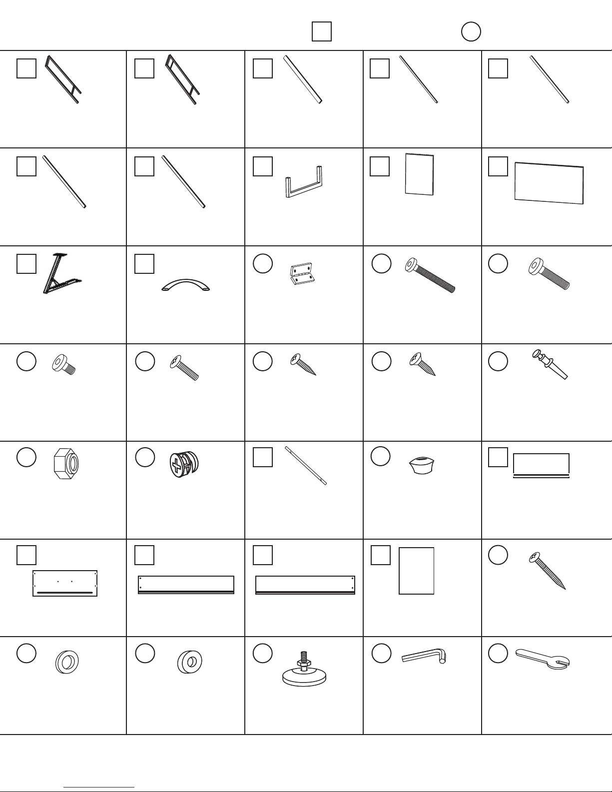
PARTS LIST
= Table Components = Fasteners and Tools
1
6
Cross Support
11
Tilt Mechanism
Left Leg
(Back Top)
2
7
Cross Support
12
Drawer Handle
Right Leg
(Back)
3
Cross Support
8
Drawer Support
13
(Bottom)
Hinge
(QTY: 2)
4
Cross Support
9
14
Bolt 6 x 50mm
(Bottom)
Drawer Top
(QTY: 14)
5
Cross Support
(Front Top)
10
Main Top
15
Bolt 6 x 28mm
(QTY: 6)
16
Bolt 6 x 8mm
(QTY: 2)
21
Locking Nut
(QTY: 2)
26
Drawer Front Panel
17
Bolt 4 x 20mm
(QTY: 2)
22
Cam
(QTY: 4)
27
Drawer Right Side Panel
18
Screw 4 x 12mm
(QTY: 3)
23
Pencil Ledge
28
Drawer Left Side Panel
19
Screw 4 x 14mm
(QTY: 8)
24
Drawer Stopper
29
Drawer Bottom Panel
20
Composite Bolt
(QTY: 4)
25
Drawer Back Panel
30
Screw 4 x 35mm
(QTY: 4)
31
Metal Washer
(QTY: 2)
32
Metal Washer
(QTY: 4)
Phillips Head Screwdriver NOT included.
33
Glides
(QTY: 4)
34
Allen Wrench
35
Wrench
2
June2013
Page 3
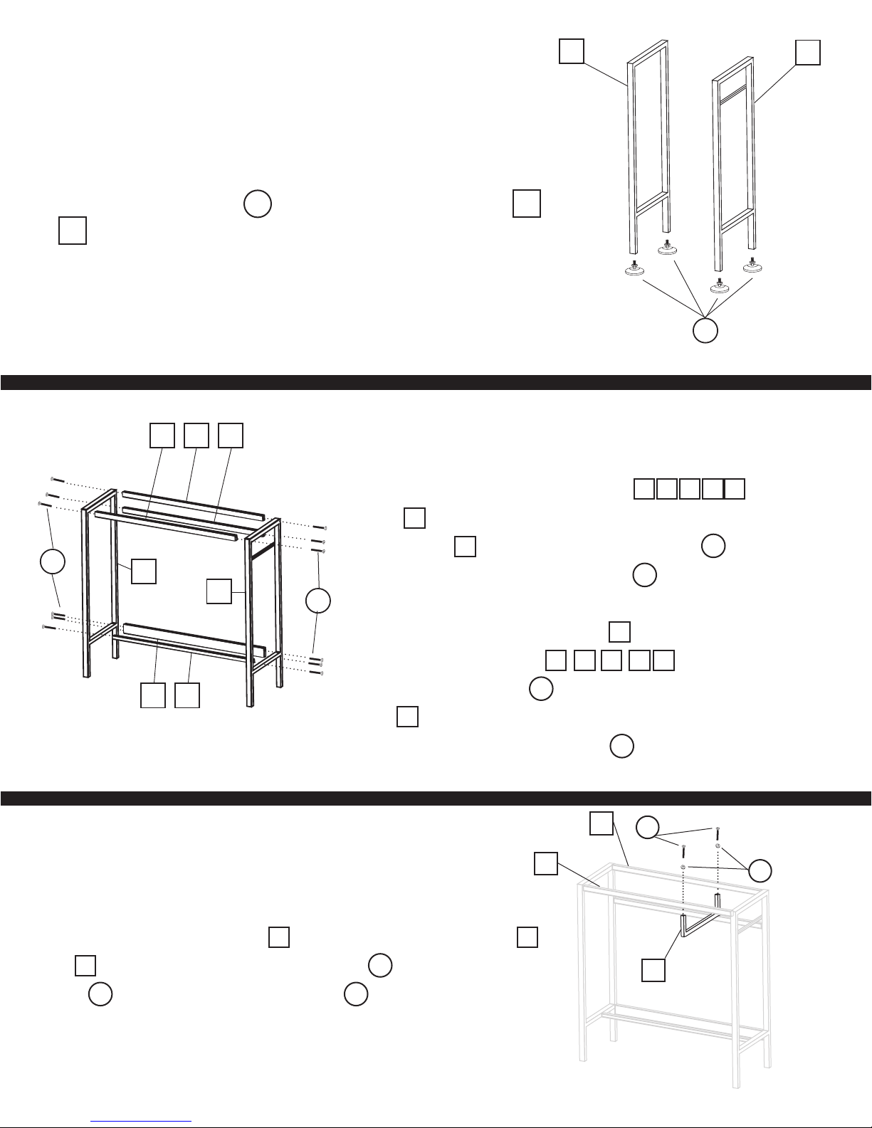
Step 1
Assemble Glides
Attach 4 oor glides (Part 33 ) to the left and right legs (Part 1
& 2 ) by tightening the glides into the specied holes at the bot-
tom.
1
33
2
14
5 637
1
4
Step 2
Assemble Table Base
A) Attach the 5 cross supports (Parts 3 4 5 6 7 ) to the left leg
(Part 1 ) by lining each up with appropriate hole. Secure each to outside
edge of Part 1 with one 6x50mm hex bolt (Part 14 ) into each hole.
Tighten hex bolts with Allen Wrench (Part 34 ).
2
14
B) Repeat with right side (Part 2 ) by attaching the other end of
the 5 cross supports (Parts 3 4 5 6 7 ) also using one each of
6x50mm hex bolts (Part 14 ) into each hole on the outside side edge of
Part 2 , lining that hole up with the hole in the end of each cross support.
Tighten bolts with Allen Wrench (Part 34 ).
6
14
Step 3
Attaching Drawer Support
Attach Drawer support guide (Part 8 ) to the base cross supports (Parts 5
and 6 ) using 1 each 6 x50mm hex bolts (Part 14 ) and metal washers
(Part 31 ). Tighten with Allen Wrench (Part 34 ).
5
8
31
June2013
3
Page 4

Step 4
11
15
Attach Tilt Mechanism and Hinges
13
13
21
19
19
A) Attach Tilt mechanism (Part 11 ) to the base. Locate the 2 holes on the top side of cross support (Part 6 ) .
Secure Tilt Mechanism to this cross support using 2 each 6x28mm bolts (Part 15 ) & 2 each locking nuts (Part 21 ).
Position locking nuts to the underside of cross supports (Part 6 ). Use wrench (Part 35 ) to hold nuts while tightening
down Hex Bolts.
B) Attach 2 hinges (Part 13 ) to front edge of cross support (Part 5 ) by lining up holes in hinge and holes in
cross support bar (Part 13 ). Secure using 2 each 4x14mm screw (Part 19 ) per hinge. Tighten with Phillips head
screwdriver.
Step 5
Attach Top Drawer
32
9
Line up the drawer top (Part 9 ) to the specied holes on table base. Once drawer top is positioned correctly, secure top
using 4 of 6x28mm bolts (Part 15 ) and 4 of the metal washers (Part 32 ). The metal washers should be positioned
between drawer top and table base.
15
4
June2013
Page 5

Step 6
Attach Main Top
10
11
16
13
13
19
A) Align holes in hinges to the holes in top board. Attach the 2 hinges (Part 13 ) to the top by using 2 each 4x14mm
screws (Part 19 ) per hinge and tighten with Phillips head screwdriver.
B) B) Align holes in tilt mechanism (Part 11 ) to threaded holes in top. After lining up holes, attach tilt mechanism to top
with 2 each 6x8mm Hex Bolts (Part 16 ) and tighten with Allen wrench.
5
June2013
Page 6

Step 7
Drawer Assembly
29
25
30
30
28
27
A) Take the back panel (Part 25 ) and side panels of the drawer (Parts 27 & 28 ) and To secure drawer assembly,
insert 2 each 4x35mm screws (Part 30 ) into each drawer side panel and tighten with Phillips head screwdriver.
B) Slide the drawer bottom (Part 29 ) into the grooves on the side of the drawers and into the back panel of the drawer.
*Please note that the white side should be up for inside drawer.
26
20
C) Take the drawer front panel (Part 26 ) and insert 4 threaded composite bolts (Part 20 ). Use Phillips head screw-
driver to secure threaded connector pins.
6
June2013
Page 7

17
27
22
D) Insert cams (Part 22 ) into the holes found on each side panel, making sure the holes of the T-nuts (Part 22 )
line up with the holes on the outer edge of the drawer sides.
E) Attach sides of drawers (Parts 27 & 28 ) to the drawer front (Part 26 ) by inserting threaded connection
pins (Part 20 ) into the holes on the outside edge of the drawer sides. *Please note that the grooves in each side must be
20
28
12
26
20
22
lined up with each other to allow the drawer bottom to be installed. To secure, tighten the T-nuts (Part 22 ) with Philipps
head screwdriver until tight.
F) Attach drawer handle (Part 12 ) to front drawer panel using 2 of 4x20mm bolts (Part 17 ).
Step 8
Attaching Pencil Ledge and Drawer Stopper
23
18
18
24
Attach pencil ledge (Part 23 ) to the front edge of table top, using two 4x12mm screws (Part 18 ).
After sliding drawer to table, attach drawer stopper (Part 24 ) to the left side of drawer, using 4x12mm screw (Part 18 )
and tighten it with Phillips head screwdriver.
7
June2013
 Loading...