

Martin RUSH CS300 WIDE, RUSH CS600 GRAZE, RUSH CS600 WIDE, RUSH CS900 WIDE, RUSH CS1200 WIDE User Manual
...Page 1
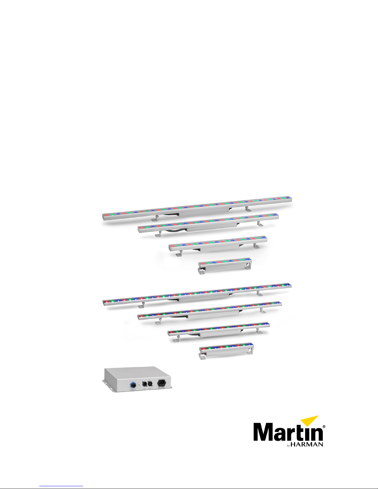
RUSH® CS Series
CS300 GRAZE & WIDE
CS600 GRAZE & WIDE
CS900 GRAZE & WIDE
CS1200 GRAZE & WIDE
CS PSU Power Supply Unit
User manual
Page 2
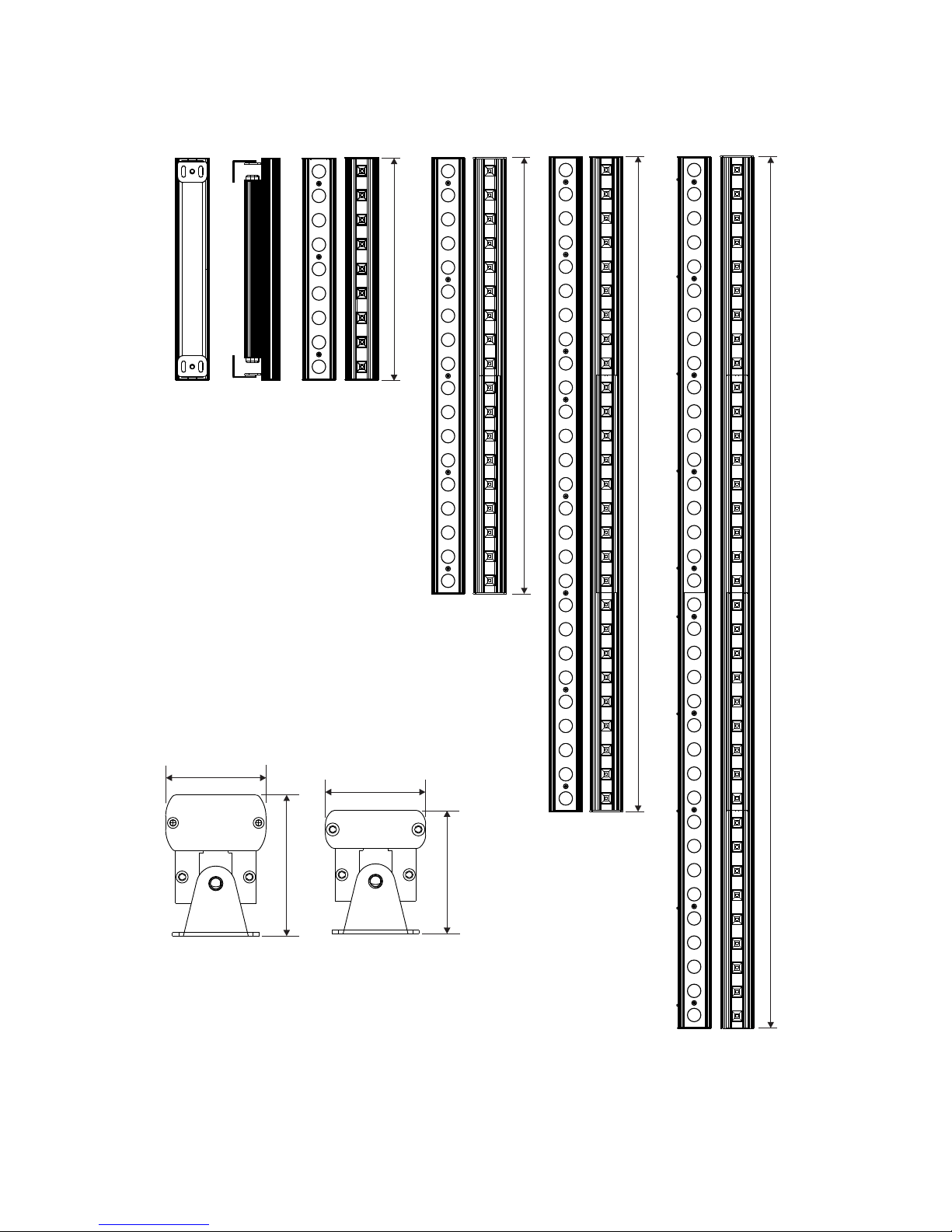
Dimensions
46.0
Graze
CS300
CS600
CS900
CS1200
Wide
46.0
65.0
57.0
1203
903
603
303
Page 3
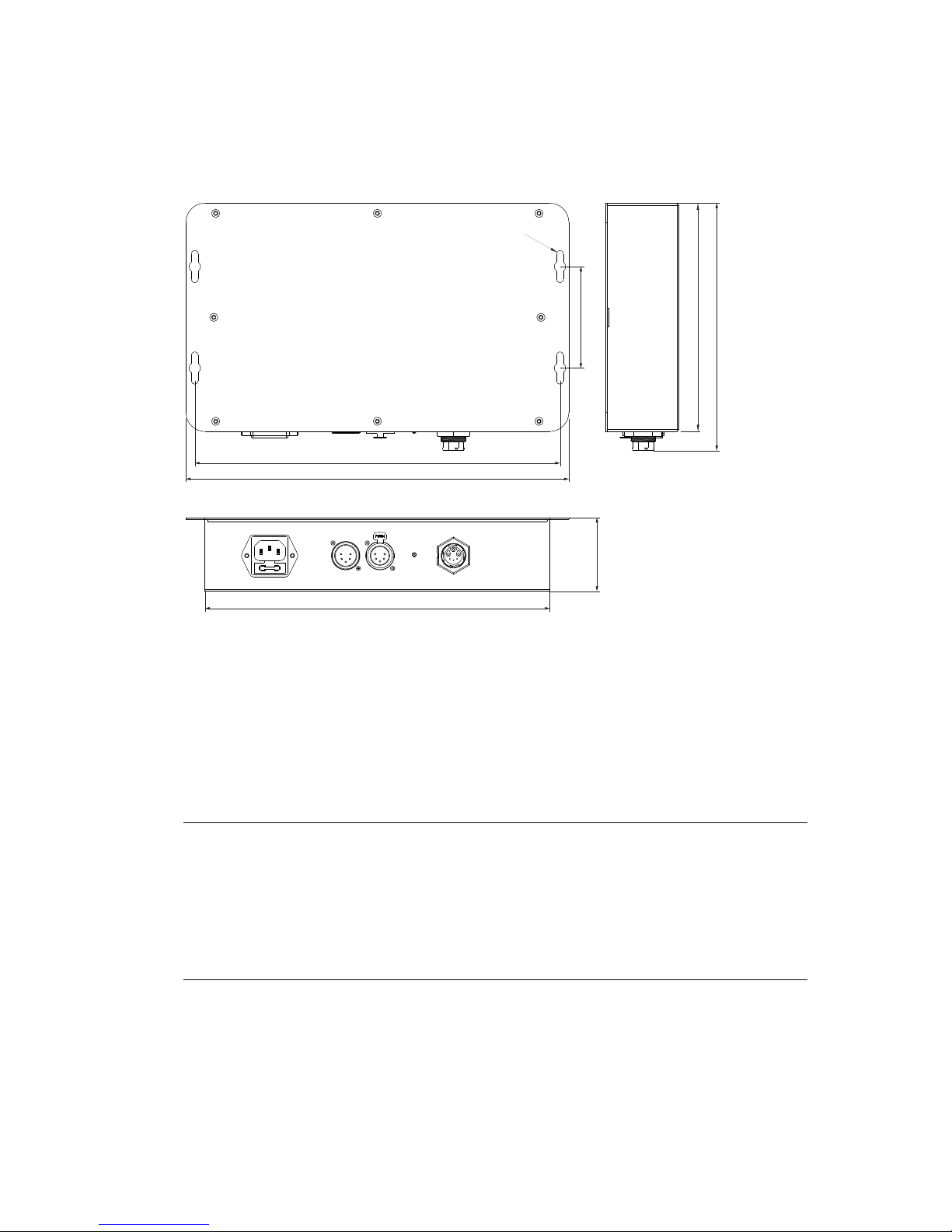
CS PSU Power supply unit
302.0
180
58.0
195.0
272.0
288.0
80.0
R2.8
Information subject to change without notice. HARMAN Professional Denmark ApS disclaims liability for
any injury, damage, direct or indirect loss, consequential or economic loss or any other loss occasioned by
the use of, inability to use or reliance on the information contained in this document.
©2015-2018 HARMAN Professional Denmark ApS. All rights reserved. Martin® is a registered trademark
of HARMAN Professional Denmark ApS registered in the United States and/or other countries. Features,
specifications, and appearance are subject to change without notice.
RUSH® CS Series User Manual – Revision C
All dimensions are given in millimeters
For mounting bracket dimensions see page 11
Page 4

Table of contents
Dimensions ............................................................................................................... 2
Safety information ..................................................................................................... 5
Introduction ............................................................................................................... 8
Before using the product for the first time ........................................................... 8
Fixture overview .................................................................................................. 9
Physical installation ................................................................................................ 11
Fixture location .................................................................................................. 11
Mounting the fixture ........................................................................................... 11
AC power and data connection to PSU .................................................................. 13
Power requirements .......................................................................................... 13
Connecting fixtures ................................................................................................. 13
Data network requirements ............................................................................... 14
Setup ...................................................................................................................... 15
RDM and Martin® M-PC ................................................................................... 15
Step one: scanning for devices on the data link ................................................ 15
Setting DMX mode ............................................................................................ 15
Setting DMX addresses .................................................................................... 15
Dimming control ................................................................................................ 16
Temperature status ........................................................................................... 16
Overall fixture status ......................................................................................... 16
RDM .................................................................................................................. 17
Maintenance ........................................................................................................... 18
Cleaning ............................................................................................................ 18
DMX protocol .......................................................................................................... 19
6 channel mode ................................................................................................ 19
3 channel mode ................................................................................................ 19
Specifications ......................................................................................................... 21
Page 5
RUSH® CS Series User Manual 5
Safety information
WARNING!
Read the safety precautions in this manual before installing, operating or servicing
this product.
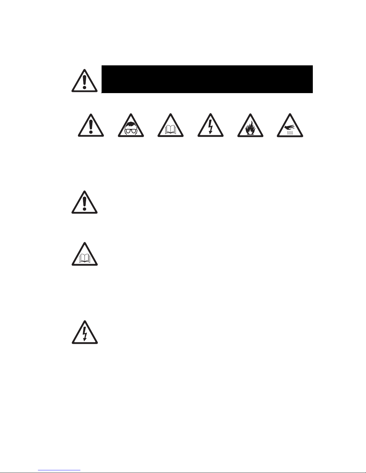
The following symbols are used to identify important safety information on the product and in this manual:
Warning!
Safety hazard.
Risk of severe
injury or
death.
Warning!
Powerful light
emission. Risk
of eye injury.
Warning!
See user
manual for
important
safety
information.
Warning!
Hazardous
voltage. Risk
of lethal or
severe electric
shock.
Warning!
Fire hazard.
Warning!
Hot surfaces.
Warning! Risk Group 2 product according to EN 62471. Do not look directly into the beam.
Do not view the light output with optical instruments or any device that may concentrate
the beam.
This lighting fixture is for professional use only and must be installed by a qualified
technician. It is not for household use. It presents risks of severe injury or death due to fire
hazards, electric shock and falls. It can create a fire hazard or a risk of eye injury if the
safet
y p
recautions below are not followed.
Install, operate and service RUSH® by Martin® products only as directed in their user
manuals, or you may create a safety hazard or cause damage that is not covered by
product warranties. Follow the safety precautions listed below and observe all warnings in
this manual and printed on the product. Keep this user manual for future use.
For the latest user documentation and other information about this and all Martin®
products, please visit the Martin® website at http://www.martin.com
If you have any questions about how to install, operate or service the fixture safely, please
contact your Martin® distributor (see www.martin.com/distributors for details) or call the
Martin® 24-hour service hotline on +45 8740 0000, or in the USA on 1-888-tech-180.
Respect all locally applicable laws, codes and regulations when installing, operating or
servicing the fixture.
Protection from electric shock
Ensure that the fixture is electrically connected to ground (earth).
Disconnect the fixture from AC power when not in use.
Never connect or disconnect a live Power + Data Cable. Shut down power to the fixtures
before connecting or disconnecting cables.
Do not open the fixture or remove any cover. Refer any service operation not described in
this manual to an authorized Martin Service partner.
Shut down power to the entire installation at the main power distribution board and lock out
power before carrying out any installation or maintenance work.
Use only a source of AC power that complies with local building and electrical codes and
has both overload and ground-fault (earth-fault) protection.
Isolate the fixture from power immediately if any seal, cover, cable, or other component is
damaged, defective, deformed or showing signs of overheating. Do not reapply power until
repairs have been completed
Page 6
6 RUSH® CS Series User Manual
Before using the fixture, check that all power distribution equipment and cables are in
perfect condition and are of suitable type for the location (including water, pollution,
temperature and UV resistance).
Do not immerse the fixture in water or any other fluid, or install it in a location where
floodin
g
may occur.
Protection from burns and fire
Do not operate the fixture if the ambient temperature (Ta) exceeds 45° C (113° F).
The surface of the fixture can reach up to 55° C (131° F) if the fixture is operated at the
maximum permitted ambient temperature. Allow the fixture to cool for at least 5 minutes
before handling.
Install the fixture on a non-combustible surface (brick, concrete, plaster etc.) only.
Do not aim the fixture towards combustible materials (fabric, wood, paper etc.) that are
within 10 cm (4 in.) of the fixture.
Keep the fixture well away from flammable materials (volatile liquids etc.).
Ensure that there is free and unobstructed airflow around the fixture.
Allow at least 0.1 m (4 in.) free space around the fixture.
Do not attempt to bypass thermostatic switches or fuses.
Do not modify the fixture in any way not described in this manual or install other than
genuine Martin® parts. Do not stick filters, masks or other materials onto any lens or other
optical component. Use only accessories approved by Martin® to modify the light beam.
Protection from eye injury
The CS Series fixtures fall into Risk Group 2 according to EN62471. To minimize the risk
of eye irritation or injury, disconnect the fixture from power at all times when the fixture is
not in use, and provide well-lit conditions to reduce the pupil diameter of anyone working
on or near the fixture.
The light from the LED emitters is possibly hazardous and may be harmful to the eyes. Do
not stare directly into the product’s light output.
Do not look at the light output with magnifiers, telescopes, binoculars or similar optical
instruments that may concentrate the light output.
Ensure that persons are not looking directly into the fixture when the product lights up
suddenly. This can happen when power is applied, when the product receives a DMX
signal, or when certain control menu items are selected.
WIDE fixtures
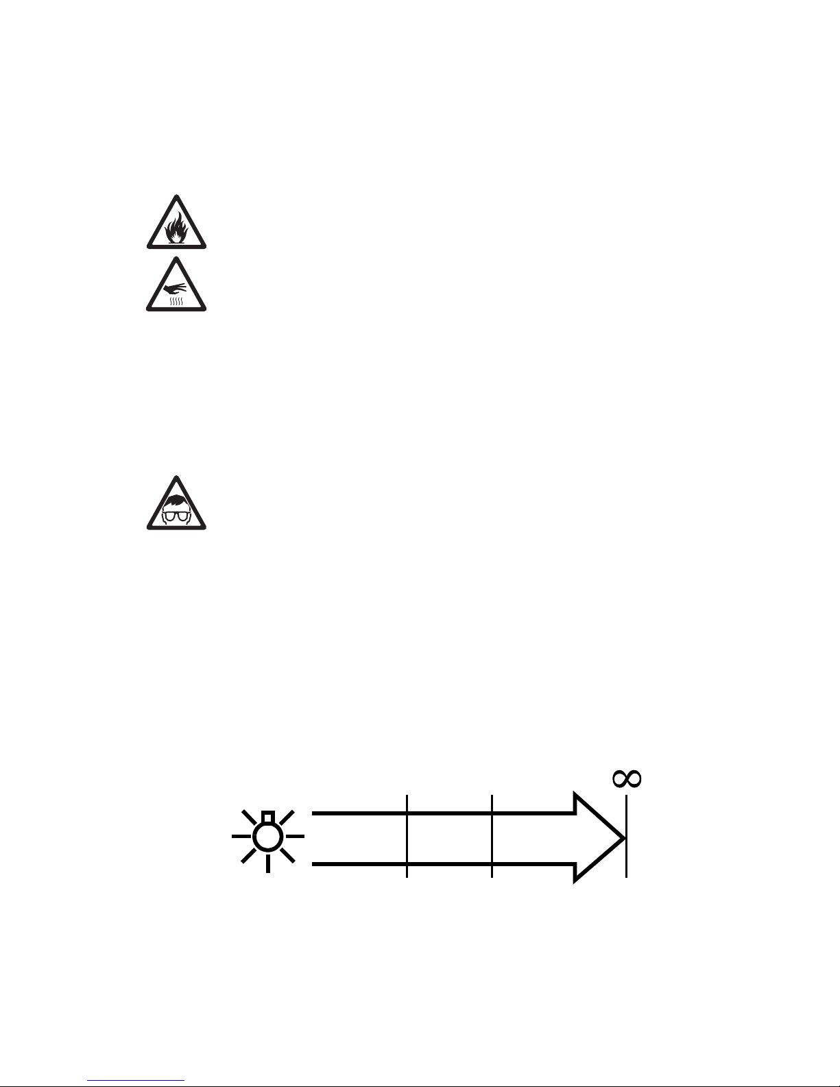
The CS Series Wide fixtures fall into the following risk groups according to EN62471 at the
distances indicated below. Position the CS Series Wide fixtures so that prolonged staring
into the light output at less than 336mm (13.3 in.) from the fixture is not expected.
RISK GROUP2RISK GROUP
1
336 mm
(13.3 in.)
3.4 m
(11.2 ft.)
RISK GROUP
EXEMPT
Page 7
RUSH® CS Series User Manual 7
GRAZE fixtures
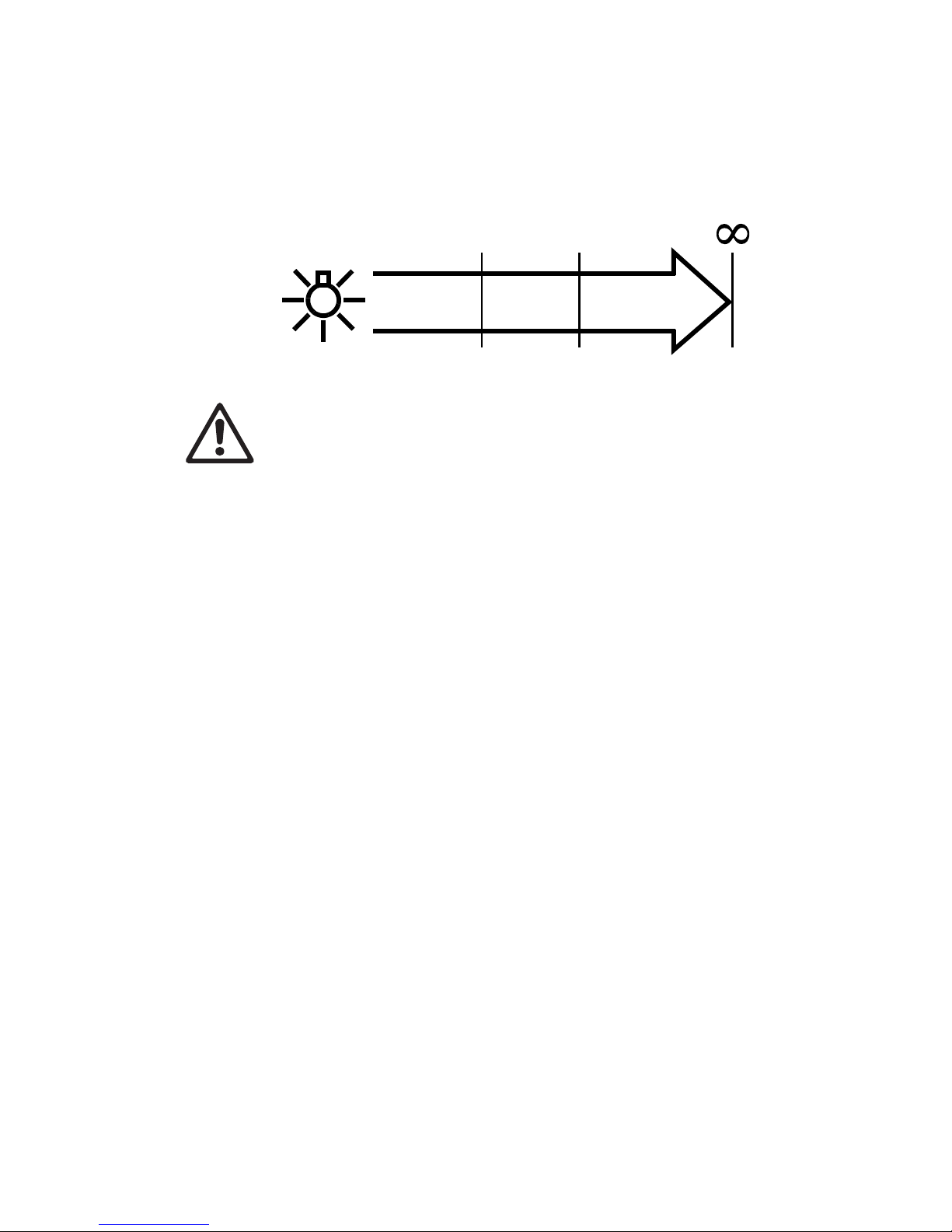
The CS Series Graze fixtures fall into the following risk groups according to EN62471 at
the distances indicated below. Position the CS Series Graze fixtures so that prolonged
staring into the light output at less than 2.4 m (7.9 ft.) from the fixture is not expected.
RISK GROUP2RISK GROUP
1
2.4 m
(7.9 ft.)
23.5 m
(77.1 ft.)
RISK GROUP
EXEMPT
Protection from injury
Fasten the fixture securely to a fixed surface or structure when in use. The fixture is not
portable when installed.
Ensure that all supporting structures, surfaces, fasteners and lifting equipment can bear
the weight of all the devices they are intended to support plus an adequate safety margin,
and that they conform to local building and safety regulations.
Ensure that any accessory such as a glare shield is securely fastened.
Block access below the work area and work from a stable platform whenever installing,
setting, adjusting, or cleaning the fixture.
Do not operate the fixture with missing or damaged covers, shields or any optical
component.
If an operating problem occurs, stop using the fixture immediately and disconnect it from
power. Do not attempt to use a fixture that is obviously damaged.
Page 8

8 RUSH® CS Series User Manual
Introduction
The RUSH® CS Series from Martin® is a line of rugged LED-based lighting fixtures with a remote power
supply unit. Fixtures are available in 300 mm (1 ft.), 600 mm (2 ft.), 900 mm (3 ft.) and 1200 mm (4 ft.)
length models, each with either wide or graze optics. Wide optic models are designed for a range of
indirect lighting applications. Graze models are designed for illumination of walls or other surfaces and
have an asymmetric 18° x 65° beam-angle.
The fixtures are powered by a remote power supply unit (PSU) which is controlled by DMX and configured
using RDM (Remote Device Management). Multiple fixtures can be linked together making for simple
installation of long runs. Each PSU can power up to 10 meters (32 ft.) of LED fixtures.
The RUSH® CS Series system features:
• Long-life, high output Cree LEDs
• Remote 100-240 V, 50/60 Hz auto-ranging AC power supply
• Low voltage 36V supply to fixtures
• Easy wiring with integral combined low voltage power and data cables
Each fixture is supplied with two hinged mounting brackets.
Before using the product for the first time
1. Read ‘Safety information’ on page 5 before installing, operating or servicing the fixture.
2. Unpack and ensure that there is no transportation damage before using the fixture. Do not attempt to
operate a damaged fixture.
3. Before operating, ensure that the voltage and frequency of the power supply match the power
requirements of the fixture.
4. If fixtures are exposed to a sudden temperature change, give them time to warm or cool to the
ambient temperature before applying power. This will help avoid damage due to condensation.
5. Check the support pages on the Martin® website at www.martin.com for the most recent user
documentation and technical information about the fixture. Martin® user manual revisions are
identified by the revision letter at the bottom of the inside cover.
Page 9

RUSH® CS Series User Manual 9
Fixture overview
2
2
1
3
4
1
Number Description
1 Mounting bracket
2 Tilt lock screws
3 Power/data input connector (blue)
4 Power/data output connector (black)
RUSH® CS Series LED fixture parts Identification
1
2
3
4
5
Number Description
1 Mains power input (Fuse: T6.3A)
2 DMX input
3 DMX output
4 Mains power indicator light
5 Data/power output to fixtures
RUSH® CS PSU Parts Identification
Page 10

10 RUSH® CS Series User Manual
Fixture output Fixture input (blue) Power supply output
Number Description
1 Data ground
2 Data -
3 Data +
4 Not used
5 Not used
6 +36 V power
7 Not used
8 0 V power
RUSH® CS Series combined power/data connector
The 5-pin XLR connectors for DMX use standard pinout.
Pin Number Description
1 Data ground
2 Data -
3 Data +
4 Not connected
5 Not connected
RUSH® CS Series 5-pin XLR pinout
Page 11

RUSH® CS Series User Manual 11
Physical installation
Warning! Read ‘Safety information’ on page 5 before installing the fixture.
Warning! The safety and suitability of lifting equipment, installation location, anchoring
method, mounting hardware and electrical installation are the responsibility of the installer.
All local safety regulations and legal requirements must be observed when installing and
connecting the RUSH® CS Series. Installation must be carried out by qualified
p
rofessionals only.
Contact your Martin supplier for assistance if you have any questions about how to install this product
safely.
Fixture location
RUSH® CS Series fixtures are intended for interior use only. Do not install outside or in damp or humid
locations. The fixtures and Power Supply Unit require free and unobstructed airflow around them to ensure
adequate cooling.
Observe the following limitations in selecting a location:
• Respect the limitations listed under Safety information’ on page 5.
• Do not locate the fixture in an unventilated space.
Mounting the fixture
Warning! All fasteners used to mount RUSH® CS Series fixtures must
be strong enough to mount the fixture safely. Install a washer directly
under the head of each fastener when anchoring the mounting bracket
to the installation surface.
Positioning the mounting brackets
The fixture’s mounting brackets must be securely anchored
to a suitable support. The mounting surface must be hard,
fixed and flat. For bracket dimensions see illustration on
right.
The fixture can be mounted at any angle. The mounting
brackets allow the fixture to be manually tilted 90° either side
of central position for beam aiming adjustment.
Fasten the fixture securely with suitable mechanical
fasteners. Do not stand it on a surface or leave it where it
can be moved or fall over. Ensure that the surface and all
fasteners used can support at least 10 times the weight of all
fixtures and equipment they will support.
M6
23.5
5.5
dia. 6.5
Page 12

12 RUSH® CS Series User Manual
1
1
You can slide the mounting brackets along the fixture by loosening the slide grubscrew (1) using a 2mm
hex key (not supplied). Ensure that the grubscrew is re-tightened to lock the bracket in the desired
position.
2
2
3
3
You can reverse the orientation of the mounting brackets so that the flanges face inwards by removing the
M6 hex-head bolts (2) and washers (3). In most cases, leaving the mounting flanges on the outside is
preferable because it provides easier access to the hinge bolts for tilt adjustment.
2
3
Reassemble the bracket with the mounting flange and bolt (2) on the inside, ensuring that you fit the
washer (3) as shown above, between the bracket and the flange.
Fastening to the mounting surface
To mount a fixture on a suitable surface:
1. Loosen the hinge bolts and tilt the mounting brackets to 90 degrees. This allows you easy access to
screw the brackets to the mounting surface.
2. Fasten the mounting brackets loosely to the mounting surface using two suitable fasteners in each
bracket.
3. Refer to ‘Connecting fixtures’ on page 13 and connect the fixture power + data input to the output of
the previous fixture.
4. Adjust the position of the mounting brackets as necessary. Tighten the fasteners in the flange and the
slide lock grubscrew on each mounting bracket.
5. Pivot the mounting brackets to the desired tilt angle and tighten the hinge bolts.
Page 13

RUSH® CS Series User Manual 13
AC power and data connection to PSU
Warning! Read ‘Safety information’ on page 5 before installing the fixtures and PSU.
Electrical installation must be carried out by qualified professionals only. Lock out power to
the entire installation before working on cables and connections.
For protection from dangerous electric shock, the PSU must be grounded (earthed). The
AC power distribution system must be fitted with current overload and ground-fault (earthfault) circuit breakers as well as a means to isolate fixtures from power and lock out power
during service.
In the RUSH® CS Series system, AC power and DMX control data are connected to the RUSH® CS
Power Supply Unit (PSU). The PSU then sends low voltage DC power and DMX data to one or more
fixtures using a custom 6-pole connector.
Important! Do not connect or disconnect a live power and data cable. Shut down power to the installation
before connecting or disconnecting cables.
The RUSH® CS PSU accepts AC power at 100 - 240 V nominal, 50 or 60 Hz. Do not connect to power at
any other voltage or frequency.
There is no power on/off switch. Power is applied to the PSU and fixtures as soon as they are connected
to power. Provide a means to disconnect or shut down power to fixtures that is easily accessible and is
located close to the fixtures.
Do not use an external dimming system to supply power to the system, as this may cause damage to the
system that is not covered by the product warranty.
Power requirements
The RUSH® CS PSU must be supplied with AC mains power at 100 - 240 V nominal, 50/60 Hz using
either a grounded single-phase (live, neutral, ground/earth) distribution system or one phase of a
grounded three-phase (3 live phases, neutral, ground/earth) distribution system.
Connecting fixtures
All fixtures are fitted with captive input and output cables, carrying data and power using a custom 6-pole
connector. Fixtures can be connected end to end using the captive cables, or if the fixtures need to be
separated they can also be connected using the 1 m (3.2 ft.), 5 m (16 ft.) or 10 m (32 ft.) extension cables
listed under ‘Accessories’ on page 23.
The blue connector is the input connector and the black connector is the output to the next fixture in the
chain.
Maximum total length of fixtures
The PSU can power up to 10 meters of RUSH® CS fixtures. For example, eight 1200 mm fixtures, eleven
900 mm fixtures, seventeen 600 mm fixtures or thirty-two 300 mm fixtures.
If you connect too many fixtures, the PSU will shut down to protect itself. When the extra load is removed,
the PSU will resume normal operation.
Maximum total length of cable
If you connect additional extension cables between the PSU and the first fixture, or between fixtures, a
maximum length of cable applies due to voltage drop in the cable. If the cable is too long, the fixtures
furthest from the power supply will lose intensity. This will be particularly visible on the green and blue
LEDs, so colors will tend to shift towards red.
The maximum recommended length of one system is 50 m (164 ft.) including both cable and fixtures.
Page 14

14 RUSH® CS Series User Manual
Data network requirements
The DMX lighting controller connects to the RUSH® CS Series PSU using the 5-pin XLR plug. Further
DMX equipment may be connected using the 5-pin XLR socket.
The following considerations must be taken into account when laying out the data network:
• 512 DMX channels are available in a single DMX universe. Each time the combined channel
requirements of a group of connected fixtures exceeds 512, an additional DMX universe will be
required.
• You can reliably connect up to 32 fixtures in a single daisy chain.
• Use RS-485 data cable. RS-485 cable has low capacitance and a characteristic impedance of 85 to
150 Ohms. It is electrically shielded and has at least 1 twisted pair of conductors. The minimum
recommended wire size is 0.25 mm2 (24 AWG) for runs up to 200 meters (1000 ft.) and 0.32 mm2
(22 AWG) for runs up 500 meters (1640 ft.).
• Branches may be added to the link using an opto-isolated splitter. Use an RDM-compatible amplifiersplitter such as the Martin® RDM 5.5 Splitter. Each branch may itself connect up to 32 fixtures.
• An RDM amplifier may also be used to extend a network beyond 500 meters (1640 ft.) or to connect
up to 32 additional fixtures to the daisy chain.
• Long parallel runs of AC power and control data cables may cause interference on the data link and
must be avoided. Even if not required by law, use separate conduits for power and data cables.
Page 15

RUSH® CS Series User Manual 15
Setup
Warning! Read ‘Safety information’ on page 5 before operating the fixture.
This section explains the fixture settings and utilities that the user has access to via RDM
(Remote Device Management according to ANSI/ESTA E1.20).
RDM and Martin® M-PC
RUSH® CS Series fixtures require an RDM-compatible controller to check and alter fixture settings, send
control commands and retrieve fixture data. Martin® offers a range of suitable controllers.
Martin® M-PC is a Windows-based application available from Martin® that lets you set up, manage and
control a lighting installation from a PC that is connected to the installation via a DMX data link. To use
Martin® M-PC, connect a PC running the application to the data link via a USB-to-DMX interface box such
as the Martin® M-DMX (see ‘Related Items’ on page 23).
A full list of the RDM functions that RUSH® CS Series fixtures support is given at the end of this chapter.
These functions are generally referred to using the more specific term ‘PIDs’ or ‘Parameter IDs’.
Step one: scanning for devices on the data link
Before you can communicate with fixtures using RDM, you must send a scan command (also called a
device discovery command) to all the devices on the data link so that the RDM controller can identify
them. It does this by retrieving each device’s factory-set unique identifier (UID). This process can take
some time depending on the number of devices on the link.
To identify the fixtures on the link:
1. Check that the fixtures are correctly connected to the RDM controller on the data link and that power
is applied to all fixtures.
2. In Martin® M-PC, go to RDM CONTROLLER DISCOVER DEVICES.
3. Give the controller time to identify the devices on the link and prepare for communication with the
devices.
Setting DMX mode
This command lets you set the DMX mode of fixtures on the data link. Because DMX mode affects the
number of DMX channels a fixture uses, it will affect the assignment of DMX addresses to fixtures. You
should therefore set fixtures’ DMX mode before you set their DMX addresses.
The CS PSU can be set to either 3Ch. DMX mode – ”1: 3ch-Slot” (factory default setting) or 6Ch. DMX
mode – ”2: 6ch-Slot”. 6ch. mode offers additional control functions but uses more DMX channels. See
the 'DMX protocol’ section on page 19 for an overview of the functions available and number of DMX
channels used.
You can set the DMX mode of one fixture by sending a unicast RDM command to that one fixture only, or
you can set the DMX mode of all the fixtures on the data link by sending a broadcast RDM command to all
the devices on the link.
Procedures vary in different controllers, but to set the DMX mode in Martin® M-PC:
1. Go to RDM CONTROLLER Scan Properties Device Info Change personality.
2. Select EXD MODE or STD MODE.
3. Press ENTER to confirm your selection.
Setting DMX addresses
This command lets you set the DMX addresses of fixtures on the data link. From the factory the DMX
address is set to 001.
A fixture’s DMX address is the first DMX channel it uses to receive data communication. It uses this
channel and the channels immediately above it. A RUSH CS fixture uses six DMX channels, so if it has
DMX address 001, it will use channels 001, 002, 003, 004, 005 and 006. DMX address 007 will be
available as a DMX address for the next fixture on the data link. If this fixture also uses six DMX channels,
the next available DMX address will be 013, and so on.
Page 16

16 RUSH® CS Series User Manual
You can set the DMX address of one fixture by sending a unicast RDM command to that one fixture only,
or you can set all the fixtures on the data link to the same DMX address by sending a broadcast RDM
command to all the devices on the link. If all the fixtures have the same DMX address, they will behave
identically and you will not be able to control any single fixture independently.
To set a DMX address:
1. In Martin® M-PC, go to RDM CONTROLLER Scan Properties Advanced Choose PID
Set DMX START ADDRESS.
2. In the Message column, enter the DMX address that you want to give to the fixture (or give to all the
fixtures if you are sending a broadcast command).
3. Press RDM SET to confirm your selection.
The Response column will show the setting result as either Success or Failed.
Dimming control
You can control the output intensity of the fixtures on the link via RDM.
You can control the intensity of one fixture by sending a unicast RDM command to that one fixture only, or
you can control all the fixtures on the data link by sending a broadcast RDM command to all the devices
on the link.
To control intensity:
1. In Martin® M-PC, go to FUNCTION MANUAL CONTROL DMX TRANSMITTER
2. Scroll to an intensity level from 0 to 255.
3. Press ENTER to confirm your selection.
Temperature status
Using RDM you can read the temperature status of the fixture: This tells you whether the fixture LEDs are
operating at the correct temperature or whether they have overheated.
To retrieve this information:
1. In Martin® M-PC, go to RDM CONTROLLER DISCOVER DEVICES Get Sensor value.
2. Use the arrow keys on the keyboard to scroll and display temperature status for all fixtures.
Overall fixture status
You can display general status information for a fixture.
To retrieve this status data:
1. In Martin® M-PC, go to RDM CONTROLLER DISCOVER DEVICES Status check.
2. Overall fixture status is displayed.
Page 17

RUSH® CS Series User Manual 17
RDM
As a minimum, RUSH® CS Series fixtures support the following RDM functions:
Device discovery
DISC_UNIQUE_BRANCH
DISC_MUTE
DISC_UN_MUTE
Device management
GET SET
QUEUED_MESSAGE
STATUS_MESSAGES
STATUS_ID_DESCRIPTION
SUPPORTED_PARAMETERS
DEVICE_INFO
DEVICE_MODEL_DESCRIPTION
MANUFACTURER_LABEL
DEVICE_LABEL
SOFTWARE_VERSION_LABEL
BOOT_SOFTWARE_VERSION_ID
BOOT_SOFTWARE_VERSION_LABEL
DMX_PERSONALITY
DMX_START_ADDRESS
DEVICE_HOURS
IDENTIFY_DEVICE
LAST_STATE
DIMMER_CURVE
Page 18

18 RUSH® CS Series User Manual
Maintenance
Warning! There are no user-serviceable parts inside. Do not open the housing. Refer any
service operation not described in this manual to Martin Professional™ or its authorized
service agents.
Installation, on-site service and maintenance can be provided worldwide by the Martin
Professional™ Global Service organization and its approved agents, giving owners access
to Martin’s expertise and product knowledge in a partnership that will ensure the highest
level of performance throughout the product’s lifetime. Please contact your Martin® supplier
for details.
Never try to repair the fixture by yourself as this may result in damage or malfunction and it
may potentially void your product warranty. The only service operation the user can carry
out on RUSH® CS Series fixtures is occasional cleanin
g
.
Be aware that the output of LEDs, like all light sources, changes gradually over many thousands of hours
of use. If you require products to perform to very precise color specifications, you may eventually need to
make small readjustments at the lighting controller.
The light source in this product is not user-replaceable. When the light source LEDs reach the end of their
service life, they may be replaced only by Martin® Service, an authorized Martin® Service agent or a
similarly qualified person.
Cleaning
Regular cleaning is essential for fixture life and performance. Buildup of dust and dirt degrades the
fixture’s light output and cooling ability.
Cleaning schedules will vary greatly depending on the operating environment. It is therefore impossible to
specify precise cleaning intervals for the RUSH® CS Series. Inspect fixtures within their first few weeks of
operation to see whether cleaning is necessary. Check again at frequent intervals. This procedure will
allow you to assess cleaning requirements in your particular situation. If in doubt, consult your Martin®
dealer about a suitable maintenance schedule.
Do not use products that contain solvents, abrasives or caustic agents for cleaning, as they can cause
surface damage to the fixture. The aluminum housing and front cover can be cleaned with a soft cloth
moistened with mild detergents such as those for washing cars.
To clean the fixture housing and front cover:
1. Isolate the PSU from AC power and allow the fixtures to cool for 20 minutes.
2. Wipe each fixture clean with a soft dry or damp cloth.
Updating firmware
If Martin® releases updated firmware for this fixture, you can install it using the Martin® Companion
application running on a Windows PC. See www.martin.com for details.
Page 19

RUSH® CS Series User Manual 19
DMX protocol
6-channel mode
The DMX control allows 0 to 100% intensity control of red, green and blue. 0 to 100% master dimming is
provided using 16-bit control (two DMX channels). The final control channel allows five fixed color
temperatures of white light to be produced – when this channel is set to a value above zero, the Red,
Green and Blue control channels are overruled and have no effect.
Channel Value Function
1 0-255 Dimmer: 0-100%
2 0-255 Dimmer Fine: 0-100%
3 0-255 Red: 0-100% (if channel 6 = 000)
4 0-255 Green: 0-100% (if channel 6 = 000)
5 0-255 Blue: 0-100% (if channel 6 = 000)
6 000
001-051
052-102
103-153
154-204
205-255
Color temperature OFF
White 2800K
White 3200K
White 4000K
White 5600K
White 7200K
3-channel mode (default setting)
The DMX control allows 0 to 100% intensity control of red, green and blue.
Channel Value Function
1 0-255 Red: 0-100%
2 0-255 Green: 0-100%
3 0-255 Blue: 0-100%
Page 20

20 RUSH® CS Series User Manual
Page 21

RUSH® CS Series User Manual 21
Specifications
Physical
CS300 Wide
Length ............................................................................................................................. 303 mm (11.9 in.)
Width ................................................................................................................................... 46 mm (1.8 in.)
Height ...................................................................................................... 57 mm (2.2 in.) including bracket
Weight ................................................................................................................................. 0.8 kg (1.8 lbs.)
CS300 Graze
Length ............................................................................................................................. 303 mm (11.9 in.)
Width ................................................................................................................................... 46 mm (1.8 in.)
Height ...................................................................................................... 65 mm (2.6 in.) including bracket
Weight .................................................................................................................................... 1 kg (2.2 lbs.)
CS600 Wide
Length ............................................................................................................................. 603 mm (23.7 in.)
Width ................................................................................................................................... 46 mm (1.8 in.)
Height ...................................................................................................... 57 mm (2.2 in.) including bracket
Weight ................................................................................................................................. 1.1 kg (2.4 lbs.)
CS600 Graze
Length ............................................................................................................................. 603 mm (23.7 in.)
Width ................................................................................................................................... 46 mm (1.8 in.)
Height ...................................................................................................... 65 mm (2.6 in.) including bracket
Weight ................................................................................................................................. 1.4 kg (3.1 lbs.)
CS900 Wide
Length ............................................................................................................................. 903 mm (35.6 in.)
Width ................................................................................................................................... 46 mm (1.8 in.)
Height ...................................................................................................... 57 mm (2.2 in.) including bracket
Weight ................................................................................................................................. 1.5 kg (3.3 lbs.)
CS900 Graze
Length ............................................................................................................................. 903 mm (35.6 in.)
Width ................................................................................................................................... 46 mm (1.8 in.)
Height ...................................................................................................... 65 mm (2.6 in.) including bracket
Weight .................................................................................................................................... 2 kg (4.4 lbs.)
CS1200 Wide
Length ........................................................................................................................... 1203 mm (47.4 in.)
Width ................................................................................................................................... 46 mm (1.8 in.)
Height ...................................................................................................... 57 mm (2.2 in.) including bracket
Weight ................................................................................................................................. 1.8 kg (4.0 lbs.)
CS1200 Graze
Length ........................................................................................................................... 1203 mm (47.4 in.)
Width ................................................................................................................................... 46 mm (1.8 in.)
Height ...................................................................................................... 65 mm (2.6 in.) including bracket
Weight ................................................................................................................................. 2.5 kg (5.5 lbs.)
Power Supply Unit
Length ............................................................................................................................. 302 mm (11.9 in.)
Width .........................................................................................................................
........ 195 mm (7.7 in.)
Height .................................................................................................................................. 58 mm (2.3 in.)
Weight ................................................................................................................................. 4.2 kg (9.3 lbs.)
Dynamic Effects
Intensity ......................................................................................................................................... 0 - 100%
Color mixing ........................................................................................................................................ RGB
Color temperature control ......................................................... Off, 2800K, 3200K, 4000K, 5600K, 7200 K
Page 22

22 RUSH® CS Series User Manual
Control and Programming
Control systems .........................................................................................................................DMX, RDM
DMX channels ........................................................................................................................................ 3, 6
DMX compliance ....................................................................................................... USITT DMX512/1990
RDM compliance ....................................................................................................................... ANSI E1.20
Optics
CS300/CS600/CS900/CS1200 Wide
Light source ....................................................................................................... CREE XP-E2 LEDs R/G/B
Beam angle .......................................................................................................................................... 124°
Minimum LED lifetime ................................................................. 50 000 hours (to >70% luminous output)*
CS300/CS600/CS900/CS1200 Graze
Light source ....................................................................................................... CREE XP-E2 LEDs R/G/B
Beam angle ................................................................................................................................... 18° x 65°
Minimum LED lifetime ................................................................. 50 000 hours (to >70% luminous output)*
*Figure obtained under manufacturer's test conditions
See www.martin.com for full photometric specifications.
Construction
Housing ........................................................................................................................................ Aluminum
Finish .................................................................................... Clear anodized (standard) or white (optional)
Lens ......................................................................................................................... Frosted polycarbonate
Ingress protection ................................................................................................................................. IP20
RoHS compliant
Installation
Orientation ............................................................................................................................................ Any
Mounting ........................................................... Direct with included brackets and user-supplied fasteners
Minimum distance to illuminated surfaces .................................................................................0.2 m (8 in.)
Connections
Mains input .......................................................................................................................... C13 IEC 60320
DMX input and output .................................................................................................................. 5-pin XLR
Fixture DC power and data in/thru ........................................................................ 8-pin custom connectors
Electrical (RUSH® CS Series PSU)
AC power ..................................................................................................... 100 -240 V nomin
al, 50/60 Hz
Power supply unit ............................................................................... Auto-ranging electronic switch-mode
DC output voltage ................................................................................................................................ 36 V
Maximum output current ...................................................................................................................... 12 A
Maximum power consumption........................................................................................................... 485 W
Mains inlet fuse ..................................................................................................................... 250 V, T 6.3 A
Typical power consumption (RUSH® CS Series fixtures)
Fixture power consumption .......................................................... 12 W per foot +/- 1 W*, PF 0.97 +/- 0.05
*Power figures are typical, not maximum. Measurements made at nominal voltage. Allow for +/- 10%
deviation. PF = Power factor.
Thermal
Cooling ....................................................................................................................................... Convection
Maximum surface temperature.............................................................................................. 55° C (131° F)
Maximum ambient temperature (Ta max.) ............................................................................ 45° C (113° F)
Minimum ambient temperature (Ta min.) ............................................................................. -30° C (-22° F)
Page 23

RUSH® CS Series User Manual 23
Approvals
PSU
EU Safety .................................................................................................................................. EN60950-1
EU EMC ..................................................................................EN 61000-4-2, EN61000-4-4, EN61000-4-5
US Safety ...................................................................................................................................UL60950-1
US EMC ................................................................................................................ CFR 47 Part 15 Class A
Canadian Safety .................................................................................................... CSA C22.2 No. 60950-1
Australia/NZ .................................................................................................................................... Pending
Wide & Graze fixture
EU Safety .............................. EN60598-2-1, EN62031, EN61347-1, EN61347-2-11, EN 62471, EN62493
EU EMC ................................................... EN55015, EN55103-2, EN55032, EN61000-3-2, EN61000-3-3,
EN61547, EN61000-4-2, EN61000-4-4, EN61000-4-5
US Safety ....................................................................................................................................... UL 2018
US EMC ................................................................................................................ CFR 47 Part 15 Class A
Canadian Safety ............................................................................................................ CSA C22.2 No. 9.0
Australia/NZ .................................................................................................................................... Pending
Included Items
User manual
Two adjustable mounting brackets
Power cables (supplied with RUSH CS Series PSU)
Power input cable, US type: IEC C13 female to NEMA 5-15P male, 1.5 m (4.9 ft.)
Power input cable, universal: IEC C13 female to bare ends, 1.5 m (4.9 ft.)
Accessories
Cables
RUSH® Power + Data Extension Cable, 8-pin custom connectors, 1 m (3.3 ft.) .................. P/N 91611846
RUSH® Power + Data Extension Cable, 8-pin custom connectors, 5 m (16.4 ft.) ................ P/N 91611847
RUSH® Power + Data Extension Cable, 8-pin custom connectors, 10 m (32.8 ft.) .............. P/N 91611848
Related Items
Martin® Companion Windows application ................................................................. See www.martin.com
Ordering Information
Wide Lighting Fixtures
RUSH® CS300 Wide, 124° (1 ft., RGB) ............................................................................... P/N 90480175
RUSH® CS600 Wide, 124° (2 ft., RGB) ............................................................................... P/N 90480185
RUSH® CS900 Wide, 124° (3 ft., RGB) ............................................................................... P/N 90480195
RUSH® CS1200 Wide, 124° (4 ft., RGB) ............................................................................. P/N 90480205
Graze Lighting Fixtures
RUSH® CS300 Graze, 18°x 65° (1 ft., RGB) ....................................................................... P/N 90480170
RUSH® CS600 Graze, 18°x 65° (2 ft., RGB) ....................................................................... P/N 90480180
RUSH® CS900 Graze, 18°x 65° (3 ft., RGB) ....................................................................... P/N 90480190
RUSH® CS1200 Graze, 18°x 65° (4 ft., RGB) ..................................................................... P/N 90480200
Power Supply Unit
RUSH® CS Series PSU ....................................................................................................... P/N 90480210
Specifications subject to change without notice. For latest product specifications, see www.martin.com
Page 24

24 RUSH® CS Series User Manual
Disposing of this product
Martin® products are supplied in compliance with Directive 2012/19/EC
of the European Parliament and of the Council of the European Union on
WEEE (Waste Electrical and Electronic Equipment), where applicable.
Help preserve the environment! Ensure that this product is recycled at
the end of its life. Your supplier can give details of local arrangements for
the disposal of Martin products
Photobiological Safety Warning
The label shown below is displayed on this product. If it becomes difficult or impossible to read, it must be
replaced using the illustration below to reproduce new labels sized 16 x 38 mm (each label), in black on a
yellow background
.
RUSH® CS Series from Martin®
Made in China
Page 25

Page 26

Page 27

Page 28

www.martin.com · Olof Palmes Allé 18 · 8200 Aarhus N · Denmark
Tel. +45 8740 0000 · Fax +45 8740 0010
 Loading...