

Page 1

MARTIN® PIT VIPER™
Pre-Cleaner
Installation instructions
M3735UK
Page 2

© Martin Engineering GmbH M3735UK-09/15
Page 3

1 Table of contents
1 Table of contents ......................................................... 1
2 Introduction ..................................................................3
2.1 About these installation instructions .............................. 3
2.1.1 Scope ............................................................................ 3
2.1.2 Copyright ....................................................................... 3
2.1.3 Exclusion of liability ....................................................... 3
2.1.4 Reference to additional documents ............................... 4
2.1.5 Classification of the hazards.......................................... 5
2.2 Intended usage.............................................................. 6
2.2.1 Conveyor systems with open transfer systems ............. 6
2.2.2 Usage in explosion-protected areas .............................. 6
2.2.3 Restrictions on the use of the product ........................... 6
2.3 Occupational safety ....................................................... 7
2.3.1 Safety information, occupational safety ......................... 7
2.3.2 Duties of the owner-operator......................................... 8
2.3.3 Authorised personnel ..................................................... 8
3 Description of the product .......................................... 9
3.1 Design and function....................................................... 9
3.2 Tensioners..................................................................... 9
3.3 Type clarification.......................................................... 10
4 Preparing for the installation .................................... 11
4.1 Before the installation.................................................. 11
4.1.1 Required materials and tools ....................................... 11
4.1.2 Preparatory measures ................................................. 11
5 Installation ..................................................................13
5.1 Safety information........................................................ 13
5.2 Installation process...................................................... 14
5.2.1 Determination of the installation position..................... 15
5.2.2 Installing the tensioner ................................................. 16
5.2.3 Installing the pre-cleaner ............................................. 17
5.2.4 Centring the blade ....................................................... 19
5.2.5 Aligning the mainframe in parallel to the head pulley .. 19
5.2.6 Aligning the mainframe in parallel to the
head pulley frame ........................................................ 20
5.2.7 Tightening the pre-cleaner ........................................... 20
5.3 Operation with loading................................................. 21
5.4 Placement of the warning labels and warning trailers . 23
6 Maintenance ...............................................................24
6.1 Safety information........................................................ 24
6.2 Weekly maintenance ................................................... 24
6.3 Replacing the blades................................................... 27
7 Troubleshooting ........................................................ 30
7.1 Safety information........................................................ 30
7.2 Troubleshooting........................................................... 30
8 Storage, de-installation, disposal ............................ 32
8.1 Packing and transportation.......................................... 32
Table of contents
© Martin Engineering GmbH 1 M3735UK-09/15
Page 4

Table of contents
8.2 Storage......................................................................... 32
8.3 De-installation .............................................................. 32
8.4 Disposal ....................................................................... 32
9 Part numbers .......................................... .......... ..........33
9.1 Explanation of part numbers ........................................ 33
9.2 Inline-Reversing tensioner ........................................... 34
9.3 Martin
®
Inspection Doors.............................................. 34
9.4 Installation manuals ..................................................... 34
9.5 Accessories.................................................................. 34
9.6 Warning labels / Warning trailers ................................. 34
9.7 MARTIN
®
PIT VIPER™ Pre-Cleaner ........................... 35
10 Declaration of incorporation .....................................38
© Martin Engineering GmbH 2 M3735UK-09/15
Page 5

2 Introduction
2.1 About these installation instructions
Non-compliance with these installation instructions can result in loss
of compensation for damage and/or warranty claims.
2.1.1 Scope
These installation instructions apply solely for the product described
herein and are intended for those persons who install this product,
commission it, and monitor its usage.
2.1.2 Copyright
The products described and these installation instructions are
protected by copyright. Any reproduction without a license will be
prosecuted. All rights to the present document are reserved,
including its reproduction and/or copying in any conceivable
manner. Reprints of this document require the written consent of
Martin Engineering.
Introduction
The technical standard at the time of delivery of the product and its
technical documentation is decisive for as long as no other
information is provided. The product and documentation are subject
to technical changes without prior notification. Earlier documents
then lose their validity. Martin Engineering's General Terms of Sales
and Delivery shall apply.
2.1.3 Exclusion of liability
Martin Engineering guarantees the flawless function of its product in
accordance with its advertising, the published product information,
and its technical documentation. Martin Engineering shall assume
no liability for efficiency and flawless function if the product is used
for a purpose other than that described in the “Intended Use” section
or for damage resulting from the use of accessories and/or spare
parts which were not supplied and/or certified by Martin
Engineering.
© Martin Engineering GmbH 3 M3735UK-09/15
Page 6

Introduction
2.1.4 Reference to additional documents
The Martin Engineering products are designed for a long service life.
They conform to the state of the art in science and technology and
were thoroughly inspected before shipment. In addition to this,
Martin Engineering constantly performs product and market
research for continuous product development.
Martin Engineering offers competent support whenever
malfunctions and/or technical problems occur. Suitable actions are
taken immediately. The warranty provisions of Martin Engineering
apply and can be sent to you as needed.
Reference is made in these installation instructions to the following
documents:
• Installation instructions for the MARTIN
®
Inspection door,
Publication no. M3127.
• Installation manual for MARTIN
®
TWIST™ Tensioner:
Publication no. M3296.
• Installation manual for MARTIN
®
Cable Tensioner:
Publication no. M3734.
The following standards and directives were complied with in the
preparation of these installation instructions:
• EU Machinery Directive (2006/42/EC)
• ISO/IEC Guide 37 “Installation instructions for products
used by final consumers”, 1995 Edition
• DIN 1421 “Organisation and numbering in texts”, Edition
1983-01
• DIN/EN 12100 “Machine safety - basic definitions, general
design guidelines”, Edition 2013-08
• DIN/ISO 16016 “Technical product documentation Protection notices for restricting the use of documents and
products”, Edition 2007-12
• DIN/EN 60204-1 “Safety of machines - Electrical
Equipment of Machines, Part 1 General requirements”,
Edition 2007-06
• DIN EN 82079-1 - Creation of user manuals - Structuring,
content and presentation, Part 1 General principles and
detailed requirements.
© Martin Engineering GmbH 4 M3735UK-09/15
Page 7
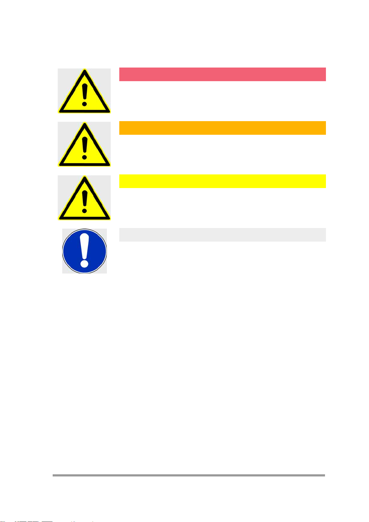
2.1.5 Classification of the hazards
DANGER!
Represents an immediately threatening danger which leads to
serious bodily injuries or death if not avoided.
WARNING!
Represents a possibly hazardous situation which could lead to
serious bodily injuries or death if not avoided.
CAUTION!
Represents a possibly hazardous situation which could lead to
minor bodily injuries and/or property damage if not avoided.
Introduction
NOTE
Contains comments about the installation and/or the product's
usage to point out situations which cause neither personal injury
nor property damage but include important information.
© Martin Engineering GmbH 5 M3735UK-09/15
Page 8

2.2 Intended usage
Introduction
2.2.1 Conveyor systems with open transfer systems
The MARTIN® PIT VIPER™ belt cleaner is used to clean conveyor
belt by scrapping off clinging materials. The cleaner can be installed
on conveyors with belt widths up to 2400 (3000) mm and a belt
speed of up to 5 m/s.
Every other usage of this product is deemed misuse. Please contact
Martin Engineering customer service if you would like to use this
product for a different purpose. We will be happy to assist you with
the product configuration.
These installation instructions describe the installation on conveyor
systems with encapsulated transfer systems. Various MARTIN
Inline mount plates can be used on open transfer systems.
Martin Engineering or one of its representatives can assist with the
position or with special solutions in cases where the installation
conditions are complicated such as insurmountable static
components or a head pulley as the tensioning station.
2.2.2 Usage in explosion-protected areas
This product can also be used in potentially explosive areas under
certain conditions. Contact Martin Engineering for more information
on usage in potentially explosive areas.
2.2.3 Restrictions on the use of the product
The product specified here may only be used within the scope of the
specifications referred to above. Usage in a higher equipment
protection category or under other operating conditions than those
specified by Martin Engineering shall be deemed misuse and is only
permitted if approved by Martin Engineering.
®
© Martin Engineering GmbH 6 M3735UK-09/15
Page 9

2.3 Occupational safety
2.3.1 Safety information, occupational safety
These installation instructions must be read through in their entirety
before work may be started on the product or on the conveyor
system supplied by the customer.
The owner-operator must ensure that all installation, inspection and
maintenance work is performed solely by trained specialists.
Work on conveyor systems and their accessories must always be
performed during shut-down. The procedures described in the
applicable installation instructions for shutting down the conveyor
system must always be complied with.
All of the safety devices and safeguards must be reattached and/or
made operational again immediately following completion of the
work.
The installation must be carried out to completion before the system
is started up. The flawless execution of all operating steps must be
tested before the conveyor system can be started up again. Please
observe all information on the installation and start-up of the
product.
Introduction
© Martin Engineering GmbH 7 M3735UK-09/15
Page 10

2.3.2 Duties of the owner-operator
Introduction
2.3.3 Authorised personnel
This product's owner-operator must ensure that this product is
installed, serviced and used solely by those persons who
• know the rules regarding occupational safety and accident
prevention,
• were trained on using this product and have read and
understood these installation instructions.
Personnel are considered authorised when they have suitable
training and technical experience, can demonstrate knowledge of
the applicable standards and guidelines, and are able to evaluate
tasks in order to recognise critical situations at an early stage.
Operating, maintenance and installation personnel
Personnel are considered authorised when they have been trained
on using the product and have read and understood these operating
instructions in their entirety.
© Martin Engineering GmbH 8 M3735UK-09/15
Page 11

3 Description of the product
3.1 Design and function
Der MARTIN® PIT VIPER™ Pre-Cleaner was specially developed to
simplify blade replacement and to reduce costs. It makes it possible
to quickly and easily replace the blade without any tools by removing
a single pin.
Although pre-cleaners and secondary cleaners can each be used individually, the installation of a system consisting of pre-cleaners and
secondary cleaners is recommended for an optimal cleaning result.
NOTE
An unfavourably or improperly installed product can disrupt the
conveyor process or contaminate the bulk material to be transported.
The owner-operator is responsible for taking the required countermeasures.
In the case of applications with contaminants, Martin Engineering
or one of its representatives can assist with the positioning or with
special solutions.
Description of the product
3.2 Tensioners
The cleaner and its specially developed Martin Engineering Inline
Reversing tensioners offer the best possible results and correspond
to the general state of the art.
The cleaner can be operated solely with the tensioners listed below:
•MARTIN
Part number 31443-I+E.
•MARTIN
Part number 37944.
®
TWIST™ Tensioner:
®
Cable Tensioner:
© Martin Engineering GmbH 9 M3735UK-09/15
Page 12

3.3 Type clarification
Blades for the MARTIN® PIT VIPER™ Pre-Cleaner are available in
various material designs. The required material can be selected in
accordance with the material conditions. The selection of the various
blades is listed in section 9 - “Part numbers”.
Description of the product
© Martin Engineering GmbH 10 M3735UK-09/15
Page 13

4 Preparing for the installation
4.1 Before the installation
4.1.1 Required materials and tools
Along with the standard tools, the following special equipment may
be needed for the installation and maintenance of your product.
• Lifting device with a capacity greater than the weight of the
belt cleaner (see delivery note for weight data).
4.1.2 Preparatory measures
NOTE
Perform the inspections described carefully and completely.
The shipping company is liable for any transport damage!
Please contact the shipper with any damage claims.
Preparing for the installation
1. Inspect the delivery for the following conditions:
• Is the delivery complete? Does the number of pallets/
crates/containers delivered match the number on the
delivery note?
• Do all of the transport packages appear to be undamaged?
Does damage to the packaging exist which indicates
damage to the product contained inside?
© Martin Engineering GmbH 11 M3735UK-09/15
Page 14

2. Always record any incompleteness or transport damage
discovered in the delivery and have it confirmed by the shipper.
All damaged products must be kept for inspection.
3. The delivery should include the following parts, depending on
the scope of the order:
•MARTIN
• possible accessories as contained in the order,
• two Conveyor Products Warning Labels Part No. 23395.
4. Report any missing or damaged parts to Martin Engineering or
one of its authorised dealers.
®
PIT VIPER™ Pre-Cleaner,
Preparing for the installation
© Martin Engineering GmbH 12 M3735UK-09/15
Page 15

5 Installation
5.1 Safety information
NOTE
The item numbers in the pictures correspond to the numbering in
the parts list in Section 9.
WARNING! RISK OF INJURY!
Body parts and/or clothing may get caught and pulled in by
rotating parts or by the moving conveyor belt.
Before any installation or maintenance work is carried out, ensure
that all power sources to the conveyor belt system and its
accessories are switched off and secured against inadvertent
reactivation. Use warning s igns!
Installation
WARNING! RISK OF EXPLOSION!
Increased risk when using a cutting torch or welding device in
closed rooms!
Check the gas and dust content of the air before usage.
NOTE
The chute wall on which the In-line-Reversing tensioner is to be
installed is designated as the “operator side”. The other chute wall
is referred to as the “far side”.
When dual In-line-Reversing tensioners are installed, the easiest
side to access is the “operator side”.
WARNING! RISK OF INJURY!
The pre-cleaner is heavy and can cause serious injuries if it is
dropped during lifting or moving.
Always use a suitable lifting device or engage the help of several
persons when lifting the pre-cleaner. Do not stand under hanging
loads.
© Martin Engineering GmbH 13 M3735UK-09/15
Page 16

5.2 Installation process
No. Installation step Instructions
Installation
1 Positioning the pre-cleaner
mainframe
2 Installing the tensioner M3734 or M3296
3 Installing the pre-cleaner M3735
4 Installing the blade M3735
5 Tightening the pre-cleaner M3734 or M3296
Tab. 1: Installation steps
Various on-site conditions requiring different work steps are
possible for the installation. These are presented as follows:
Installation on an encapsulated transfer system
• Follow the instructions given in Section 5.2.2.
Installation on an encapsulated transfer system with pre-existing
installation openings and air line brackets for belt cleaners.
• Follow the instructions given in Section 5.2.3.
Installation on an open transfer system
Use the equipment provided at the site to comply with the
dimensions for correct installation.
M3735
© Martin Engineering GmbH 14 M3735UK-09/15
Page 17

5.2.1 Determination of the installation position.
R
1
2
4
3
NOTE
The pre-cleaner is installed exclusively in the lower front quarter of
a head pulley. Always comply with the specified installation
dimensions.
Fig. 1
Installation
1. Determine the centre point of the head pulley (1, Fig. 1) on the
operator side.
2. Drop a perpendicular (2, Fig.1) to the lower conveyor belt level
(3, Fig.1).
3. Determine radius R.
NOTE
Radius R results from the sum of: pulley radius, coating thickness,
belt thickness and a constant value between (70-76 mm). This
value is freely selectable. The selected value must also be used
for the far side.
4. Draw the arc of a circle (4, Fig. 1) with radius R.
© Martin Engineering GmbH 15 M3735UK-09/15
Page 18

Installation
90°
2
3
1
178
5.2.2 Installing the tensioner
Fig. 2
5. Mark a point on the perpendicular which is at least 178 mm from
the centre (1, Fig. 2).
6. Draw a line vertical to the perpendicular at this point (2, Fig. 2).
7. The point of intersection (3, Fig. 2) with the arc of the circle is
the installation position of the pre-cleaner.
8. Repeat steps 1 to 7 on the far side of the chute wall.
See the installation manual accompanying your Inline Reversing
tensioner for specific instructions on how to install it (Section 2.1.4).
© Martin Engineering GmbH 16 M3735UK-09/15
Page 19

5.2.3 Installing the pre-cleaner
5
4
NOTE
It is not really necessary to remove the blade.
Please follow the guidelines for ergonomics at the workplace.
1. Remove the transport bolts.
2. Insert the hollow clamping pin (4, Fig.8).
Installation
Fig. 3
3. Open the retaining clip.
4. Remove the pin hitch (5, Fig. 3).
5. Remove the blade from the mainframe.
6. Follow the corresponding instructions for your specific
tensioner for installing the mainframe.
© Martin Engineering GmbH 17 M3735UK-09/15
Page 20

Installation
5
Fig. 4
7. Place the blade onto the mainframe and insert it into the
wooden dowel pin.
NOTE
Position the blade in a way that its tip points in the opposite
direction of the conveyor belt.
8. Insert the pin hitch (5, Fig. 4).
9. Tighten the retaining clip.
© Martin Engineering GmbH 18 M3735UK-09/15
Page 21

5.2.4 Centring the blade
AB
A = B
1
2
3
AB
A = B
4
3
2
1
Fig. 5
Pos. Description
1 Chute wall
2 Head pulley
3 Blades
Installation
Tab. 2: Centring the mainframe
5.2.5 Aligning the mainframe in parallel to the head pulley
Fig. 6
Pos. Description
1 Top view of the blades
2 Head pulley
3 Head pulley frame
4 Chute wall
Tab. 3: Aligning the mainframe in parallel to the head pulley
© Martin Engineering GmbH 19 M3735UK-09/15
Page 22

5.2.6 Aligning the mainframe in parallel to the head pulley frame
AB
A = B
4
2
1
3
Installation
Fig. 7
Pos. Description
1 Head pulley
2 Head pulley frame
3Blades
4 Chute wall
Tab. 4: Aligning the mainframe horizontally
5.2.7 Tightening the pre-cleaner
CAUTION! RISK OF DAMAGE!
Excess or uneven tightening of the belt cleaner on the conveyor
belt can cause material damage.
Always tighten the belt cleaners in accordance with the
specification and also ensure uniform tightening whenever dual
Inline-Reversing tensioners are used.
See the installation manual accompanying your Inline Reversing
tensioner for specific instructions on how to configure it (Section
2.1.4).
© Martin Engineering GmbH 20 M3735UK-09/15
Page 23

5.3 Operation with loading
CAUTION! FLYING OBJECTS!
Forgotten tools or installation parts can fall off of the running
conveyor belt and cause minor injuries and property damage.
Always remove any tools from the installation site and conveyor
belt upon completion of the installation work before switching on
the power supply.
WARNING! RISK OF INJURY!
Body parts and/or clothing may get caught and pulled in by
rotating parts or by the moving conveyor belt.
Shut off the power supply to the conveyor system and its
accessories and secure it against unauthorised reactivation before
performing any installation or maintenance work.
Use warning signs!
1. Remove all tools and fire protection covers from the installation
site and the conveyor belt.
2. Operate the conveyor system for one hour under load.
Installation
CAUTION! RISK OF DAMAGE!
Never operate the fully tensed belt cleaner for longer than 15
minutes on the running unloaded conveyor belt. A risk of damage
due to overheating exists for the belt cleaner and/or the conveyor
belt.
Only operate the fully tensed belt cleaner on the running and fully
loaded conveyor belt.
3. Shut off the conveyor belt system after the one-hour operation
under load, shut off the power supply and secure it against
unauthorised reactivation.
4. Check whether all of the fastening points are securely
tightened. Tighten any loose connections.
© Martin Engineering GmbH 21 M3735UK-09/15
Page 24

Installation
5. Inspect the belt cleaner for the following conditions:
• Wear: minor break-in wear is normal. This stops as soon as
the blades have adjusted to the shape of the conveyor belt.
• Bulk material accumulation: No bulk materials must
accumulate between the blades and return side.
6. Note the corresponding information in Section 7
“Troubleshooting” in cases of excess wear, bulk material
accumulation or other problems.
© Martin Engineering GmbH 22 M3735UK-09/15
Page 25

5.4 Placement of the warning labels and warning trailers
No. 23395
! WARNING
Body parts and/or clothing may get caught and pulled in by rotating parts
or by the moving conveyor belt. Before any installation or maintenance work
is carried out, ensure that all power sources to the conveyor belt system and its
accessories are switched off and secured against inadvertent reactivation.
Use warning signs!
Installation
Fig. 8
© Martin Engineering GmbH 23 M3735UK-09/15
Page 26

6 Maintenance
6.1 Safety information
Maintenance
6.2 Weekly maintenance
NOTE
Maintenance inspections must be performed at least once a week.
Shorter maintenance intervals may be required depending on the
operating conditions.
WARNING! RISK OF INJURY!
Body parts and/or clothing may get caught and pulled in by
rotating parts or by the moving conveyor belt.
Shut off the power supply to the conveyor system and its
accessories and secure it against unauthorised reactivation before
performing any maintenance work.
Use warning signs!
1. Shut off the power supplies of the conveyor belt and any
additional equipment and secure them against unauthorised
reactivation.
2. Remove all material deposits from the blade and the
mainframe.
3. Inspect whether all of the fastening points are securely
tightened. Tighten any loose connections.
4. Check the cleaner tension and re-tighten if necessary.
5. Check the blades for wear, damage and missing parts.
© Martin Engineering GmbH 24 M3735UK-09/15
Page 27

NOTE
Take the corresponding parts out of service if any indications of
functional disturbances are noticed. Contact Martin Engineering or
one of its representatives for support. Do NOT start up the
conveyor system until the cause of the problems has been
recognised and eliminated.
CAUTION! RISK OF DAMAGE!
Blades must not be worn out beyond the wear line; this can cause
serious material damage.
Inspect the blades regularly and replace them in a timely manner!
6. Follow the instructions in Section 6.3 to replace any worn out
blades.
7. Clean all the warning labels. Replace illegible warning labels
immediately. Warning labels can be purchased from Martin
Engineering or a contracted dealer.
CAUTION! FLYING OBJECTS!
Maintenance
Forgotten tools or installation parts can fall off of the running
conveyor belt and cause minor injuries and property damage.
Always remove any tools from the installation site and conveyor
belt upon completion of the installation work before switching on
the power supply.
8. Remove all tools from the working area.
9. Switch on the conveyor system.
© Martin Engineering GmbH 25 M3735UK-09/15
Page 28

WARNING! RISK OF INJURY!
Body parts and/or clothing may get caught and pulled in by
rotating parts or by the moving conveyor belt.
Do not touch or reach into the conveyor system or its accessories
during operation.
Maintenance
CAUTION! RISK OF DAMAGE!
Never operate the belt cleaner for longer than 15 minutes on the
running unloaded conveyor belt. A risk of damage due to
overheating exists for the belt cleaner and/or the conveyor belt.
Never operate the belt cleaner unless the conveyor belt is running.
10. Observe the cleaner and check its cleaning performance.
© Martin Engineering GmbH 26 M3735UK-09/15
Page 29

6.3 Replacing the blades
5
1. Slacken the Inline-Reversing tensioners as specified in the
corresponding installation instructions.
Fig. 9
Maintenance
2. Fold the cleaner down from the head pulley
3. Open the retaining clip.
4. Remove the pin hitch (5, Fig. 9).
© Martin Engineering GmbH 27 M3735UK-09/15
Page 30

Maintenance
1
2
2
1
Fig. 10
5. Remove the blade from the hollow clamping pin (1, Fig.10).
6. Remove the blade from the mainframe (2, Fig. 10).
Fig. 11
7. Place a new blade onto the mainframe (1, Fig. 11)
8. Slide the blade onto the hollow clamping pin (2, Fig. 11).
© Martin Engineering GmbH 28 M3735UK-09/15
Page 31

Fig. 12
5
9. Insert the pin hitch (5, Fig. 12).
10. Close the retaining clip.
11. Place the cleaner back against the head pulley.
12. Tighten the cleaner.
Maintenance
NOTE
Refer to the installation manual for the tension values of your
specific tensioner.
13. Remove all tools from the working area.
14. Switch the conveyor back on.
15. Observe the cleaner and check its cleaning performance. See
Section 7 "Troubleshooting" if the cleaning power is insufficient.
© Martin Engineering GmbH 29 M3735UK-09/15
Page 32

7 Troubleshooting
7.1 Safety information
Troubleshooting
7.2 Troubleshooting
Symptom Cause Remedy
NOTE
The product is exposed to highly diverse bulk materials and is
often used under extreme operating and environmental conditions.
Malfunctions other than those listed below can therefore occur.
In this case, either Martin Engineering or one of its representatives
can assist with the positioning or with special solutions. Do not
start up the conveyor system again until the fault has been recognised and cleared.
Check the following items if excessively high wear on the blades
and/or unsatisfactory cleaning performance are/is noticed following
installation:
High wear on the
blades.
Insufficient cleaning
performance and
material
accumulation.
Unusual pattern of
wear or damage to
the blade.
The cleaner is too tightly
tensed on the conveyor belt.
Cleaner installed in the
material flow.
The cleaner is not tensed
enough or is tensed too
tightly on the conveyor belt.
The blades are worn. Inspect the blades and replace if
The cleaner is installed too
high up on the head pulley
and impairs the material
flow.
Damaged conveyor belt or
connection points.
Cleaner installed in the
material flow.
Different tension values of
the In-line-Reversing
tensioner.
Reduce the tension. (Tension
values can be found in the
tensioner's installation manual)
Install the cleaner in a different
place.
Increase or reduce the tension.
necessary. (Sec. 6.2 "Weekly
maintenance").
Install the cleaner at a lower level.
Inspect the conveyor belt's
connection points and repair or
replace as needed.
Install the cleaner in a different
place.
Check the tension values and
possibly re-tighten.
Tab. 5: Troubleshooting
© Martin Engineering GmbH 30 M3735UK-09/15
Page 33

Symptom Cause Remedy
Troubleshooting
Deformed or broken
mainframe caused by
the blade slippage.
Noises or vibrations. Cleaner on the conveyor
Corrosion or chemical
decomposition.
Tab. 5: Troubleshooting
Blade at or beyond the wear
line.
Incorrect positioning of the
mainframe.
belt too loose of too tightly
tensed.
The blade's urethane is
possibly not suitable for the
application.
The blade's urethane is
possibly not suitable for the
application.
Replace blade.
Check the position of the
mainframe and correct if
necessary.
Correct the tension if necessary.
Contact Martin Engineering or one
of its representatives.
Contact Martin Engineering or one
of its representatives.
© Martin Engineering GmbH 31 M3735UK-09/15
Page 34

8 Storage, de-installation, disposal
8.1 Packing and transportation
The products described here are packed and shipped by Martin
Engineering.
The products may be transported solely in the Martin Engineering
packaging.
The logistics company in charge of the shipment shall be
responsible for any damage and/or loss.
8.2 Storage
To ensure optimal function of the product, Martin Engineering
recommends storing its components in a dry place at room
temperature where they are protected against direct sunlight.
The best storage conditions are at +0 °C to +30 °C and 60% relative
Storage, de-installation, disposal
humidity.
Martin Engineering guarantees that the stored products will remain
fully functional for at least 2 years under the storage conditions
specified here.
8.3 De-installation
The de-installation is carried out in the reverse order of the
installation (see Section 5.2.3).
8.4 Disposal
Assemblies and/or single parts of the Martin Engineering products
must be professionally disposed of after usage as follows.
• Complete assemblies must be dismantled, sorted by
material type, and separately disposed of.
Comply with all nationally and internationally applicable disposal
regulations when disposing of the product.
© Martin Engineering GmbH 32 M3735UK-09/15
Page 35

9 Part numbers
Part numbers
This section lists the product designations with their associated part
numbers for the MARTIN
sories.
Please always indicate the part numbers in every order.
®
PIT VIPER™ Pre-Cleaner and its acces-
9.1 Explanation of part numbers
MARTIN® PIT VIPER™ Pre-Cleaner
PV1S-aabbccddeef-gg+E
a Belt width in inches
bBlade design
11: solid
10: segmented
c Cleaning width in inches
d Urethane type
OR: Orange
BR: Brown (chemical resistance)
CL: clear (dry bulk material)
GR: green (resistant to temperature)
NB: navy blue (sticky bulk material)
e Option for mainframe
P: painted (RAL 2004 - Orange)
A4: stainless steel (1.4571)
f Inline-Reversing tensioner
Ø: without tensioner
T: with Twist Inline-Reversing tensioner
C: with Spring Cable Tensioner
g Extended mainframe in dm
© Martin Engineering GmbH 33 M3735UK-09/15
Page 36

9.2 Tensioner
9.3 Martin® Inspection Doors
Part numbers
•MARTIN® TWIST™ Tensioner:
Part number 31443-I+E.
•MARTIN
®
Cable Tensioner:
Part number 37944.
With standard rubber door, up to 177 °C:
• 229 x 305 mm: Part no. CYAR-0912.
• 305 x 356 mm: Part no. CYAR-1214.
• 305 x 457 mm: Part no. CYAR-1218.
• 457 x 610 mm: Part no. CYAR-1824.
• 610 x 610 mm: Part no. CYAR-2424.
With steel door (dust-proof):
• 229 x 305 mm: Part no. CYA-0912.
• 305 x 356 mm: Part no. CYA-1214.
• 305 x 457 mm: Part no. CYA-1218.
• 457 x 610 mm: Part no. CYA-1824.
• 610 x 610 mm: Part no. CYA-2424.
9.4 Installation manuals
•MARTIN
®
TWIST™ Tensioners:
Publication number M3296.
•MARTIN
®
Cable Tensioner:
Publication number M3734.
®
•Martin
Inspection Door:
Publication number M3127.
9.5 Accessories
• Hanger mount:
Part No. 27382+E.
For the installation of the Cable Tensioner or TWIST™
Tensioner on the conveyor belt frame instead of a chute
wall.
9.6 Warning labels / Warning trailers
• Conveyor Products Warning Label:
Part no. 23395
© Martin Engineering GmbH 34 M3735UK-09/15
Page 37

9.7 MARTIN® PIT VIPER™ Pre-Cleaner
1
3
2
4
5
6
7
ML = Mainframe Length /
Hauptachsenlänge
Verstärkungslänge
RL = Reinforcement Length /
CW = Cleaning Width /
Reinigungsbreite
48,3
7
Part numbers
Fig. 13
© Martin Engineering GmbH 35 M3735UK-09/15
Page 38

Part numbers
Item /
Pos.
Qty. /
Anz.
Description / Beschreibung P/N / Teile-Nr.
1 1 Pit Viper mainframe / +DXSWDFKVH s.C. / s.T.
2 1 Pit Viper blade / Abstreiferblatt s.C. / s.T.
3 1 Wire lock pin 1/4" x 2-1/2" / Sicherungsbolzen 32772
4 1 Spring pin 8 x 50 mm / Hohlspannstift 32774+E
5 1 Cable Ø1mm / Kabel 40181
6 2 Cable clip for 1 mm wire / Seilklemme 40182
7 1 Tensioner / Spannvorrichtung s.C. / s.T.
Part number /
Teilenummer
DIM
Part number pos. /
Teilenr. Pos.
Extended length /
Sonderlänge
DIM
CW ML RL 1 2 ML RL
PV1S-18XX12XXXX-XX+E 305 1219 - 32756-18-XX+E PV-18XX12XX 1300 - 1900 -
PV1S-18XX16XXXX-XX+E 406 1219 - 32756-18-XX+E PV-18XX16XX 1300 - 1900 -
PV1S-24XX18XXXX-XX+E 457 1372 - 32756-24-XX+E PV-24XX18XX 1500 - 2100 563
PV1S-24XX22XXXX-XX+E 559 1372 - 32756-24-XX+E PV-24XX22XX 1500 - 2100 563
PV1S-30XX24XXXX-XX+E 610 1524 - 32756-30-XX+E PV-30XX24XX 1600 - 2200 715
PV1S-30XX28XXXX-XX+E 711 1524 - 32756-30-XX+E PV-30XX28XX 1600 - 2200 715
PV1S-36XX30XXXX-XX+E 762 1676 - 32756-36-XX+E PV-36XX30XX 1800 - 2400 870
PV1S-36XX34XXXX-XX+E 864 1676 - 32756-36-XX+E PV-36XX34XX 1800 - 2400 870
PV1S-42XX36XXXX-XX+E 914 1829 - 32756-42-XX+E PV-42XX36XX 1900 - 2500 1020
PV1S-42XX40XXXX-XX+E 1016 1829 - 32756-42-XX+E PV-42XX40XX 1900 - 2500 1020
PV1S-48XX42XXXX-XX+E 1037 1981 - 32756-48-XX+E PV-48XX42XX 2000 - 2700 1172
PV1S-48XX46XXXX-XX+E 1168 1981 - 32756-48-XX+E PV-48XX46XX 2000 - 2700 1172
PV1S-54XX48XXXX-XX+E 1219 2134 1325 32756-54-XX+E PV-54XX48XX 2200 - 2800 1325
PV1S-54XX52XXXX-XX+E 1321 2134 1325 32756-54-XX+E PV-54XX52XX 2200 - 2800 1325
PV1S-60XX54XXXX-XX+E 1372 2286 1477 32756-60-XX+E PV-60XX54XX 2300 - 2900 1477
PV1S-60XX58XXXX-XX+E 1473 2286 1477 32756-60-XX+E PV-60XX58XX 2300 - 2900 1477
PV1S-72XX66XXXX-XX+E 1676 2591 1782 32756-72-XX+E PV-72XX66XX 2600 - 3200 1782
PV1S-72XX70XXXX-XX+E 1778 2591 1782 32756-72-XX+E PV-72XX70XX 2600 - 3200 1782
© Martin Engineering GmbH 36 M3735UK-09/15
Page 39

Part numbers
Part number /
Teilenummer
Part number pos. /
Teilenr. Pos.
Part number desricption /
Teilenr. Beschreibung
7
For belt width /
Für Förderbandbreite
500 - 1200 1400 - 2000
PV1S-XXXXXXXXXC-XX+E 37944 37944-2
Spring cable tensioner /
Seilzugspannvorrichtung
PV1S-XXXXXXXXXT-XX+E 31443-I+E 31433-2RI+E
Twist™ tensioner /
Twist™ Spannvorrichtung
Part number /
Teilenummer
Part number
item. /
Teilenr. Pos.
Blade color /
Blattfarbe
Range of application /
Anwendungsbereich
2
PV1S-XXXXXXORXX-XX+E PV-XXXXXXOR Orange
Used for 80% of all aplications /
Geeignet für 80% aller
Anwendungen
PV1S-XXXXXXBRXX-XX+E PV-XXXXXXBR
Brown /
Braun
Used for chemical applications /
Anwendung mit Chemikalien
PV1S-XXXXXXCLXX-XX+E PV-XXXXXXCL Clear / Klar
Used for dry bulk material /
Anwendung bei trockenen
Schüttgütern
PV1S-XXXXXXGRXX-XX+E PV-XXXXXXGR Green / Grün
Used for temperatures above
120°C / Anwendung bei
Temperaturen >120°C
PV1S-XXXXXXNBXX-XX+E PV-XXXXXXNB
Navy blue /
Marineblau
Used for sticky materials /
Anwendung bei klebrigen
Schüttgütern
© Martin Engineering GmbH 37 M3735UK-09/15
Page 40

10 Declaration of incorporation
Declaration of Incorporation in accordance with Machinery
Directive (2006/42/EC)
Annex II B for the installation of an incomplete machine
Declaration of incorporation
We, Martin Engineering,
In der Rehbach 14 Tel.: +49 6123-97820
D-65396 Walluf Fax: +49 6123-75533
herewith declare that the product named in the following
Product designation:
Belt cleaner
of make / type:
MARTIN
with serial number:
meets the following requirements:
EC - Machinery Directive 2006/42/EC
DIN EN 618 - Equipment and systems for bulk materials
The following harmonised standards were particularly applied:
DIN EN ISO 12100 Safety of Machinery
Notified authority:
The installation instructions belonging to the product and the technical documentation are
enclosed with the product in their original version.
®
PIT VIPER™ Pre-Cleaner
not required
not required
The commissioning of this product is prohibited until it has been determined that the system in
which it is to be installed meets the requirements of versions 98/37/EC and 2006/42/EC of the EC
Directive.
Date: 21/01/2010
Manufacturer's signature: Managing director, Michael Hengl
© Martin Engineering GmbH 38 M3735UK-09/15
Page 41

PROBLEM SOLVED
™
Publication no. M3735UK-09/15 ©MARTIN ENGINEERING 2016
USA (Headquarters)
Martin Engineering
One Martin Place, 61345 Neponset (Illinois), USA
Tel. +1 (800) 544-2947; Fax +1 (800) 814-1553
info@martin-eng.com; www.martin-eng.com
European subsidiaries
Germany (Main European branch)
Martin Engineering GmbH
In der Rehbach 14, 65396 Walluf, Germany
Tel. +49 6123 97820; Fax +49 6123 75533
info@martin-eng.de; www.martin-eng.de
Great Britain
Martin Engineering Ltd.
8, Experian Way, NG2 Business Park,
Nottingham NG2 1EP, Nottinghamshire, Great Britain
Tel +44 115 946 4746; Fax +44 115 946 5550
info@martin-eng.co.uk; www.martin-eng.co.uk
France
Martin Engineering SARL
50 Avenue d‘Alsace, 68025 Colmar Cedex, France
Tel +33 389 20 63204; Fax +33 389 20 4379
info@martin-eng.fr; www.martin-eng.fr
Russia
OOO Martin Engineering
Ul. Bolshaya Dmitrovka, 23/1
125009 Moskau, Russia
Tel +7 495 181 33 43; Fax +7 499 720 62 12
info@martin-eng.ru; www.martin-eng.ru
Turkey
Martin Engineering Turkey
Yukarı Dudullu İmes Sanayi Sitesi, B Blok 205 Sokak No.6
34775 Ümraniye Istanbul, Turkey
Tel +90 216 499 34 91; Fax +90 216 499 34 90
info@martin-eng.com.tr; www.martin-eng.com.tr
Italy
Martin Engineering Italy Srl
Via Buonarroti, 43/A, 20064 Gorgonzola (MI), Italy
Tel +39 295 3838 51; Fax +39 295 3838 15
info@martin-eng.it; www.martin-eng.it
Quality management system certified by DNV - ISO 9001
Subject to technical modifications
 Loading...