

Page 1

PAL 1200
PAL 1200 E
PAL 1200 FX
user manual
P/N 35000022
Page 2

© 1996, 1999 Martin Professional A/S, Denmark.
All rights reserved. No part of this manual may be
reproduced, in any form or by any means, without
permission in writing from Martin Professional A/S,
Denmark.
Printed in Denmark.
Revision #990317-MA
Page 3

PAL 1200, PAL 1200 E, PAL 1200 FX User Manual 3
section 1
INTRODUCTION ........................................................................................................ 4
Important safety precautions .........................................................................................................................4
The PAL features ..........................................................................................................................................4
About this manual ..........................................................................................................................................5
section 2
BASIC INSTALLATION .............................................................................................. 6
Mounting the pan/tilt unit ...............................................................................................................................6
Removing the transport fixture ......................................................................................................................7
Fitting the mirror ............................................................................................................................................7
Installing the lamp .........................................................................................................................................7
Fitting the mains plug ....................................................................................................................................7
Checking voltage and frequency settin gs ............................... ...... ..... .................................. ..... .....................7
Rigging the PAL ............................................................................................................................................7
section 3
CONNECTING THE CONTROLLER .......................................................................... 8
Connecting the serial link ..............................................................................................................................8
Addressing the PAL .......................................................................................................................................9
Switching on ................................................................................................................................................10
Operating the fixture ....................................................................................................................................10
section 4
REMOTELY CONTROLLABLE FUNCTIONS .......................................................... 11
section 5
CONTROL AND RECEIVER MODULE .................................................................... 13
Main functions .............................................................................................................................................13
Special functions (SPEC) ............................................................................................................................14
Error and information messages .................................................................................................................15
section 6
REPLACING GOBOS AND COLOR FILTERS ........................................................ 16
section 7
MAINTENANCE AND BASIC SERVICE .................................................................. 19
Removing and replacing modules ...............................................................................................................19
Cleaning the optical path .............................................................................................................................20
Replacing the lamp ......................................................................................................................................21
Optimizing the lamp alignment ....................................................................................................................21
Voltage and frequency settings ...................................................................................................................22
Regenerating malfunctioning lamps ............................................................................................................22
Reconfiguring the optical path .....................................................................................................................23
Accessing the electronics section ...............................................................................................................23
Replacing fuses ...........................................................................................................................................24
Updating the software .................................................................................................................................24
Adjusting the mirror dampers ......................................................................................................................26
appendix a
DMX PROTOCOL .................................................................................................... 27
appendix b
TECHNICAL SPECIFICATIONS ......................... ..... .... ..... ................................. ...... 30
appendix c
SPEC SEQUENCES ................................................................................................ 32
appendix d
ERROR AND INFORMATION MESSAGES ............................................................ 34
appendix e
TROUBLESHOOTING GUIDE ................................................................................. 35
Page 4

4 PAL 1200, PAL 1200 E, PAL 1200 FX User Manual
section 1
INTRODUCTION
Congratulations on your choice of the
PAL 1200, PAL 1200 E
, or
PAL 1200 FX
, designed and manufactured by Martin Professional. The PAL is a high performance automated profile luminaire that provides endless possibilities for lighting designers in
a variety of a pplications. R ugged constru ction and high q uality componen ts ensure that your PAL will perform reliably for
many years.
This manual covers the following fixtures:
•The
PAL 1200
with automated framing shutters and magnetic ballast
•The
PAL 1200 E
with automated framing shutters and electronic ballast
•The
PAL 1200 FX
with iris and additional rotating effects and magnetic ballast
“PAL” is used in this manual when describing features or procedures common to all 3 models.
Important safety precautions
• NOT for domestic use.
• Always isolate from mains supply when:
• Relamping
• Refusing
• Rewiring
• Removing bottom or top covers
• Removing the pan/tilt section
• To reduce risk of fire or electrical shock do NOT expose to rain or moisture.
• Do NOT rig or hang by means of the carrying han dles.
• Do NOT block fans or air exhaust holes.
• Do NOT operate without the front glass mounted in position.
• Do NOT look directly into the light.
• Maximum room temperature, t
a
= 35°C.
• Minimum distance from flammable materials, d = 0.5 meters (2 feet).
• Allow the fixture too coo l down for approximately 15 minutes before relamping.
• All service operations, apart from those described in this manual, should be ca rried out by qualified service personnel only.
• Always ship/transport the fixture in its original flight-case or packing case.
The PAL features
• Choice of Osram or Philips 1200 W discharge lamp.
• Remote lamp ON / OFF via controller.
• Highly efficient optical system with precision coated lenses ensures very high light output.
• Flat field using hot-spot elimination filter.
• Smooth and accurate movement.
• 287º pan by 85º tilt (10 ,200 by 1,504 positions).
• 8 and 16-bit pan/tilt tracking and vector protocols via DMX 512.
• 0 to 100% smooth dimming with micro-stepping resolution.
• CMY subtractive color mixing system for wide range of mi xable colors.
• Instant color snaps and seamless fades.
• Excellent color uniformity.
• 4 rotating and indexible gobos, one fixed and one open.
• Standard D-size easily interchangeable.
• Motorized focus.
• 15º to 26º motorized zoom.
• Optional narrow angle (10.5º to 14º) or wide angle (20º to 36 º) .
• Variable motorized wash filter.
• Modular design for ease of servicing and flexibility.
• Easy access to serviceable parts.
• Adjustable mount ing bracket with graduated scale (+70º/-60º).
Page 5

PAL 1200, PAL 1200 E, PAL 1200 FX User Manual 5
• Control by DMX-512 and Martin RS-485 protocols.
• Simple digital address setting via control module with 4-digit LED display.
• Simple setting for pan and tilt invert, and pan/tilt swap.
• Digital rea d-out of lamp and fixture usage.
• Power Factor Correction for low current consumption.
• Silent fan cooling.
• Remote control of fan speed.
• Overheating protection.
• Access door cut-off switch.
The PAL 1200 and PAL 1200 E features
• Four individually contro lle d profile shutters in a frame that swivels 45 º.
• Five interchangeable dichroic color filters including color temp erature corrector (CTC).
• Option for installing metal and glass gobos on color wheel.
The PAL 1200 FX features
• 5% to 100% motorized iris.
• 2 additional rotating and indexible gobos.
• 2 additional fixed gobos.
• Rotating 3-facet prism.
The PAL 1200 E features
• Flicker-free operation suitable for digit al and high-speed television cameras.
• Power-saving standby mode.
About this manual
This manual covers fixtures with the following software installed. Software update information is available from the Martin
web site at http://www.martin.dk.
PAL 1200, PAL 1200 E PAL 1200 FX
Device PCB Designator Software version P/N Software version P/N
CPU Receiver IC101 1.3 62122013 1.1 62122014
CPU
A-section
IC101 2.0 62122024 2.0 62122024
EPROM IC102 2.0 62121021 1.2 62121023
CPU
B-section
IC101 2.0 62122024 2.0 62122024
EPROM IC102 1.7 62121019 1.1 62121022
Page 6
6 PAL 1200, PAL 1200 E, PAL 1200 FX User Manual
section 2
BASIC INSTALLATION
Before operating the PAL you need to:
• Mount the pan/tilt unit.
• Remove the transport fixture.
• Fit the pan/tilt mirror.
• Install a lamp (not included).
• Fit a mains plug.
• Check voltage and frequency settings.
• Rig the fixture in its location.
The PAL comes complete with the following items:
• Hanging bracket
• Pan/tilt unit
• Pan/tilt mirror
• 5 meter XLR-XLR control cable
•User manual
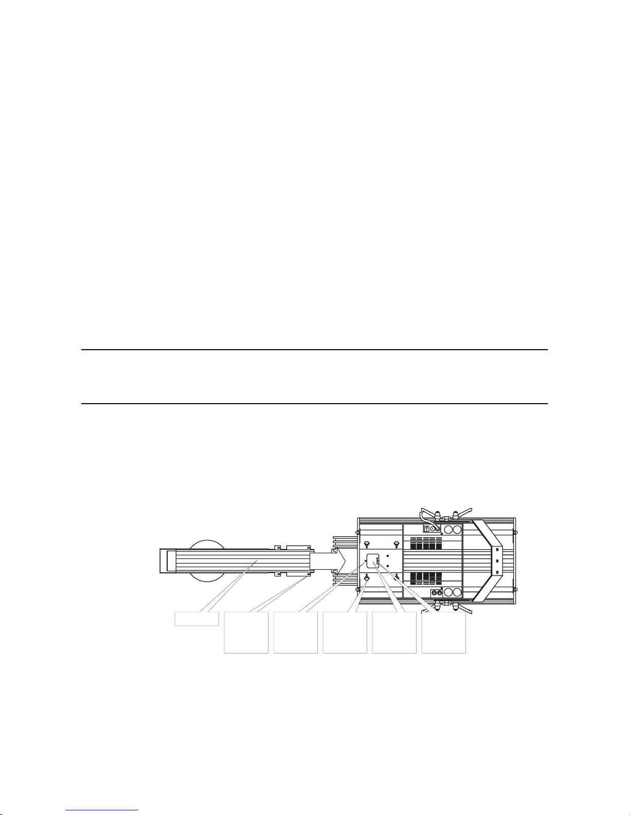
Mounting the pan/tilt unit
IMPORTANT
Never disconnect the pan and tilt cables while the PAL is under power. Doing so
will
damage the driver ICs.
This procedure is not required for units shipped from the factory in flight cases.
1.
Release the four thumbscrews located on the top front of the PAL.
2.
Attach the safety wire of the pan/tilt unit to the dedicated hole in the PAL body.
3.
Connect the pan and tilt cables from the pan/tilt unit to the terminals on the body. Ensure that the connectors are pressed firmly into place.
4.
Place the pan/tilt unit on top of the PAL so that the four securing points are right in front of the retaining
thumbscrews. Verify that the pan/tilt cable and the safety wire fit properly in the space under the pan/tilt
shaft.
5.
Slide the pan/tilt unit towards the rear of the PAL so that the securing points and the thumbscrews slide into
one another. Tighten the thumb screws.
To remove the pan/tilt unit, follow the above procedure in the reverse order.
Connectors for
pan/tilt
wires.
Pan/tilt unit. Hole for
attaching
safety
hook.
thumbscrews for
securing
pan/tilt unit.
Securing
points for
retaining
screws.
Space for
pan/tilt
cable and
safety wire.
Page 7

PAL 1200, PAL 1200 E, PAL 1200 FX User Manual 7
Removing the transport fixture
In order to protect the pan/tilt assembl y from becom ing damag ed durin g shipmen t it has been secured with black plas tic straps.
Cut and remove these plastic straps.
Fitting the mirror
1.
Release the two thumbscrews on the tilt motor.
2.
Place the mirror on the tilt motor.
3.
Tighten the two thumbscrews.
4.
Carefully remove the surface protection foil from the mirror.
Installing the lamp
WARNING!
Make sure that the fixture is isolated from the mains supply.
The PAL may be used with either the Osram HSR 1200 or the Philips MSR 1200 lamp.
1.
Remove the thre e screws that s ec ure the ac ce ss plate of the lamp socket as se mbly at the rea r of the PAL
and with-
draw the lamp socket assembly.
2.
Hold the lamp by the ceramic parts, avoiding touching the glass part with your fingers, and carefully insert it
into the lamp socket. If you accidentally touch the glass part with your fingers you must clean it thoroughly
with the cleaning cloth supplied with the lamp. You can also use a clean lint free cloth wetted with alcohol.
3.
Replace the lamp socket assembly, ensuring that the lamp locates properly into the aluminum reflector, and
tighten the Philips screws.
NOTE:
The lamp position is adjusted at the factory, however, re-adjustment may be necessary to optimize the light output
and the color uniformity with the CMY (Cyan, Mag ent a, Yellow) system. Please refer to section 8.
Fitting the mains plug
The PAL is delivered from the facto ry witho ut a plug on th e mains ca ble. You will have to fit a plug that conforms to your local
mains outlet. The double-insulated mains cable contains three wires.
1.
Connect the BROWN wire to the LIVE pin.
2.
Connect the BLUE wire to the NEUTRAL pin.
3.
Connect the YELLOW/GREEN wire to the EARTH pin.
Checking voltage and frequency settings
It is vital that both voltage and freq uency settin gs of the PAL match the local power supply. If this is not t he case, you will h ave
to rewire the fixture as described in section 8. The factory setting of voltage and frequency is printed on the serial number label
at the back of the fixture.
Rigging the PAL
You can now rig the fixture by means of its mounting bracket. The PAL has a graduated sca le on ea ch sid e of the bod y whic h
allows you to align it with other fixtures. The mountin g br ack et allo ws you to tilt the fixtu re from 70° up to 6 0° down. Use the
lever handles on the sides to lock the fixt ure into the desired angle.
Page 8
8 PAL 1200, PAL 1200 E, PAL 1200 FX User Manual
section 3
CONNECTING THE CONTROLLER
All effects in the PAL are fully DMX-512 and Martin RS-485 implemented. Control data is transmitted from the controller’s
output, via XLR data lin k cable s, to the data in put on the PAL. The data output on the PAL allows the serial data link to be con tinued to additional lights, and this way up to 32 fixtures can be connected on the same data link.
Connecting the serial link
USING THE PAL AND OTHER MARTIN LIGHTS ONLY
1.
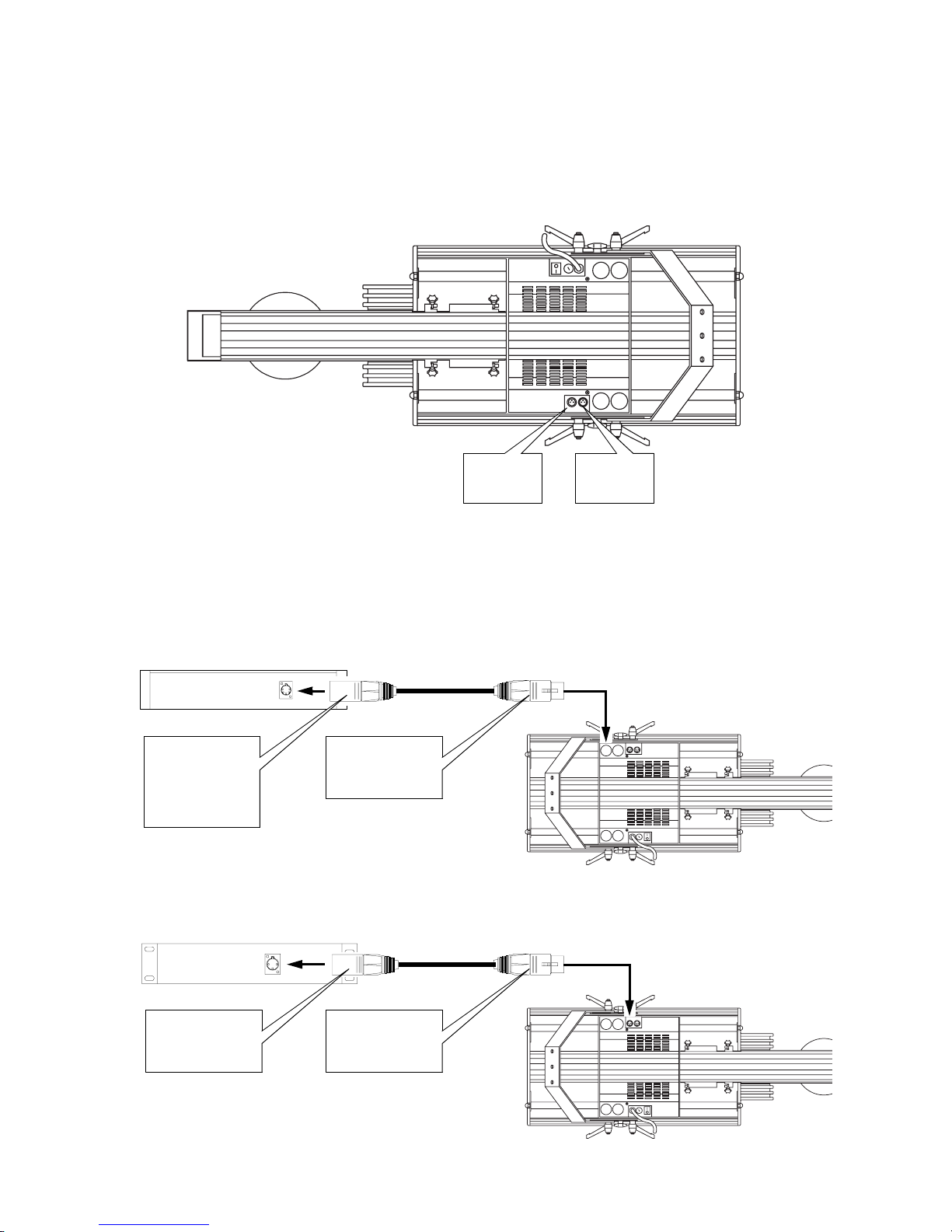
Connect the data output of your lighting controller to the data input on the PAL.
Data
output
via 3 pin
XLR female.
Data
input
via 3 pin
XLR male.
5 pin XLR male:
Pin 1: GND (screen)
Pin 2: Signal (-)
Pin 3: Signal (+)
Pin 4: N/C
Pin 5: N/C
DMX Controller
with standard 5 pin XLR output.
3 pin XLR female:
Pin 1: GND (screen)
Pin 2: Signal (+)
Pin 3: Signal (-)
Martin Co ntroller
with standard 3 pin XLR output.
3 pin XLR female:
Pin 1: GND (screen)
Pin 2: Signal (+)
Pin 3: Signal (-)
3 pin XLR male:
Pin 1: GND (screen)
Pin 2: Signal (+)
Pin 3: Signal (-)
Page 9
PAL 1200, PAL 1200 E, PAL 1200 FX User Manual 9
MARTIN CONTROLLER:
Use the XLR-XLR or DSUB-XLR cable supplied with the controller.
DMX CONTROLLER:
Most DMX controllers have 5 pin XLR sockets for data o utput. For this reason you must use a
cable that adapts from the 5 pin DMX output to the 3 pin XLR input on the PAL. The following figure shows the proper connections in such a cable (P/N 11820003). Note that the (+) and (-) signal wires are reversed between the output of the DMX
controller and the input of the PAL.
2.
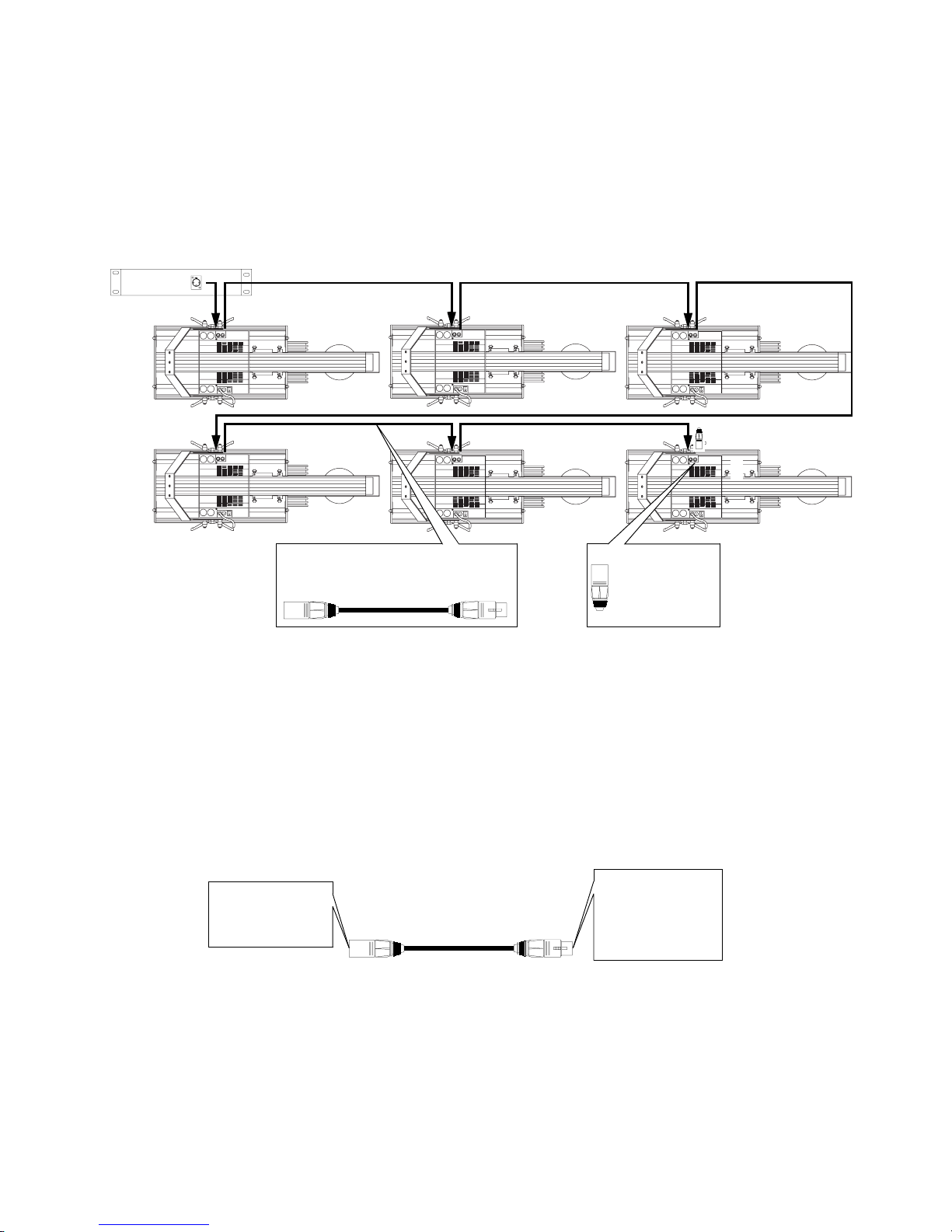
Connect the data output of the first PAL to the data input of the next using the XLR-XLR cable supplied with
the PAL.
3.
Continue the link this way, always connecting output to input (daisy-chain), until all fixtures are linked
together (max. 32 per data link).
4.
Finally, insert a male XLR termination plug in the free output socket of the last light on the link.
MARTIN CONTROLLER:
Use the 120 Ω termination plug supplied with the controller.
DMX CONTROLLER:
Use a 3 pin XLR male plug with a 120 Ω resistor between pins 2 and 3.
NOTE:
It is very important to insert the termination plug to ensure correct and error-free communication between the con-
troller and the fixtures.
INSERTING NON-MARTIN DMX LIGHTS
If you are using a DMX controller it is possible to insert non-Martin lights, using 5 pin XLRs in and out, on the link. In this
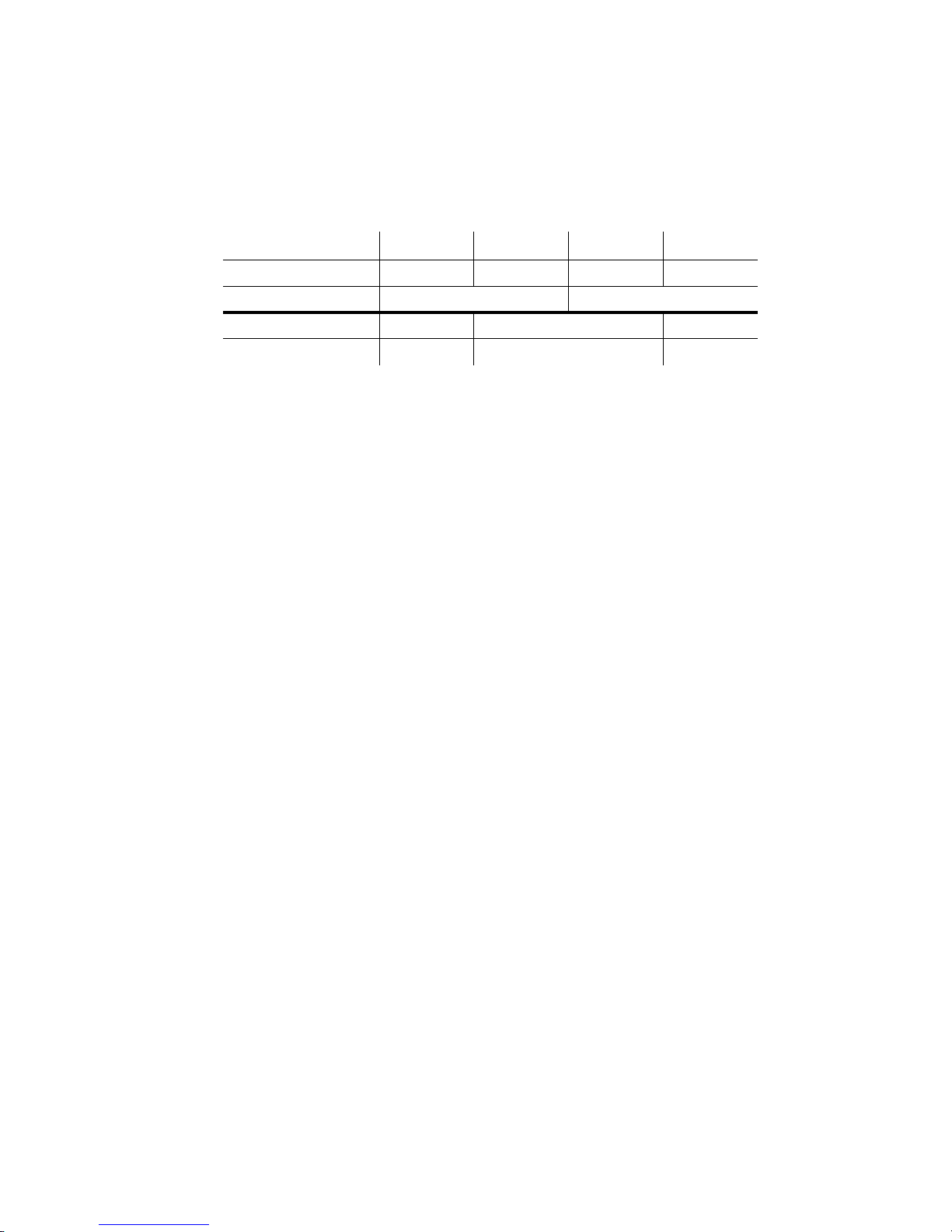
case you will need a cable that adapts from the 3 pin XLR female output on the preceding Martin light to the 5 pin XLR male
input on the next non-Martin DMX light. The connections in such a cable (P/N 11820002) are shown in the following figure.
Addressing the PAL
The control module on the left side of the PAL allows you to assign the fixture addres s, which is defined as the fi rst channel
from which the PAL responds to the controller. Depending on which DMX mode you selected, the PAL requires more or less
channels for control. E.g. , if the partic ular DM X mode re quires 22 chan nels and yo u ad dress the fix ture t o channe l 1, it wil l u se
channels 1 to 22. You must address the PAL fixtures according to your controller configura tion, or vice versa, en suring no
channels are being used by more than one fixture. If two or more fixtures of the same type share the same address they will
perform identically.
Use standard 3 pin XLR/XLR data cables to
connect the lights. Pin 1 = screen,
pin 2 = signal (+), pin 3 = signal (-).
Remember to
insert XLR
termination plug in
the last light on the
data link.
5 pin XLR female:
Pin 1 = GND (screen)
Pin 2 = signal (-)
Pin 3 = signal (+)
Pin 4 = N/C
Pin 5 = N/C
3 pin XLR male:
Pin 1 = GND (screen)
Pin 2 = signal (+)
Pin 3 = signal (-)
Martin Output to DMX Input
Page 10
10 PAL 1200, PAL 1200 E, PAL 1200 FX User Manual
1.
Switch on the PAL1200 (E)
and wait until the reset has finished (see ‘Switching On’ below).
2.
Press [menu] once to access the main menu and browse through the options, using the arrow keys, until the
display shows ‘dAdr’ or ‘Adr’ depending on whether you want to assign the fixture a DMX or Martin address,
respectively. Confirm by pressing [enter].
3.
Use the arrow keys to select the desired address and confirm by pressing [enter].
The DMX channel requireme nts ar e listed in t he foll owin g ta bl e. Th e PAL requires 2 channels when operated via a Martin RS 485 controller.
Switching on
After switching on, the PAL will index all effects and return these to their default positions. Some effects use a mechanical
indexing method causing some no ise. This noise is comp lete ly n orma l and o nly last s for a sho rt perio d o f tim e. The disp lay on
the side of the fixture will show t he software v ersions installe d in the PAL and then advance to protocol auto-detect. As soon as
data is transmitted from your controller, the PAL automatically detects whether it is a Martin RS-485 or DMX 512 controller
and responds accordingly. When this occurs the display reads “PASS.”
Operating the fixture
If you are using a Martin RS-485 controller then please refer to that controller’s manual for further operating instructions. If
you are using a DMX 512 controller then please refer to the DMX 512 protocol listed in appendix A of this manual. All
remotely controllable functions are briefly described in section 5 - ‘REMOTELY CONTROLLABLE FUNCTIONS’.
NOTE:
The P AL is fitted with a remotely operated lamp relay, allowing the lamp to be switched on and of f via the contro ller
without affecting other functions of the fixture. However, after switching on the PAL, the lamp itself remains OFF until a
‘Lamp ON’ command is sent from the controller. Any attempt to start the lamp within 4 minutes after having switched it off,
will be ignored by the lamp circuit, however, the PAL stores the instruction and automatically ignites the lamp once the 4
minute period has expired. This is to ensure a safe strike of the lamp.
When switching on the lamp, the PAL draws a surge (peak) current which may be several times the normal operating current.
For this reason, it is suggested that you program a ‘Lamp On’ sequence at t he controller, which will turn on the lamps one at a
time with an interval between each ‘Lamp On’ command of approximately 5 seconds.
DMX Mode Mode 1 Mode 2 Mode 3 Mode 4
Pan / tilt resolution 8 bit 16 bit 8 bit 16 bit
control Tracking Tracking / Vector
PAL 1200, PAL 1200 E 22 channels 24 channels 26 channels
PAL 1200 FX 16 channels. 18 channels 20 channels
Page 11

PAL 1200, PAL 1200 E, PAL 1200 FX User Manual 11
section 4
REMOTELY CONTROLLABLE FUNCTIONS
This section briefly describes the various functions that can be remotely controlled via the serial data input on the fixture.
LAMP
The PAL uses the Philips MSR 1200 or the Osram HSR 1200 lamp and is fitted with a relay that allows the lamp to be
switched on and off via the controller. After switching on the PAL, the lamp itself remains OFF until a ‘Lamp ON’ command
is sent from the controller. Any attempt to start the lamp within 4 minutes after having switched it off will be ignored by the
lamp circuit. However, the PAL stores the instruction and automatically ignites the lamp once the 4 minute pe riod ha s expire d .
When switching on the lamp, the PAL draws a surge (peak) current which may be several times the normal operating current.
For this reason, it is suggest ed that yo u pro gram a ‘La mp On’ se quence at the co ntroller, which turns o n the lam ps one at a time
with an interval between each ‘Lamp On’ command of approximately 5 seconds. This is to ensure a safe strike of the l amp.
NOTE:
To avoid accidentally switching off the lamp, the ‘Lamp Off’ feature is only supported by DMX-512 if enabled on
the control module (see secti on 6) or if cyan, magenta and yellow channels are set to a certain value (see append ix A).
MOVEMENT
The pan/tilt mirror on the PAL allows you to move the beam to any desired position within the range of 287º by 85º and micro
stepping control o f the m otors ensu res smoot h and acc urate m ovemen t at all speeds. 10 ,200 po sitions on pan and 1,50 4 positions on tilt can be achieved when using either a Martin controller or 16-bit pan/tilt resolution via DMX. Selecting the B/O
speed will blackout the fixture whilst moving the mirror.
COLOR WHEEL
The color wheel offers five easily interchangeable dichroic color filters, plus an open white position. The B/O speed will
blackout the fixture whilst changing from one color to another.
CMY - COLOR MIXING
The CMY color mixing system is based on three sets of color flags: Cyan, Magenta and Yellow. These filters can be adjusted
individually between 0 and 100%. A wide range of colors can be produced by proportionally inserting one or two of the three
color flags at the same time. Th e pre c ise c olor is de te rmine d b y the p e rcenta ge (0 to 1 00 % ) of each c olor fla g whic h is a pplie d .
Instant color changes are achieved wh en programming the color flags with a high speed. Slower speed s provide a smooth
cross-fade from one color into another. Please note that an optimized lamp adjustment is very important for perfect color uniformity across the beam.
ROTATING GOBOS
Four rotating, indexibl e gobos, tw o fixed and on e open , can be select ed. All ro tating gobo s are bi-dir ectional and can be p rogrammed to any desired or ientation. Th e B/O speed blacks ou t the fixture whilst changing th e gobo or the orien tation of the
gobo.
ROTATING EFFECTS (PAL 1200 FX)
Three rotating indexibl e gobo s/effects, on e fixe d a nd on e o pen, can b e sele cted. All ro tat ing effects are bi -dire ctiona l and ca n
be programmed to a ny orientation. The B/ O speed blacks out the fixture whilst changing gobos or orientation.
DIMMER/SHUTTER
High resolution, 0 to 100% smooth dimming is provided by the combined dimmer/shutter system. Use a high speed for dimming if you wish to open or close the dimmer/shutter instantly.
FOCUS
Motorized focus allows remote focusing at any time.
ZOOM
Motorized zoom allows you to vary the beam angle between 15 and 26º.
FRAMING SHUTTERS (PAL 1200, PAL 1200 E)
Four shutters, each individually controlled by two motors, allow you to produce almost any desired frame. In addition, the
entire frame can be swivelled +/- 22.5º from the default position.
Page 12

12 PAL 1200, PAL 1200 E, PAL 1200 FX User Manual
IRIS (PAL 1200 FX)
The beam diameter ca n be reduced from 100% to 5% using the motorized iris.
VARIABLE WASH
Inserting the wash filter produce s a wa sh-ligh t effect. The e ffect of the wash fil ter can be vari ed o ver a wide rang e depen din g
on the proportion of the filter used.
FA N
The PAL is efficiently cooled by means of its low-noise axial fans. It is possible to reduce fan speed should extremely silent
performance be required. L ow fan speed reduces the cooling of the fixture and sh ould only be used when the ambient temperature is 25°C or lower. If the temperature inside the fixture exceeds a certain level (the cut-out threshold), a built-in thermostat
automatically switches off the lamp. This situation,
which should be avoided
, may occur if the fixture is operated with low
fan speed over a long period of time in high temperatur e surroundings.
NOTE:
When switching off the lamp, the fans automatically power off after 4 minutes.
Page 13

PAL 1200, PAL 1200 E, PAL 1200 FX User Manual 13
section 5
CONTROL AND RECEIVER MODULE
The control and rec e iver module on the side of the PAL offers several useful features. You can set the fixture address, read out
lamp and fixture usage, enable special features etc. The main-menu is accessed by pressing the [menu] key and can be browsed
using the [up] and [down] keys. The menu hierarchy is shown in the following diagram, which includes the ‘SPEC’ sub menu.
Main functions
DMX 512 ADDRESS (dAdr)
Use the arrow keys to select the fixtu re address when usi ng a DMX-512 control ler and press [enter] to c onfirm or [menu] to
cancel. Either way you will return to the main menu.
MARTIN RS-485 ADDRESS (Adr)
Use the arrow keys to select the fixture address when using a Martin RS-485 controller and press [enter] to confirm or [menu]
to cancel. Either way you will return to the main menu.
PROTOCOL SET-UP (PSEt)
After switching on the PAL, it automatically detects whether the controller is transmitting DMX 512 or Martin RS-485. If a
DMX controller is detected the PAL defaults to the DMX protocol (1, 2, 3 or 4) selected in the protoco l setup (PSEt). The table
below shows the difference be tween the four avai lable DMX protocol s. If a Martin cont roller is detected the PAL automatically switches to protocol 0, which is the Martin RS-485 protocol.
Use the arrow keys to select the desired protocol and press [enter] to confir m or [menu] to cancel.
FIXTURE USAGE (Po H)
This option provides a read-out of the total number of hours the PAL has been powered on.
LAMP USAGE (LA H)
This option provides a read - o ut of t he tota l num b er of ho ur s the lam p ha s bee n used .
FIXTURE USAGE - RESETABLE (r Po)
As with the ‘Po H’ counte r, this option provides a r ead-out of th e number of ho urs that the PAL has been powered on. However, it is possible to reset this counter by keeping the [up] key pressed for approx. 5 seconds.
DMX Mode Mode 1 Mode 2 Mode 3 Mode 4
Pan / tilt resolution 8 bit 16 bit 8 bit 16 bit
control Tracking Tracking / Vector
PAL 1200, PAL 1200 E 22 channels 24 channels 26 channels
PAL 1200 FX 16 channels. 18 channels 20 channels
rES
on OFF
dISP
on OFF
Auto
on OFF
LoFF
on OFF
dPr2
St 1 St99
SP 1
St 1 St99
SP16dnLd
SUAP n SU
PAtI
Inv nIn v
tILt
Inv nInv
PAn
SPEC Po H LA H r Po r LA
0-4
PSEt
1-31
Adr
1-512
dAdr
Fixture Address
...............
dFSE
0-255
d Ad
0-255
c Ad
0-255
n Ad
0-255
y AddFOF
SureSure
Page 14

14 PAL 1200, PAL 1200 E, PAL 1200 FX User Manual
LAMP USAGE - RESETABLE (r LA)
As with the ‘La H’ counter, this option provides a read -out of the number of hours the lamp has been powered on. However, it
is possible to reset this counter by keeping the [up] key pressed for approx. 5 seconds. Use this facility to reset the counter
whenever replacing the lamp to keep track of lamp life.
Special functions (SPEC)
Selecting th is fu nction p resen ts yo u with a sub -menu o f speci al fu nctio ns. As in th e mai n-menu , you c an br owse th rough the
options and select the one displayed by pressing [enter].
AUTOMATIC BLACKOUT OF DISPLAY (dISP)
Use the arrow keys to toggle between ‘on’ and ‘off’. Select ‘on’ by pressing [enter], if you wish the display to blackout 2 minutes after the last press of any of the keys, in order to avoid audience distraction. Otherwise, select ‘off’. The blackout function
will not affect the appearance of error and information messages.
PROTOCOL AUTO-DETECT (Auto)
This option can be used to di sa ble t he pro toco l aut o-d etect func tio n whe n switc hi ng on the fixtu re. Use the a rrow key s to toggle between on and off. Select ‘on’, by pressing [enter], if you wish the protocol auto-detect function to be enabled after
switching on the fixture, and ‘off’ if you wish to disable this function.
If protocol auto-detect is disabled (Auto = OFF) the PAL defaults to the protocol selected in the pr otocol set-up (0 = Martin, 1
= DMX1, 2 = DMX2, 3 = DMX3 or 4 = DMX4).
PAN INVERT (PAn)
This function allows you to invert the pan movement (DMX protocol only). Use the arrow keys to toggle between ‘Inu’ for
inverted pan, and ‘nInu’ for non inverted and press [enter] to confirm or [menu] to cancel. Either way you will return to the
SPEC-menu.
TILT INVERT (tiLt)
This function allows you to invert the tilt movement (DMX Protocol only). Use the arrow keys to toggle between ‘Inu’ for
inverted tilt, and ‘nInu’ for non inverted and press [enter] to confirm or [menu] to cancel. Either way you will return to the
SPEC-menu.
NOTE:
If using the Martin 3032 Controller, pan and tilt invert can be enabled from the link configuration menu.
PAN AND TILT SWAP (PAtI)
This function allows you to swap the pan and tilt channels in DMX. Use the arrow keys to toggle between ‘SUAP’ for
swapped protocols and ‘n SU’ for non swapp ed and pre ss [ente r] to confirm or [men u] to cance l. Eith er way yo u will ret urn to
the SPEC-menu.
DOWNLOAD (dnLd)
For factory programming only - do not use.
RESET OF RECEIVER MODULE (rES)
Pressing [enter] on this option resets the receiver CPU and activates the protocol auto-detect function.
LAMP OFF VIA DMX (LoFF)
This option allows you to enable/disable the ‘Lamp Off’ function via DMX. Use the arrow keys to toggle between ‘on’ and
‘off’ and select ‘on’ by pressing [enter] if you wish to enabl e this feature and ‘off’ if you wish to disable the feature.
SPECIAL DMX PROTOCOL (dPr2)
This option applies for the PAL 1200 and PAL 120 0 E on ly - not the PAL 1200 FX - and should be enabled only when operat ed
by
MA Lighting’s “Scancommander
”. The ‘dPr2’ option reconfigures the DMX channel configuration, thus enabling the
Scan-
commander
to control the PAL 1200 as if it were two individua l fixt ure s (co nsult ap pend ix A for the DMX chan nel c on figu ra tion). The protocol may be suitable for other lighting controllers with limitations in terms of the number of DMX channels
available per fixt ure.
Use the arrow keys to toggle bet w een ‘on’ and ‘off’ and select ‘on’ by pressing [enter] to enable ‘dPr 2’.
Page 15

PAL 1200, PAL 1200 E, PAL 1200 FX User Manual 15
CALIBRATION OF DIMMER AND COLOR MIXING (d Ad, c Ad, n Ad, y Ad)
This function allows you to calibra te the d immer a nd c olor m ixi ng syste m s, th us allo wing seve ral PALs to dim out at precisely
the same value and prod uce equal colors when se t to the same values. The pro cedure is quite simpl e and the same for both
dimmer and color mixing. First, line up the PALs you wish to calibrate. Then select the relevant calibration parameter (d Ad =
dimmer, c Ad = cyan , n Ad = magenta , y Ad = yellow) and use the arrow ke ys to adj ust each ind ividu al fixtur e until they all
produce the same output (the values can be set between 1 and 255). Finally, store the calibration by pressing [enter].
DEFAULT/CLEAR SETTINGS (dFSE)
This function will restore all receiver module settings (such as pan/tilt swap, pan invert, tilt invert etc.) to the factory default
setting. The default function needs to be confirmed by pressing [enter] when the display reads "SurE" (sure ?). Once all settings are reset to default, the display shows "donE" (done). NOTE: This function will not clear calibrations of dimmer, cyan,
magenta and yellow.
DEFAULT/CLEAR CALIBRATIONS
This function clears the calibrations of dimmer, cyan, magenta and yellow. The default function needs to be confirmed by
pressing [enter] when the display reads "SurE" (sure ?). Once all registers are cleared, the display sh ows "donE" (done).
SPECIAL SEQUENCES (SP 1 to SP20)
Up to 20 special service and adjustment sequences are available. These are mainly used for servicing purposes. After selecting
a sequence, use the arrow keys to step through the seque nce. Press [menu] twice to return to the SPEC-menu. Pl ease consult
appendix C for a full descr iption of the sequences .
Error and information messages
The following error messages may appear on the display: Please consult appendix E for full information.
HOT MESSAGE (Hot)
This message appears if you attempt restrik e the lamp within 4 m inu tes a fte r havi ng swi tched i t off. The PAL stores the ‘Lamp
On’ instruction and re-ignites the lamp once the 4 mi nute period has expired.
Auto / address and PASS
After having switched on the PAL it will default to protocol auto-detect mode which is indicated by the display switching
between ‘Auto’ and th e previously used fixtur e address. The message ‘PASS’ appears for about half a second when the protocol version (Martin or DMX) has been detected and communication between t he electronics modules ve rif ied.
Display Read-out Message
LErr Lamp error
ErAb A/B module error
ErrA A module error
ErrB B module error
ShEr Short error
TErr Time keeper error
Page 16

16 PAL 1200, PAL 1200 E, PAL 1200 FX User Manual
section 6
REPLACING GOBOS AND COLOR FILTERS
WARNING!
Before attempting any of the following, ensure that the fixture is isolated from mains.
COLOR FILTERS
The P AL uses 52 mm square dichroic color filters, all easily interchangeable. You can also fit D-size gobos on the color wheel.
To hold these in place you will need a specially made metal frame (P/N 17320130)
1.
Access and remove the color/gobo module as described on page 19.
2.
Turn the color wheel until the color filter you wish to replace becomes accessible. The color filter is held in
place by a spring. Remove the spring by pressing the two ends together, then remove the color filter.
3.
Insert the new color filter and replace the spring. .
GOBO INSTALLATION
The PAL uses standard D-size metal gobos or glass gobos with overall diameter between 49.5 mm and 50.0 m. Both types are
easily interchangeable. Custom made glass gobos should have the same image size as a standard D-size gobo, i .e. Ø 44 mm.
1.
Access and remove the color/gobo module as described on page 19.
2.
Turn the gobo wheel until the gobo you wish to replace becomes accessible.
3.
The gobo is held in place by a spring. Remove this spring by pressing the two ends together, then remove
the gobo.
4.
Insert the new gobo and replace the spring.
Page 17

PAL 1200, PAL 1200 E, PAL 1200 FX User Manual 17
GOBO ORIENTATION
As a general rule, install gobos with the most reflective side towards the lamp in order to minimize heat buildup.
Heat buildup is typically not a problem when installing coated glass gobos in the PAL. Chrome-coated glass gobos, however,
should be installed with t he coated surface facing the lamp if the optional condenser lens is installe d.
Otherwise, glass gobos may be inserted however necessary to achieve correct projection or best focus. On the color/gobo module, best focus is achieved when the coate d side faces the mirror. Gobos on the effect wheel (PAL 1200 FX), however will
morph better if they are installed with the coated side towards the lamp. Correct projection is achieved when the true image
faces the mirror.
Textured glass gobos must be installed with the smooth side facing the lamp.
Logos and other images should be installed with the image facing the mirror.
Coated Glass Gobos
When an object is held up to the
uncoated side, there is a space between
the object and its reflection. The edge of
the gobo can be seen when looking
through the uncoated side.
Coated sideUncoated side
When an object is held up to the
coated side, there is no space
between the object and its reflection.
The edge of the gobo cannot be seen
when looking through the coated side.
Textured side towards mirror
Structured Glass Gobos
Smooth side towards lamp
Image Gobos
Correct image towards mirrorReversed image towards lamp
Page 18

18 PAL 1200, PAL 1200 E, PAL 1200 FX User Manual
DEFAULT GOBO LAYOUT
PAL 1200 FX PAL 1200
Page 19

PAL 1200, PAL 1200 E, PAL 1200 FX User Manual 19
section 7
MAINTENANCE AND BASIC SERVICE
With regular maintenance you can ensure that the PAL performs at its optimum without interruptions. Dirty lenses and filters
reduce the brigh tness and diffuse th e proje cted image . Cooli ng fans c over ed by dust may c ause ove rheati ng, t hus cau sing th e
thermostat to cut out the lamp intermittently. This section not only takes you through the general maintenance procedures, but
also describes some basic service operati ons which you can carry out yourself.
IMPORTANT!
Read the following descriptions carefully before attempting to make any adjustments
whatsoe v er. If y ou do no t f eel comp letely c ompetent to m ak e the correct ions y ou shou ld
consult qualified service personnel for assistance.
Removing and replacing modules
The PAL has been designed with ease of servicing and maintenance in mind and is constructed in a totally modular fashion. If
there is a probl e m in any particular section, or you want t o put in your own custom gobos or color filters, or you need to clea n
parts of the fixture, it is a simple op eration to remove and replace any modul e.
WARNING!
Ensure that th e fixture is disconnected from mains power be fore proc eeding.
REMOVING A MODULE
1.
The bottom cover is secured by means of four 1/4-turn fasteners. Release the cover by turning the fasteners
counter clockwise, and then remove the cover downwards, thus revealing the inside of the fixture (see diagram on
next page). As you remove the cover you will notice that a safety wire secures it to the chassis. You may leave the
cover hanging on the safety wire while servicing the fixture.
2.
Locate the module that you wish to remove from the fixture. You will see that there are some PCB connectors connecting the module to a wiring loom. Remove these connectors taking care to note the location and
direction of each one.
3.
On each side of every module there is a thumbscrew. Unscrew these and carefully pull the module straight
out of the fixture.
Color/gobo module
CMY moduleFraming module (PAL 1200, PAL 1200 E)
Effects module (PA L 1200 FX)
Zoom/focus/frost module
Dimmer module
Lamp socket
assembly
Page 20

20 PAL 1200, PAL 1200 E, PAL 1200 FX User Manual
REPLACING A MODULE
To replace a module simply reverse the steps a bov e. M ake sure t hat the m odule i s st raight and loca tes p rope rly: the re are two
pins on the top of the module that fit in holes in the inner casing.
PAL 1200 FX note
: The PAL 1200 FX uses the same wiring harness as the PAL 1200 so that either unit may be converted to
the other. Connect the wires to the effect module as follows.
Cleaning the optical path
Be very careful when cleaning the optical components (color filters, glass gobos, lenses, reflector and mirror). The colored surface on the filters is achieved by means of special multi-layer coatings and even small scratches in these might be visible. Use
only a clean, soft and lint-free c lot h like the one s us ed for cl eani ng cam era l enses. You may need to wet the cloth with a no naggressive glass cleaning liquid if the filters or lenses are greasy. It may also be necessary to clean the gobos and shutter blades
and special care should be taken not to damage these fragi le parts.
DIMMER MODULE
Remove the dimmer module and clean the heat reflection filter on both sides.
CMY MODULE
Remove the CMY module and carefully clean:
• All six color filters.
• The diffusion filter (if mounted).
COLOR/GOBO MODULE
Remove the color/gobo modu le and carefully clean:
• The color filters. The color filters can easily be removed from the color wheel to ease cleaning.
• The gobos. If you have used the gobo indexing facility in your lighting programs then do not remove the gobos from the wheel
whilst cleaning these. Otherwise, you will need to reprogram all scenes with indexed gobos, if you are not able to replace the
gobo in exactly the same position.
• The condenser lens (if mounted).
PROFILE MODULE
Remove the module and carefully clean all four profile shutters.
FOCUS/ZOOM MODULE
It is recommended to leave the focus /zoom module in the fixture when cl eaning the lenses.
PAN/TILT MIRROR
The PAL uses a front coated mirror to ensure a sharp and un-d istorted image. Clean the refl ective side of the mirror using a
soft, lint-free cloth wetted with a non-aggressive glass cleaner.
FA N S
To ensure proper cooling of the fixture it’s important that the fans are free of dust. Clean the fans if the air flow seams to be
reduced. The fan grill at the rear end of the fixture can be removed by unscrewing the 3 Phillips screws that secure it to the
back plate.
Wire Effects module terminal (PAL 1200 FX)
KN1B GOBO
K-WHEEL R-GOBO
KN3B IRIS
KN4A unlabeled right connector
KN1A, KN2A, KN3A, KN2B unlabeled left connectors (any order)
KN4B Do not connect
Page 21

PAL 1200, PAL 1200 E, PAL 1200 FX User Manual 21
Replacing the lamp
Discharge lamps operate under high p ressure. As the lam p ages t he glass env elope b ecom es more frag ile and the risk of lam p
explosion increases. Therefore it is strongly recom mended that the lamp be replaced before its rated averag e life has been
exceeded by 25%. The max imum recommended service life for th e Philips MSR 1200 and the Osram HSR 1 200 lamps is
therefore 1000 hours. The procedure for installing the lamp is described in section 3 - ‘BASIC INSTALLATION’.
The position of the lamp-holder may need to be re-adjusted to ensure optimum performance when the PAL is installed in its
permanent site. The adjustment procedure follows.
Optimizing the lamp alignment
After lamp replacement it may be necessary to optimize the lamp adjustment. Thanks to some built-in sequences this adjustment can be made withou t conne cting a cont roller to the PAL. However, should you prefer to do the ad justme nt usi ng a co ntroller you may do that as well.
1.
Switch on the PAL and wait until the reset has finished.
2.
Via the control module select sequence ‘SP 2’, thus igniting the lamp. Before you continue with the next step
you should wait approx. 5 minutes until the lamp has reached full brightness.
3.
Select sequence ‘SP 4’, step ‘St 1’. This leaves you with an open white gobo focused to approx. 5 meters.
4.
Carefully move the mirror by hand so that the image is projected onto a flat surface.
5.
On the back of the fixture there are three lamp adjustment screws (see following diagram). Tur ning these
clockwise will pull the lamp towards the rear of the lamp housing, and vice versa. Center the hot-spot (the
brightest part of the image) by using the three adjustment screws. When only using one screw at a time you
will drag the hot-spot diagonally across the projected image. If you are using the standard optical configuration with diffusion filter, and without the condenser lens mounted, there is practically no hot-spot. In that
case adjust the lamp until you achieve an even distribution of the light all over the image.
6.
If you are not satisfied with the light output you can try to adjust the lamp further by turning all three adjustment screws a quarter turn clockwise, making sure that the hot-spot remains centered. If the result is an
improvement then repeat this procedure until there is no more improvement. If the light-output is reduced
then turn the adjustment screws a quarter turn counter clockwise and observe the result. Proceed this way
as long as the result is an improvement.
7.
Select step ‘St 2’ from the currently selected sequence (SP 4) thus inserting all three sets of CMY flags into
the beam. Now, make slight adjustments to the screws until the PAL projects an almost uniform color across
the entire image. Please note that if your are using an optical configuration without the diffusion filter and/or
with the condenser lens fitted, you will not be able achieve a completely uniform color projection.
Page 22

22 PAL 1200, PAL 1200 E, PAL 1200 FX User Manual
Voltage and frequency settings
The PAL has five voltage settings and , excep t for the P AL 1200 E, two frequency settings (50 or 60 Hz) that can be selected in
any combination. To ensure safe and proper operation, it is vital that those settings match the local power supply. The follow-
ing table lists the correct voltage settings according to the mains supply.
WARNING!
Ensure that th e fixture is disconnected from mains power be fore proc eeding.
1.
Remove the two Phillips screws which secure the small cover over the voltage and frequency terminals at the rear
end of the fixture.
2.
Connect the brown wire labelled ‘V’ to the correct voltage terminal (see the table above).
3.
(PAL 1200, PAL 1200 FX) Connect the brown wire labelled ‘F’ to the correct frequency terminal.
4.
Replace and secure the small cover again.
Regenerating malfunctioning lamps
Discharge lamps may not strike if the mains voltage applied to the fixture is too low (this could happen in areas with substantial voltage fluctuations). Instead of striking, the lamp burns with a faint blue arc, and after a period of time it becomes black
on the inside. When this happens the lamp will refuse to strike even when mains voltage returns to normal level. However, in
this situation it is possible to regenerate the lamp following the instructions below:
WARNING!
Ensure that th e fixture is disconnected from mains power be fore proc eeding.
1.
Remove the two Phillips screws which secure the small cover over the voltage and frequency terminals on the rear
end of the PAL (see previous section).
Magnetic ballast: PAL 1200, PAL 1200 FX Electronic ballast: PAL 1200 E
Local AC voltage Voltage setting Local AC voltage Voltage setting
95 - 110 V 100 V 95 - 110 V 100 V
110 - 130 V 120 V 110 - 130 V 120 V
200 - 220 V 210 V 207 - 225 V 218 V
220 - 240 V 230 V 225 - 240 V 230 V
240 - 260 V 250 V 240 - 260 V 250 V
Remove this lid to
access the
voltage and
frequency
terminals.
Page 23

PAL 1200, PAL 1200 E, PAL 1200 FX User Manual 23
2.
Locate the brown wire labelled ‘V’. If this wire is connected to the 120V terminal then move it to the 100V
terminal. If it is connected to the 230V or the 250V terminal then move it to the 210V or 230V terminal,
respectively.
3.
Switch ON and send a ‘Lamp On’ command to the fixture. If the lamp strikes let it burn at this voltage for
approximately 5 minutes and then switch it off again.
4.
The lamp will now be clear on the inside and ready to re-use at the normal voltage. Disconnect the fixture
from the mains and re-connect the brown wire to the terminal where it was before.
5.
Secure the cover over the voltage terminals before operating the fixture as normal.
If the lamp failed to start, then contact your lo cal Martin dealer for assistance.
Reconfiguring the optical path
The optical system in the PAL ca n be confi gured to in crease light out put or el iminate th e ho t-spot. T he followin g table lists the
four different configurations that can be achi eved. The first (#1) is the factory default configurati on.
You may remove or fit the condenser lens and diffusion filter in any combination you wish to obtain the desired performance.
The condenser kit is available from your Martin dealer as P/N 91610004. The diffusion filter is mounted on the CMY module
and the condenser lens on the col or/ gobo module.
Martin also provides an optional narrow (10.5º to 14º) and wide angle (20º to 36º) lens.
Accessing the electronics section
By removing the top cover from the PAL you will gain access to the printed circuit boards (PCBs). Please follow the instruction below.
WARNING!
Ensure that th e fixture is disconnected from mains power be fore proc eeding.
CAUTION!
The PCBs contain compo nents wh ich are sensitive to electrosta tic di scharges . To a void
damaging any components, always ensure that you touch the ground terminal before,
and when, removing the PCBs or any component (CPU / EPROM) from a PCB.
Optical configuration
#1 #2 #3 #4
Hot-spot none some little evident
Light output 100% 138% 130% 163%
CMY uniformity perfect good acceptable acceptable
Condenser lens no yes no yes
Diffusion filter yes yes no no
B-section PCB
A-section PCB
Receiver Module
Page 24

24 PAL 1200, PAL 1200 E, PAL 1200 FX User Manual
1.
Remove the two Phillips screws on the sides and the two on the top and then lift off the cover. You can now access
the A and B-section PCBs.
2.
To access the receiver module (see drawing above) you will first have to remove the four Phillips screws
which secure it to the side panel of the fixture, and then carefully lift it upwards.
Replacing fuses
The PAL has 7 fuses - one primar y and 6 secondary.
WARNING!
Ensure that th e fixture is disconnected from mains power be fore proc eeding.
MAINS SECTION
The primary fuse is located next to the mains-input cable and can be accessed by removing the fuse holder cap. The primary
fuse is a T 20 A - 6.3 x 32 mm.
RECEIVER MODULE
There are two secondary fuses located on the receiver PCB as per the following diagram.
A-SECTION PCB / B-SECTION PCB
The A and B-section PCBs both have two secondary fuses located as per the following diagram.
Updating the software
It is possible to upgrade the software (EPROMs and CPU ) i n your PAL, s ho uld new features h a ve become availa ble since you r
purchase.
ORDERING SOFTWARE UPDATES
Upgrade software c an be s upplied b y your Ma rtin de aler, or, if you have the equ ipment t o erase and program EPROMs, you
can download the latest version of software from our Internet web site at http://www.martin.dk.
CPU software can be supplied only by your Martin dealer.
Please check with you r Martin de aler, whether or no t the parti cular soft ware upgra de require s any m echanica l change s to the
PAL.
F201: T 1A
F202: T 0.315A
F201: T 3.15A
F211: T 6.3A
Page 25

PAL 1200, PAL 1200 E, PAL 1200 FX User Manual 25
UPDATING A/B SECTION SOFTWARE (EPROM)
Having accessed the A and B-section PCBs , as described earlier in this section, you can now repla ce the EPROMs. Please follow the instruction below.
WARNING!
Ensure that th e fixture is disconnected from mains power be fore proc eeding.
CAUTION!
To avoid damaging the EPROM by electrostatic discharge you should touch the heat
sink on the PCB (GND) before, and when, removing or inserting the EPROM.
1.
On the A/B section PCBs remove the existing EPROM (IC102).
2.
Place the new EPROM in the IC socket, ensuring that all pins enter the socket correctly, and that the
EPROM is correctly oriented. Then press it firmly into the socket.
UPDATING THE RECEIVER MODULE
Having accessed the receiver module PCB, as described earlier in this section, you can now replace the CPU. Please follow the
instruction below.
WARNING!
Ensure that th e fixture is disconnected from mains power be fore proc eeding.
CAUTION!
To avoid damaging the CPU by electrostatic discharge you should touch casing of the
x-tal (GND) before, and when, removing or inserting the CPU.
1.
On the PCB(s) remove the existing CPU (IC101).
2.
Place the new CPU in the IC socket, ensuring that all pins enter the socket correctly, and that the CPU is
correctly oriented. Then press it firmly into the socket.
Heat sink
EPROM (IC102)
CPU (IC 101)
X-tal casing (GND)
Page 26

26 PAL 1200, PAL 1200 E, PAL 1200 FX User Manual
Adjusting the mirror dampers
Re-adjustment of the pan and tilt dampers may be necessary after excessive use if the movement has become jerky at certain
speeds. Adjustment is quite simple and can be carried out without need of any special tools.
1.
Loosen both of the dampers, until the spring-loaded plastic pin is no longer touching the motor.
2.
Using a controller, turn on the lamp and adjust the open gobo to a sharp focus.
3.
Still using the controller, move the mirror from side to side at a slow speed and watch the beam movement.
Tighten the pan damper until the smoothness of the mirror movement is affected and it becomes more
‘twitchy’. At this point you should turn the dampers slightly back so that you restore the full smoothness of
the mirror movement.
4.
Similarly, adjust the tilt damper.
NOTE:
If the dampers are set to a position that is too loose you will find that the mirror may lose steps when running at
higher speeds. If the dampers are set to a position that is too tight you will find that it will affect the smoothness of the mirror
movement at lower speeds.
Tilt damper
Pan Damper
Page 27

PAL 1200, PAL 1200 E, PAL 1200 FX User Manual 27
appendix a
DMX PROTOCOL
All features in the PAL are fully DMX implemente d. When operating via DMX you can choose between the four modes listed
in the table below. ‘Tra c king ’ mode m ean s th at sp eed o f move m e nt i s de te rmine d by the slo pe (c ha n ge in DMX va lu e pe r tim e
unit) generated by the DMX controller - the mirror is tracking this slope. When working in vector mode the speed is determined by a speed value set on a separate DMX channel. This channel also allows you to enable tracking mode instead. Tracking and Vector modes not only apply for mirror movement, but for all effects where the speed i s variable.
Each DMX channel in the PAL is used to provide several different functions depending on where it is set within 0-255 increments. The functions are described in the DMX protocol listed on the following pages.
DMX Mode Mode 1 Mode 2 Mode 3 Mode 4
Pan / tilt resolution 8 bit 16 bit 8 bit 16 bit
control Tracking Tracking / Vector
PAL 1200, PAL 1200 E 22 channels 24 channels 26 channels
PAL 1200 FX 16 channels. 18 channels 20 channels
DMX channel
PAL 1200 FX
DMX channel
PAL 1200, PAL 1200 E
Value FunctionM1 M2 M3 M4 M1 M2 M3 M4
1
Note:
Lamp Off will only take eff ect
if ‘SPEC’/’LoFF’ is set to
‘On’, or if ‘SPEC’/’LoFF’ set
to ‘OFF’ and all Cyan,
Magenta and Yellow flags
set between 230 and 232.
1
(10 with ‘dPr2’ = On)
Note:
Lamp Off will only take eff ect
if ‘SPEC’/’LoFF’ is set to
‘On’, or if ‘SPEC’/’LoFF’ set
to ‘OFF’ and all Cyan,
Magenta and Yellow flags
set between 230 and 232.
0 - 49
50 - 177
178 - 187
188 - 197
198 - 207
208 - 217
218 - 227
228 - 237
238 - 247
248 - 255
Strobe, Fan, Reset Fixture, Lamp ON/OFF
No function
Strobe on (Fast Æ Slow)
No function
Fan Low
No function
Reset Fixture
No function
Lamp ON (Power ON)
No function
Lamp OFF (Power OFF)
2
2
(11 with ‘dPr2’ = ‘On’) 0 - 255
Intensity
0 Æ 100%
-
3
(1 with ‘dPr2’ = ‘On’) 0 - 255
Profile shutter 1a
Open Æ Closed
-
4
(2 with ‘dPr2’ = ‘On’) 0 - 255
Profile shutter 1b
Open Æ Closed
-
5
(3 with ‘dPr2’ = ‘On’) 0 - 255
Profile shutter 2a
Open Æ Closed
-
6
(4 with ‘dPr2’ = ‘On’) 0 - 255
Profile shutter 2b
Open Æ Closed
-
7
(5 with ‘dPr2’ = ‘On’) 0 - 255
Profile shutter 3a
Open Æ Closed
-
8
(6 with ‘dPr2’ = ‘On’) 0 - 255
Profile shutter 3b
Open Æ Closed
-
9
(7 with ‘dPr2’ = ‘On’) 0 - 255
Profile shutter 4a
Open Æ Closed
-
10
(8 with ‘dPr2’ = ‘On’) 0 - 255
Profile shutter 4b
Open Æ Closed
-
11
(9 with ‘dPr2’ = ‘On’) 0 - 255
Profile orientation
22.6° CCW Æ 22.4° CW (128 = Neutral)
312
0-255
Cyan
White Æ Cyan
413
0-255
Magenta
White Æ Magenta
514
0-255
Yellow
White Æ Yellow
Page 28

28 PAL 1200, PAL 1200 E, PAL 1200 FX User Manual
615
0
‚
33
‚
66
‚
99
‚
132
‚
167
168 - 181
182 - 195
196 - 209
210 - 223
224 - 237
238 - 255
Colors
All positions (tracking)
White
‚
Color 1
‚
Color 2
‚
Color 3
‚
Color 4
‚
Color5
Fixed colors
Color 5
Color 4
Color 3
Color 2
Color 1
White
7
Note:
Index and continuous rota-
tion parameters are pro-
grammed
on channel 8.
16
Note:
Index and continuous rota-
tion parameters are pro-
grammed
on channel 17.
0 - 22
23 - 45
46 - 68
69 - 91
92 - 114
115 - 137
138 - 160
161 - 183
184 - 206
207 - 229
230 - 255
Rotating Gobo selection
Open Gobo
Gobo 1 - Indexed
Gobo 2 - Indexed
Gobo 3 - Fixed
Gobo 4 - Indexed
Gobo 5 - Indexed
Gobo 5 - Rotation
Gobo 4 - Rotation
Gobo 3 - Fixed
Gobo 2 - Rotation
Gobo 1 - Rotation
8
Note:
Gobo selection is pro-
grammed on channel 7.
17
Note:
Gobo selection is pro-
grammed on channel 16.
0 - 126
127
128 - 255
0 - 2
3 - 127
128 - 254
253 - 255
Rotating Gobo Index
Index CW
Default Index
Index CCW
Gobo Rotation
Static
CCW fast Æ slow
CW slow Æ fast
Static
9
Note:
Index and continuous rota-
tion parameters are pro-
grammed
on channel 10.
-
0 - 22
23 - 45
46 - 68
69 - 91
92 - 114
115 - 137
138 - 160
161 - 183
184 - 206
207 - 229
230 - 255
Rotating Effect selection
Open
Effect 1 - Indexed
Effect 2 - Fixed
Effect 3 - Indexed
Effect 4 - Fixed
Effect 5 - Indexed
Effect 5 - Rotation
Effect 4 - Fixed
Effect 3 - Rotation
Effect 2 - Fixed
Effect 1 - Rotation
DMX channel
PAL 1200 FX
DMX channel
PAL 1200, PAL 1200 E
Value FunctionM1 M2 M3 M4 M1 M2 M3 M4
Page 29

PAL 1200, PAL 1200 E, PAL 1200 FX User Manual 29
10
Note:
Effect selection is pro-
grammed on channel 8
-
0 - 126
127
128 - 255
0 - 2
3 - 127
128 - 254
253 - 255
Rotating Effect Index
Index CW
Default Index
Index CCW
Effect Rotation
Static
CCW fast Æ slow
CW slow Æ fast
Static
11 18
0 - 255
Focus
Near Æ Far Focus
12 19
0 - 255
Zoom
Wide Æ Narrow
13 -
0-255
Iris
Open Æ Close
14 20
0 - 255
Variable Frost
Full OFF Æ Full ON
15 - 15 - 21 - 21 -
0 - 255
Pan
Max Left Æ Max Right (127 = Neutral)
16 - 16 - 22 - 22 -
0 - 255
Tilt
Max Up Æ Max Down (127 = Neutral)
-15-15-21-21
0 - 255
Pan MSB (Coarse)
Max Left Æ Max Right (127 = Neutral)
-16-16-22-22
0 - 255
Pan LSB (Fine)
Max Left Æ Max Right (127 = Neutral)
-17-17-23-23
0 - 255
Tilt MSB (Coarse)
Max Up Æ Max Down (127 = Neutral)
-18-18-24-24
0 - 255
Tilt LSB (Fine)
Max Up Æ Max Down (127 = Neutral)
- - 17 19 - - 23 25
0 - 2
3 - 251
252 - 255
Speed Control: Pan and Tilt
Trackin g
Speed Fast Æ Slow
Blackout while moving
- - 18 20 - - 24 26
0 - 2
3 - 251
252 - 255
0 - 2
3 - 251
252 - 255
0 - 251
252 - 255
Speed Control: Cyan, Magenta, Yellow, Focus , Zoom,
Frost, Dimmer, Profile Shutters
Trackin g
Speed Fast Æ Slow
Fast speed
Color, Gobo Indexing, Rotating Effect Indexing
Trackin g
Speed Fast Æ Slow
Blackout while moving
Gobo Change, Effect Change
Shutter open while moving
Blackout while moving
DMX channel
PAL 1200 FX
DMX channel
PAL 1200, PAL 1200 E
Value FunctionM1 M2 M3 M4 M1 M2 M3 M4
Page 30

30 PAL 1200, PAL 1200 E, PAL 1200 FX User Manual
appendix b
TECHNICAL SPECIFICATIONS
Physical
• Length..................................................................................................................................................................1331 mm (52.4 in.)
• Width......................................................................................................................................................................436 mm (17.2 in.)
• Height.....................................................................................................................................................................372 mm (14.6 in.)
• Weight (PAL 1200, PAL 1200 FX).............................................................................................................................61 kg (135 lbs)
• Weight (PAL 1200 E)..................................................................................................................................................55 kg (121 lbs)
Lamp
• Philips MSR 1200........................................... ......................... .......................... ...........................................750 h, 6000K, 92 lm/W
• Osram HSR 1200..........................................................................................................................................800 h, 6000K, 92 lm/W
Per form anc e
• Light output, + diffuser - condenser (standard)..............................................................................................................9800 lumens
• Light output, + diffuser + condenser...........................................................................................................................13,500 lumens
• Light output, - diffuser - condenser.............................................................................................................................12,700 lumens
• Light output, - diffuser + condenser ............................................................................................................................16,000 lumens
Gobos
• Size (metal)............................... ......................... .......................... ......................... ................................................... ........................D
• Size (glass)......................... ... .......................... ......................... .......................... .......... 50 mm +0/-0.3 mm (1.968 in. +0/-0.012 in.)
• Maximum image diameter......................................... ... .... ......................... .......................... ....................................................40 mm
• Glass type..................................................................................................................................high temperature Borofloat or better
• Coating ..................................... ......................... ........................chrome, enhanced aluminum recommended if condenser instal led
Thermal
• Maximum ambient temperature (Ta)........................................................................................................................... 40° C (104° F)
• Maximum surface temperature....................... ......................... .......................... .........................................................80° C (176° F)
Control and programming
• Data pinout..........................................................................................................................pin 1 shield, pin 2 hot (+), pin 3 cold (-)
• Receiver ............................................................................................................................... ... .... .....................Opto-isolated RS-485
• Protocols ............. .......................... ......................... ......................... .......................... .......USITT DMX-512 (1990), Martin RS-485
All dimensions in mm.
Page 31

PAL 1200, PAL 1200 E, PAL 1200 FX User Manual 31
Connections
• AC input............................................................................................................................... ... .... ...1.5 m trailing cable w/o cord cap
• Data input..................................................................................................................................................................3 pin XLR male
• Data output.................................................................................................................................................... .........3 pin XLR female
Maximum power and current
• @ 100 V, 50 Hz......................... .... ... .... ......................... .......................... ......................................................................1500 W, 18 A
• @ 120 V, 60 Hz......................... .... ... .... ......................... .......................... ......................................................................1500 W, 15 A
• @ 215 V, 60 Hz......................... .... ... .... ......................... .......................... ........................................................................1500 W, 9 A
• @ 230 V, 50 Hz......................... .... ... .... ......................... .......................... ........................................................................1500 W, 8 A
• @ 250 V, 60 Hz......................... .... ... .... ......................... .......................... ........................................................................1500 W, 7 A
Construction
• Housing...............................................................................................................................................................................aluminum
• Metal finish............................................................................................................................................electrostatic powder coating
• Protection factor..........................................................................................................................................................................IP 20
Installation
• Orientation.................................................................................................................................................................................... any
• Minimum distance to combustible materials............................................................................................ .... ................ 0.5 m (20 in)
• Minimum distance to illuminated surfaces................................................................................................................... 1.0 m (39 in)
Accessories
• Philips MSR 1200 lamp..................................... .......................... ......................... ................................. ... ........ ..................97010303
• Standard floor stand............................................................................................................................................................91606001
• V-model floor stand ............................................................................................................................................................91606004
• Break-proof mirror........................ ... .... ......................... .......................... ......................... ....... .... .... ..................... ...............00500065
• Short mounting bracket.......................................................................................................................................................91606000
• 10° - 14° narrow angle kit...................................................................................................................................................91610000
• 26° - 35° wide angle kit......................................................................................................................................................91610006
• Condenser lens....................................................................................................................................................................91610004
52 x 52 x 1.1 mm color filters
Color P/N Color P/N
3500 - 5600K CTC 46403139 5500 - 3400K CTC 46403101
Red 301 46403102 Bl ue 101 46403105
Red 304 46403131 Bl ue 102 46403106
Red 305 46403132 Bl ue 103 46403107
Red 308 46403133 Bl ue 104 46403108
Red 309 46403134 Bl ue 105 46403109
Green 201 46403114 Blue 106 46403110
Green 202 46403115 Blue 107 46403104
Green 203 46403116 Blue 108 46403111
Green 204 46403117 Blue 111 46403112
Green 205 46403118 Orange 302 46403124
Green 206 46403103 Orange 306 46403125
Green 208 46403119 Purple 502 46403129
Magenta 501 46403120 Purple 509 46403130
Magenta 504 46403121 Cyan 401 46403113
Magenta 505 46403122 Yellow 601 46403135
Magenta 507 46403123 Yellow 602 46403136
Pink 303 46403126 Yellow 603 46403137
Pink 307 46403127 Yellow 604 46403138
Pink 312 46403128 1/2 minus green 46403141
Page 32

32 PAL 1200, PAL 1200 E, PAL 1200 FX User Manual
appendix c
SPEC SEQUENCES
The following list provides a full description of the ‘SPEC’ sequences contained in the control module.
Sequence
PAL 1200 F
X
Sequence
PAL 1200,
PAL 1200 E Step Description
SP 1 SP 1 Reset All
SP 2 SP 2 Lamp On
SP 3 SP 3 Lamp Off
SP 4 SP 4
Lamp Optimizing
St 1 CMY Flags fully open (white)
St 2 CMY Flags to lamp optimizing position
SP 5 SP 5
Gobos
St 1 Open Gobo
St 2 Gobo 1
St 3 Gobo 2
St 4 Gobo 3
St 5 Gobo 4
St 6 Gobo 5
-SP 6
Profile Shutters
St 1 All Shutters Open
St 2 Shutter 1A and 1B closed, rest open
St 3 Shutter 2A and 2B closed, rest open
St 4 Shutter 3A and 3B closed, rest open
St 5 Shutter 4A and 4B closed, rest open
St 6 All Shutters closed
SP 6 -
Effects
St 1 Open
St 2 Effect 1
St 3 Effect 2
St 4 Effect 3
St 5 Effect 4
St 6 Effect 5
SP 7 SP 7
Variable Wash / Frost
St 1 Wash Filter open (no wash)
St 2 Wash Filter closed (full wash)
SP 8 SP 8
Focus and Zoom
St 1 Focus and Zoom to extreme rear position
St 2 Focus and Zoom to extreme front position
SP 9 SP 9
Colors
St 1 Open
St 2 Color 1
St 3 Color 2
St 4 Color 3
St 5 Color 4
St 6 Color 5
-SP10
Profile Orientation
St 1 Fully CCW
St 2 Fully CW
SP10 -
Effects Rotation
St 1 Open
St 2 Effect 1 - Static
St 3 Effect 1 - CW Fast
St 4 Effect 1 - CCW Fast
St 5 Effect 1 - CW Slow
St 6 Effect 1 - CCW Slow
St 7 Effect 3 - Static
St 8 Effect 3 - CW Fast
St 9 Effect 3 - CCW Fast
St10 Effect 3 - CW Slow
St11 Effect 3 - CCW Slow
St12 Effect 5 - Static
St13 Effect 5 - CW Fast
St14 Effect 5 - CCW Fast
St15 Effect 5 - CW Slow
St16 Effect 5 - CCW Slow
Page 33

PAL 1200, PAL 1200 E, PAL 1200 FX User Manual 33
SP11
(fast)
SP12
(slow)
SP11
(fast)
SP12
(slow)
Pan and Tilt
St 1 Pan Neutral
Tilt NeutralSt 2 Pal Left
St 3 Pan Right
St 4 Pan Neutral Tilt Up
St 5 Pan Neutral
Tilt DownSt 6 Pan Left
St 7 Pan Right
St 8 Pan Left
Tilt Up
St 9 Pan Right
SP13 SP13
CMY Flags
St 1 All Flags Open (White)
St 2 All Flags to Index Position
St 3 All Flags Closed
St 4 Cyan Closed - Rest Open
St 5 Magenta Closed - Rest Open
St 6 Yellow Closed - Rest Open
SP14 SP14
Dimmer
St 1 Dimmer Closed
St 2 Dimmer Open
St 3 Strobe Speed 1
St 4 Strobe Speed 5
St 5 Strobe Speed 16
SP15 SP15
Gobo Rotation
St 1 Open Gobo
St 2 Gobo 1 - Static
St 3 Gobo 1 - CW Fast
St 4 Gobo 1 - CCW Fast
St 5 Gobo 1 - CW Slow
St 6 Gobo 1 - CCW Slow
St 7 Gobo 2 - Static
St 8 Gobo 2 - CW Fast
St 9 Gobo 2 - CCW Fast
St10 Gobo 2 - CW Slow
St11 Gobo 2 - CCW Slow
St12 Gobo 4 - Static
St13 Gobo 4 - CW Fast
St14 Gobo 4 - CCW Fast
St15 Gobo 4 - CW Slow
St16 Gobo 4 - CCW Slow
St17 Gobo 5 - Static
St18 Gobo 5 - CW Fast
St19 Gobo 5 - CCW Fast
St20 Gobo 5 - CW Slow
St21 Gobo 5 - CCW Slow
SP16 SP16
Lamp Status (Feedback Sense)
St 1 Lamp ON
St 2 Lamp OFF
SP16 -
Iris
St 1 Open
St 2 Closed
Sequence
PAL 1200 F
X
Sequence
PAL 1200,
PAL 1200 E Step Description
Page 34

34 PAL 1200, PAL 1200 E, PAL 1200 FX User Manual
appendix d
ERROR AND INFORMATION MESSAGES
Display read-out Appears if... What to do
LErr
Lamp error
... the lamp doesn’t ignite within 2 minutes after having
received the ‘Lamp ON’ instruction from the controller.
Likely reasons are a missing or defective lamp, or
insufficient mains voltage. The lamp error will not
affect the performance of the PAL.
• Check the lamp and check that the mains setting of the fixture matches the mains supply.
ErAb
A/B-section error
...the A and B-section PCBs do not communicate correctly with the receiver module.
• Check fuses on PCBs and that the ribbon cable
which connects the three PCBs is connected
properly.
ErrA
A-section error
... the A-section PCB does not communicate correctly
with the receiver module.
• Check fuses on A-section PCB and the that ribbon cable which connects the three PCBs is
connected properly.
ErrB
B-section error
... the B-section PCB does not communicate correctly
with the receiver module.
• Check fuses on B-section PCB and that the ribbon cable which connects the three PCBs is
connected properly.
ShEr
Short error
... the PAL “detects” that the lamp is ON but no ‘Lamp
ON’ command has been received. This can occur if
the lamp relays are stuck in the ON position or the
lamp-power feedback circuit has failed. You can still
use the PAL 1200 but may not be able to remotely
switch off the lamp.
• Contact your Martin dealer for assistance.
Hot
Hot lamp
... you attempt to ignite the lamp within 4 minutes after
having switched it off. The PAL
will store the “Lamp
ON” instruction and ignite the lamp once the 4 minute
period has expired.
• Wait until the lamp strikes.
TErr
Time keeper error
...there is a failure in the time keeper circuit (internal
clock). This error will not affect the performance or the
hour-counter for lamp and fixture usage.
• Consult qualified Martin service personnel.
Page 35

PAL 1200, PAL 1200 E, PAL 1200 FX User Manual 35
appendix e
TROUBLESHOOTING GUIDE
Problem Probable cause(s ) Suggested remedy
None of the PALs respond to the
controller.
The controller is disconnected from the data
link.
• Connect controller.
Use of incorrect cable between the controller
and the first PAL on the data link.
• If using a DMX controller with standard 5 pin output socket, remember to use a 5 to 3 pin adapter
cable that reverses pins 2 and 3, between the
controller and the first PAL on the data link.
One or more of the PALs does
not respond to the controller or
responds erratically.
Bad data link connection. • Check connections/cables in the data link and
correct accordingly.
Data link not terminated with termination plug. • Insert termination plug in the last light on the data
link.
Incorrect addressing of the P A Ls. • Ensure that all lights are addressed in compli-
ance with the controller configuration.
PALs not powered on. • Power on PALs.
PALs have failed in protocol auto-detection. • Switch off the PALs and then back on again. In
general, switch on the controller before the PALs.
One of the lights is defective and disturbs the
data transmission on the link.
• By-pass one light at a time until normal operation
is regained. Do this by unplugging the XLR inand-out connectors and then connect these
directly together.
Special DMX protocol (dPr2) option set incorrectly.
• Navigate in control menu to SPEC > dPr2 and
toggle the option to OFF unless using an MA
Scancommander.
Fuse, F201, on receiver board blown. • Replace fuse (see section 8).
No light emission and “LErr”
appears on the display.
The lamp will not strike due to insufficient
mains voltage.
• Measure mains voltage and check against ballast
and transformer tappings. Correct tappings if
necessary.
There is no lamp in the fixture. • Install a lamp.
Fixture appears to be completely
dead (no reset when switching
on).
Mains fuse blown. • Replace mains fuse.
PCB fuse(s) blown. • Replace PCB fuse(s).
Lamp is cutting out intermittently. Ambient temperature is too high. • Reduce ambient temperature.
Fans are running on reduced speed (desk
controlled).
• Switch to high fan speed via controller.
Reduced air flow due to fan clogged by dirt
and dust.
• Clean fan.
Incorrect ballast and transformer tappings. • Measure mains voltage and check against ballast
and transformer tappings. Correct tapping if necessary.
Page 36

0DUWLQ#3URIHVVLRQDO#$26
Olof Palmes Allé 18 8200 Aarhus N Denmark Tel.: +45 8740 0000 Fax: +45 8740 0000 www.martin.dk
 Loading...