

Page 1
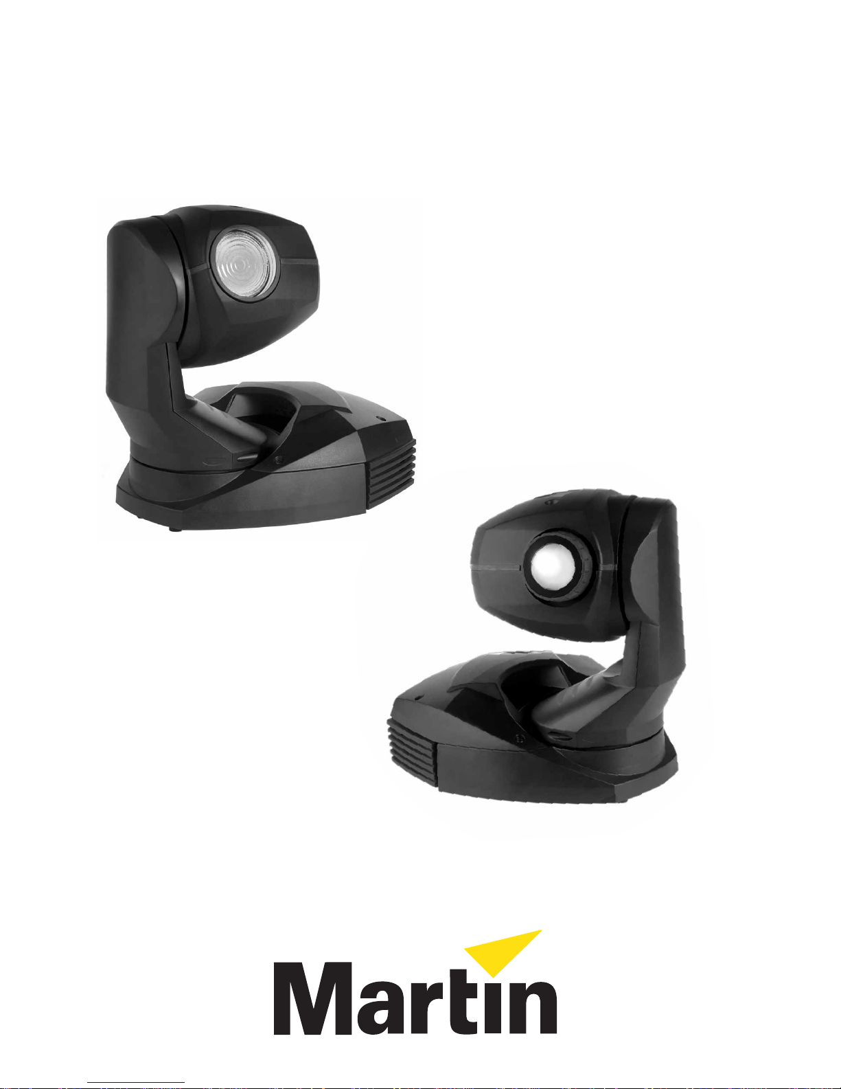
MiniMAC
user manual
MiniMAC Wash
MiniMAC Profile
Page 2
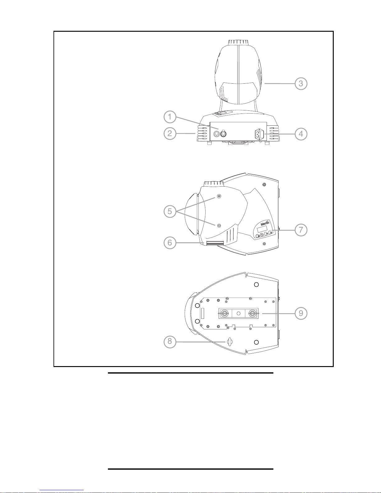
1 data connection
2 base fan
3 head fan
4 AC input & main fuse
5 cover locks
6 lamp access
7 control panel
8 eye bolt for safety cable
9 Omega clamp
attachment bracket
©1999 Martin Professional A/S, Denmark.
All rights reserved. No part of this manual may be
reproduced, in any form or by any means, without
permission in writing from Martin Professional A/S,
Denmark.
Printed in Denmark.
P/N 35000084, Rev. A
Page 3

NTRODUCTION
I
POWER
AC
NSTALLATION
I
ONTROL PANEL
C
ONTROLLER OPERATION
C
TAND-ALONE OPERATION
S
AMP
L
G
B
T
. . . . . . . . . . . . . . . . . . . . . . . . . . . . . . . . . . . . . . . . . . . . . 24
OBOS
ASIC SERVICE
ROUBLESHOOTING
. . . . . . . . . . . . . . . . . . . . . . . . . . . . . . . . . . . . . . . . . . . . 26
. . . . . . . . . . . . . . . . . . . . . . . . . . . . . . . . . . . . . . . 4
. . . . . . . . . . . . . . . . . . . . . . . . . . . . . . . . . . . . . . . . . . 6
. . . . . . . . . . . . . . . . . . . . . . . . . . . . . . . . . . . . . . . . 8
. . . . . . . . . . . . . . . . . . . . . . . . . . . . . . . . . . . . . 10
. . . . . . . . . . . . . . . . . . . . . . . . . . . . . . . . . . . . . . 28
. . . . . . . . . . . . . . . . . . . . . . . . . . . . . . . . . . . 32
. . . . . . . . . . . . . . . . . . . . . . . . . . . . . . 18
. . . . . . . . . . . . . . . . . . . . . . . . . . . . . . 21
DMX
S
PROTOCOL
PECIFICATIONS
. . . . . . . . . . . . . . . . . . . . . . . . . . . . . . . . . . . . . 33
. . . . . . . . . . . . . . . . . . . . . . . . . . . . . . . . . . . . . 36
3
Page 4

NTRODUCTION
I
Thank you for selecting the Martin MiniMAC Profile or MiniMAC Wash. Both of
these automated luminaires provide 12 dichroic color filters, high-speed mechanical
shutter, 540° of pan by 270° of tilt, 3-digit LED control panel, DMX, MC-1, standalone, and master/sl ave control options; and switch-selectable power supply
settings. The MiniMAC Profile provides a 17° hard-focused beam, manually
adjustable focus, and 7 interchangeable rotating gobos. The MiniMAC Wash
provides a soft-edged 23° beam.
1
SAFETY INFORMATION
Warning! This product is for professi on al us e only. It is not for hous ehol d
use.
This product presents risks of lethal o r severe injury due to fire and heat, electric
shock, ultraviolet radiation, lamp explosion, and falls.
powering or installing the fixture, follow the safety precautions listed below and
observe all warnings in this manual and on the fixture. If you have questions about
how to operate the fixture safely, plea se contact your Martin dealer or call the
Martin 24-hour service hotline at +45 70 200 201.
Read this manual
before
To protect yourself and others from electric shock
• Disconnect the fixture from AC power before removing or installing the lamp,
fuses, or any part, and when not in use.
• Always ground (earth) the fixtur e electrically.
• Use only a source of AC power that complies with local building and electrical
codes and has both overload and ground-fault protection.
• Do not expose the fixture to rain or moisture.
• Refer all service to a Martin service technician.
To protect yourself and others from UV radiation and lamp
explosion
• Never operate the fixture with missing or damaged lenses and/or covers.
4 Introduction
Page 5

• When replacing the lamp, allow the fixture to cool for at least 5 minutes before
opening the fixtur e or removing the lamp. Protect your hands and eyes with gloves
and safety glasses.
• Do not stare directly into the light. Never look at an exposed lamp while it is lit.
• Replace the lamp if it becomes defective or worn out.
To protect yourself and others from burns and fire
• Never attempt to bypass the thermostatic switch or fuses. Always replace defective
fuses with ones of the specified type and rating.
• Keep all comb ustib le materials (for e xample f abric, wood , paper) at least 0.3 mete rs
(12 inches) away from the fixture. Keep flammable materials well away from the
fixture.
• Do not illuminate surfaces within 0.3 meters (12 inches) of the fix ture.
• Provide a minimum clearance of 0.1 meters (4 inches) around fans and air vents.
• Never place filters or other materials over the lens.
• The exterior of the fixture can reach temperatures up to 60° C (140° F). All ow the
fixture to cool before handling.
• Do not modify the fixture or install other than genuine Martin par ts.
• Do not operate the fixture if the ambient temperature (Ta) exceeds 40° C (104° F).
To protect yourself and others from injury due to falls
• When suspending the fixture above ground level, verify that the structure can hold
at least 10 times the weight of all installed devices.
• Verify that all external covers and rigging hardware are securely fastened and use an
approved means of secondary attachment such as a safety cable.
• Block access below the work area whenever installing or removing the fixture.
UNPACKING
The packing material is carefully designed to protect the fixture during shipment always use it to transport the fixture.
The MiniMAC comes w ith:
• Martin Metal Halide 150 lamp
• 3 m, 3-pin IEC main s ca ble
• 5 m, black, 3-pin XLR data cable
• Attachment bracket for mounting clamp
• Eye bolt for safety cable
•user manual
Introduction 5
Page 6
AC
Wa rni ng! For protection from electric shock, the fixture must be grounded
Important! Install fuse and verify that power supply settings match local
POWER
The MiniMAC has switch-selectable settings to configure the power supply for
local conditions. The factory-default setting is indicated on the serial number label.
Always use the setting that is closest to the local AC supply.
(ear thed). The power supply s hall have overload an d groundfault protect ion.
AC supply before use .
2
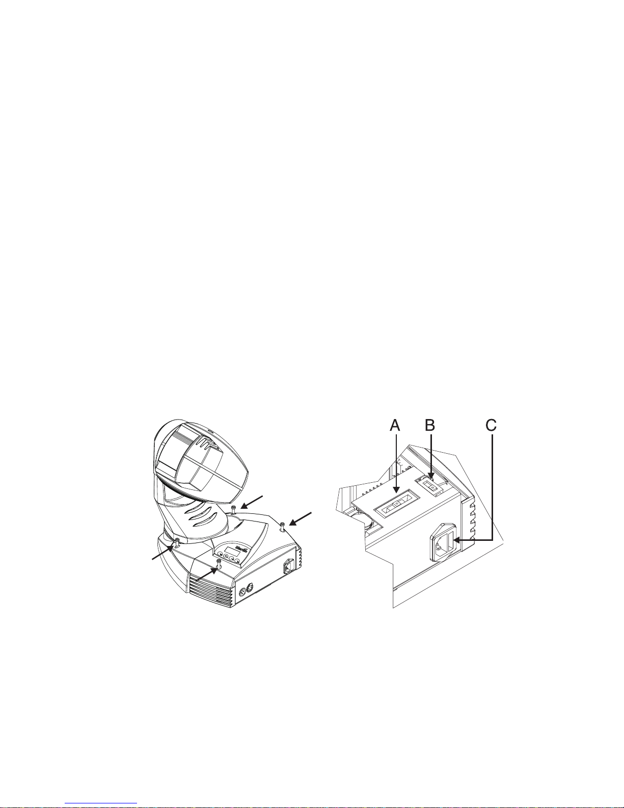
To change the voltage setting
1 Disconnect the fixture from power.
2 Remove the 4 base cover bolts with a 4 mm Allen wrenc h. Mo ve the co ver ou t of
the way of the switches without disconnecting wires.
3 Set the 5-position switch (A) to the setting closest to the AC voltage. Use the
higher setting if the voltage is halfway between 2 settings. For example, use the
230 V setting instead of the 210 V setting for operation with 220 V power.
4 Set the 2-position switch (B) to the AC frequency (50 / 60 Hz).
5 Replace the cover and apply a new power setting label to the serial number
label.
6 AC power
Page 7
To install the main fuse
Fuses are provided for 100 - 130 V and 200 - 250 V operation. Use only the fuse
specified for the operating voltage.
1 Locate the bag containing the fuse for your AC voltage. Insert the fuse in the
fuse holder. The holder may be packed with the other fuse.
2 Remove the label covering the mains input socket.
3 Insert the fuse holder in the empty slot in the mains input socket (C).
To install a plug on the power cable
The power cable must be fitted with a grounding-type cord cap that fits your power
distribution system. Consult an electrician if you have any doubts about proper
installation.
• Following the cord cap manufacturer’s instructions, connect the yellow and
green wire to groun d (earth), the brown wire to l ive, and the blue wire to neutral .
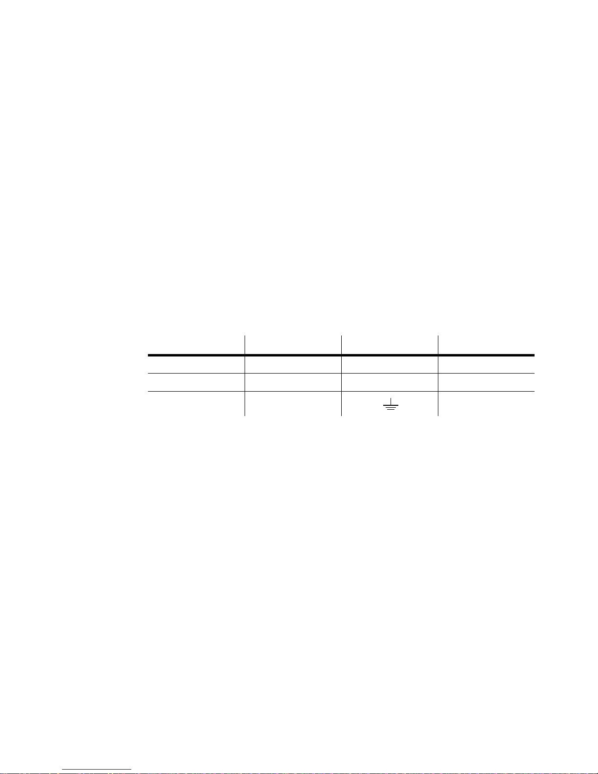
The table below shows some pin identification schemes.
Wire Pin Marking Screw color
brown live “L” yellow or brass
blue neutral “N” silver
yellow/green ground green
Table 1: Cord cap connections
To apply power
Warning! The power c ables must b e unda maged and ra ted for the
electrical requir ements of all conne cted d evices.
Impor tant! Powering th rough a dim mer syst em can damage t he fixt ure .
• Connect the prepared cable to the mains input socket and the AC mains
distribution system. Do not connect the fixture to a dimmer system.
AC power 7
Page 8

NSTALLATION
I
LOCATION AND ORIENTATION
For safe operation, install the Mini MAC in a location where
• it is at least 0.3 me te rs (12 inc h es) away from illuminated surf a c es and c ombustible
materials.
• it is not easily touche d or bumped.
• it is protected from rain and moisture.
• there is at least 0.1 meters (4 inches) clearance around the fans and air vents.
• there are no flammable materials nearby.
The MiniMAC may be installed in any o r ie nta tion by means of a r igging clamp (not
included) or placed directly on a stage or floor.
The intense light can burn or melt parts within a distan ce of 0.3 meters (12 inche s).
The MiniMAC is programmed to close its shutter if it illuminates its own base for
more than 10 seconds. When installing fixtures side-by-side, avoid illuminating one
fixture with another.
3
RIGGING
The MiniMAC includes a bracket for attaching a rigging clamp with 12 mm (1/2
in.) hardware. Clamps available from Martin are listed on page 37.
To rig the fixture
WARNING! Screw the included eye bolt securely into the base and fasten a
safety cable to th e eye bolt.
1 Verify that the clamp is undamaged and can bear at least 10 times the weight of
the fixture. Verify that the structure can bear at least 10 times the weight of all
installed fixtures, clamps, cables, auxiliary equipment, etc.
2 Bolt a clamp to the included bracket with a grade 8.8 (minimum) M12 bolt and
lock nut, or as recommended by the clamp manufacturer, through the 13 mm
hole in the bracket.
8 Installation
Page 9
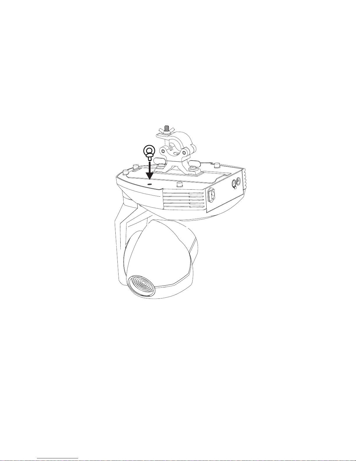
3 Align the bracket wi th the ke yholes in the b ase. Insert both loc king pi ns into the
holes and turn both levers a full 1/4 turn clockwise to lock.
The fasteners are
locked only when turned fully clockwise.
4 Screw the eye bolt securely into the base as shown below.
5 Block access below the work area.
6 Working from a stable platform, clamp the fixture to the structure.
7 Fasten a safety cable that can bear at least 10 times the weight of the fixture to
the structure and the eye bolt.
Installation 9
Page 10
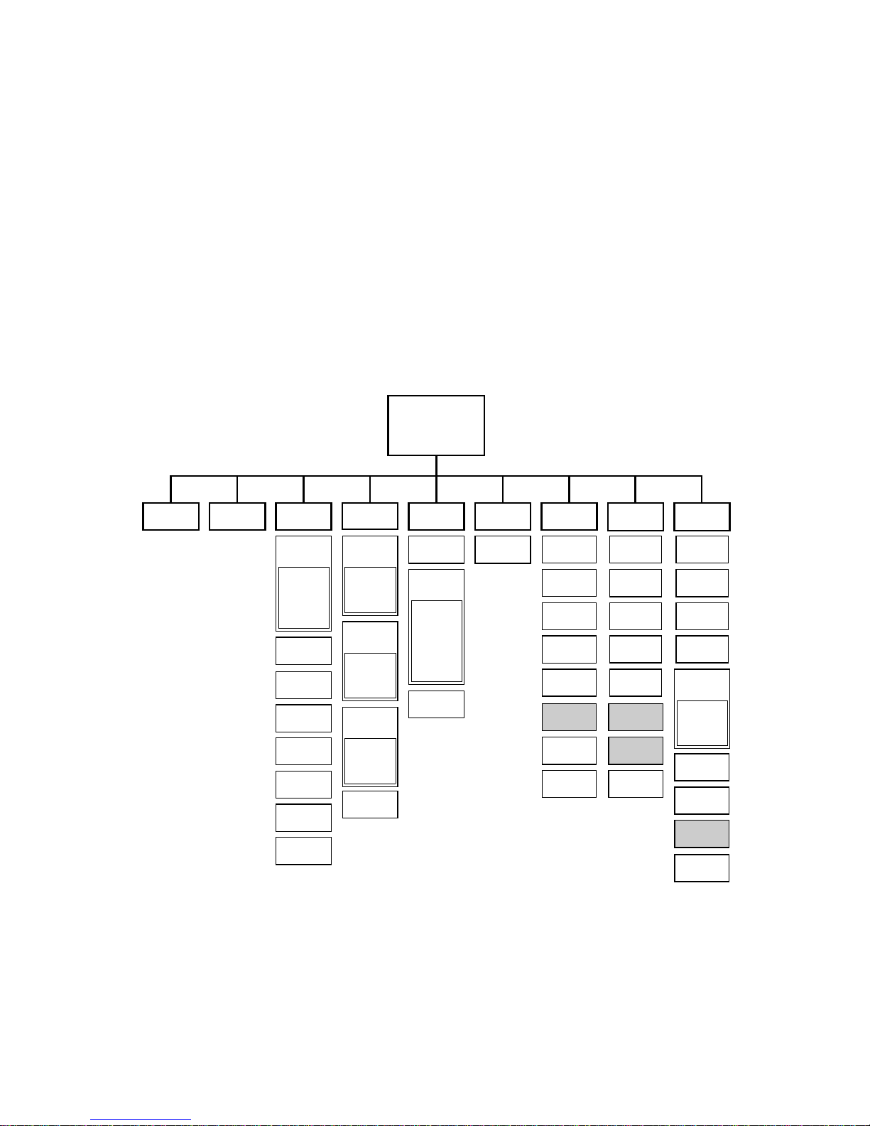
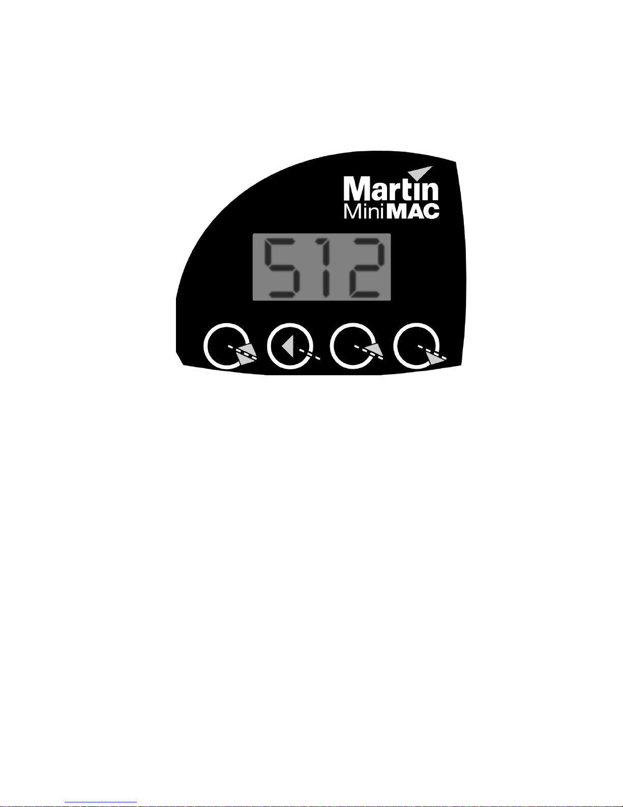
ONTROL PANEL
C
The control panel is used to set control modes, address, and personalities, display
information readouts, test, and manually control the fixture.
All user options ma y be set remotely v ia the ser ial link usi ng the Mar tin MP BB1
Uploader with version 1.4 or later software. Please refer to the MPBB1 manual for
details.
4
Address/
Info
Adr CtrtStPEr
Pro
P-t
P t
PIn
tIn
PtS
tyP
LOF
rES
ALO
dIS
FAC
Shaded items apply to MiniMAC Profile only.
InF
Hr
tot
rES
LHr
tot
rES
LSt
tot
rES
UEr
Control menu
tSE
LOg
StC
SHU
...
EFS
PCb
UTl
UPL
rst
LOn
LOF
SHU
COL
gob
PAn
tIL
AdJ
rst
LOn
LOF
SHU
COL
gob
rgo
P-t
SA
EnA
trg
rAt
Ctr
POS
PAn
tIL
SPd
COL
gob
FAC
10 Control panel
Page 11
To navigate the control menu
• The control address, or SA when in stand-alone mode, and any messages are
displayed at the top of the menu tree. From there, press [menu] to enter the
main menu. Press [up] or [down] to scroll through menus and press [enter] to
view submenus. To activate a setting or function, press [enter]. To return to the
previous menu or escape without making a selection, press [menu].
[menu] [enter] [up] [down]
To invert the display
• Press [up] and [down] at the same time .
Control panel 11
Page 12

Adj
adjustment menu
Pro
protocol, profile
Adr
ALO
Aut
COL
Ctr
dIS
EnA
FAC
FrE
FSt
gob
Hr
InF
Inu
address
automatic lamp on
auto-trigger
color
manual control, SA control
display
enable
factory settings
Fresnel (MiniMAC Wash)
fast
gobo selection
hours
information menu
inverse
P-t
PtS
rAt
rEC
rES
rgo
rnd
rst
SA
SHU
SLO
Snd
SPd
StC
pan/tilt menu
pan/tilt speed
rate
receive (SA slave)
DMX reset
gobo rotation
random
reset fixture
stand-alone menu
shutter
slow
sound, send (SA master)
speed
start code
LHr
LOF
LOg
LOn
LSt
nor
P t
PAE
PAF
PAn
PCb
PEr
PIn
POS
lamp hours
lamp off
DMX log
lamp on
lamp strikes
normal (medium)
pan/tilt swap
pan error time-out
pan fine
pan
printed circuit board
personalities
inverse pan
position
StE
SUr
tIE
tIF
tIL
tIn
tot
trg
tSE
tSt
tyP
UEr
UPL
Utl
settings error
sure?
tilt error time-out
tilt fine
tilt
inverse tilt
total
trigger
test sequence
test menu
fixture type
software version
upload
utilities menu
12 Control panel
Table 2: Menu abbreviations
Page 13

DMX MODE SETTING
The MiniMAC has 4 control modes for operation wi th DMX512 controllers. T he
modes mix tracking and vector control with 8 and 16-bit pan/tilt resolution in
different combinations to minimize channel requirements. Mode 1 provides basic
control and requires the fewest channels. Modes 2 and 3 provide some addit ional
control options. Mode 4 provides the full set of control options.
TRACKING VERSUS VECTOR CONTROL
With tracking control (al l mode s) the s peed at which an e ffect changes fro m one
position to another (fades) is determined by programming a fade time between 2
scenes using a cross-fader.
With vector control (modes 3 and 4), speed is programmed on separate speed
channels. This provides a way to program fades on controllers without cross-faders.
With some controllers, vector control provides smoother movement than tracking
control, particularly at slow speeds.
The speed channel must be set to “tracking speed” when using a cross-fader
(tracking control) to program fades.
The speed channel s al so provide a “b lackou t spe ed” that c aus es th e sh utter t o cl ose
while the effect is moving in order to make the transition invisible.
8-BIT VERSUS 16-BIT PAN/TILT RESOLUTION
8-bit pan/tilt resolution (modes 1 and 3) divides the pan and tilt ranges into 1 - 2°
increments. 16-bit resolution (modes 2 and 4) divides pan into 0.013° steps and tilt
into 0.007° steps for finer position control and smoother movement.
Mode Control Resolution MiniM AC Wash MiniMAC Profi le
1 Tracking 8-bit 4 channels 6 channels
2 Tracking 16-bit 6 channels 8 channels
3 Tracking/Vector 8-bit 6 channels 8 channels
4 Tracking/Vector 16-bit 8 channels 10 channels
To select DMX mode
Table 3: DMX mode summary
1 Scroll to
2 Press [enter] to activate the setting and return to the main menu.
Pro
in the main menu, press [enter], and scroll to the desired mode .
Control panel 13
Page 14

ADDRESS SELECTION
The control address, also known as the start channel, is the first channel used to
receive instructions from the controller. The total number of channels used depends
on the control mode.
Be sure to allow adequate channels when setting the control address. If control
channels for one fixture overlap control channels for another fixture, then one of the
fixtures will receive the wrong commands. To find the highest usable address
channel, subtract the number of channels required from the last controller channel
and add 1.
Two MiniMACs of the same type, and operating in the same control mode, may
share the same address if they are to respond identically. They will receive the same
commands and individual control will be impossible.
To set the control address
1 Scroll to
displayed.
2 Scroll to the address that is assigned to the fixture on the controller. Press
[enter] to activate the address setting.
Adr
in the main menu and press [enter]. The current address is
PERSONALITIES
The following settings are available to modify fixture behavior.
Pan/tilt swap:
more intuit ive control of fixtures mounted sideways.
Inverse pan:
Inverse tilt:
Pan/tilt speed:
Profile/Wash:
Map pan to the tilt channel and tilt to the pan channel to provide
Flip pan movement to right-to-left instead of left-to-right.
Flip tilt movement to down-to-up instead of up-to-down.
Optimize motor control for speed or smoothness.
For service use only - initializes softw are for fi xtu re type.
DMX lamp-off:
This helps prevent accidentally turning lamps off during a show.
DMX reset:
helps prevent accidentally resetting fixtures during a show.
Automatic lamp-on:
power to the fixture. Timing is staggered t o pr event excessive current draw.
Display:
14 Control panel
Disable the reset command unless channel 2 is set to color 12. This
Turn off the display 2 minutes after the last key press or leave it on.
Disable the lamp-off command unless channel 2 is set to color 12.
Strike lamps automatically within 90 seconds of applying
Page 15

To select a personality setting
1 Scroll t o
and press [enter].
2 Scroll to the desired option and press [enter].
PEr
in the main menu, press [enter], scroll to th e desired perso nalit y,
To restore default personality settings
1 Scroll to
[enter] twice to confirm and execute the command.
Personality Path Option Effect (Def ault setting bold)
Pan/tilt swap
Inverse pan
Inverse tilt
PEr
in the main menu, press [enter], and scroll to
P-t/P t
P-t/PIn
P-t/TIn
ON
OFF
ON
OFF
ON
OFF
Map pan to tilt channel and vice versa.
Select normal pan and tilt control.
Rev erse pan control (right Æ left).
Select normal pan (left
Rev erse ti lt control (down Æ up).
Select normal tilt (up
ÆÆÆÆ
right).
ÆÆÆÆ
down).
FAC
. Press
Pan/tilt speed
Profile/Wash
DMX lamp off
DMX reset
Automatic lamp
on
Display
PtS
tYP
LOF
rES
ALO
dIS
FSt
SLO
Pro
FrE
ON
OFF
ON
OFF
ON
OFF
ON
OFF
Table 4: Personalities
Optimize movement for speed.
Optimize movement for smoothness.
Initialize MiniMAC Profile.
Initialize MiniMAC Wash.
Enable lamp-off without confirmation.
Require confirmation of lamp-off.
Enable reset without confir mation.
Require confirmation of reset command
Strike lamp automatically within 90 seconds.
Strike lamp from controller.
Keep display lit.
Turn display off 2 minutes after key press.
Control panel 15
Page 16

READOUTS
The MiniMAC provides readouts to track usage, maintenance intervals, lamp life,
and software version. Values from 1000 to 9999 are automati cally scrolled and
counters reset to 0 when they reach 10,000.
Readout Path Option Displays
tot
Usage
Inf/Hr
rES
tot
Lamp usage
Inf/LHr
rES
tot
Lamp strikes
Software version
Inf/LSt
UEr
rES
- Version number of installed software.
Table 5: Readouts
To display or reset a readout
1 Scroll to
readout. Press [enter] and scroll to the desired option. Press [enter] to display
the information.
2 (Optional) To reset a counter, press [up] until the readout displays
Inf
in the main menu, press [enter] and scroll to the desired
Total hours with power on.
Hours with power on since counter was reset.
Recommended for tracking service intervals.
Total hours with lamp on.
Hours with lamp on since counter was reset.
Recommended for tracking lamp life.
Total number of lamp strikes.
Lamp strikes since counter was reset. Helps
evaluate lamp life.
0
.
TEST PROGRAMS
Test sequence:
Effects return to their home position at the end of the sequence before the test
repeats. To run the test, navigate to
the test, press [menu].
DMX log:
is useful for t rou bles hoo ting s et up e rro rs. F or e xamp le, if the f ix ture is prog ra mmed
for red but projects blue, che ck th e DMX log to find the value received for color. If
the value is for red (see the DMX protocol on page 33) then there is a problem with
the fixture. If the value is for blue, then the problem is with the programming, set
up, or link.
PCb:
damage to the circuit b oard.
16 Control panel
Displays the start code and the DMX value receiv ed for each effect. This
For service use only. Executing this test with motors connected may cause
This provides an easy way to test all e ffects without a controller.
tSt
tSE
/
run
/
and press [enter]. To stop
Page 17

To test DMX control values
1 Program a set of commands for the fixture.
2 Scroll to tSt in the main menu, press [enter] and scroll to
3 Press [enter] to display the start code. The start code must be 0. Press [menu].
4 Scroll through the effects and press [enter] to display the DMX values received.
Compare the values with the DMX protocol.
LOg
. Press [enter].
UPLOAD MODE
Software upload mode is normally engaged automatically. Use this option only if
automatic upload fails. See “Installing software” on page 29.
MANUAL AND ADJUSTMENT CONTROL
The manual contro l menu (
The adjustment menu (
• To reset the fixture, select
• To turn th e lamp on or off, select
• To open, cl ose, and strobe the shutte r at 3 speeds, select
• To move the color wheel to each position and scroll it at 3 speeds, select
• To move the gobo wheel to each position rotate gobos, select
• To control pan and tilt, select
Ctr
) permits limited operation from the control panel.
AdJ
) provides manual control for service use.
rST
.
LOn
PAn
and
or
tIL
LOF
.
.
SHU
.
Gob.
COL
.
STAND-ALONE CONTROL
The MiniMAC can be operated without a controller in stand-alone mode. Refer to
“Stand-alone operation” on page 21.
Control panel 17
Page 18

ONTROLLER OPERATION
C
This section describes operation with DMX controllers. The MiniMAC is also
compatible with the Ma rtin MC-1 Controll er with version 1.1 or later so ftware.
Please refer to the MC-1 user manual for details.
DATA CONNECTION
RECOMMENDED CABLE
Reliable data communication begins with the right cable. M ost microphone cable
does not transmit digital data reliably over long runs. For best results, use shielded,
twisted-pair cable designed for RS-485 applications with ORZýFDSDFLWDQFHýDQGýD
FKDUDFWHULVWLFэL PSHG DQFHэ RIэ еиэ WRэминэRKPVпэ7KH эPL QLPXP эZ LUHэ VL]Hэ L Vэн плэ PPэ хлй
$:*фэ IRUэ UXQ VэX Sэ WRэ кннэ PHWHU Vэ хмнннэ IWп фэD QGэ нпкл лэ PPэ хлзэ $:*фэIRUэUXQVэ XS
иннэPHWHUVэхмзйнэIWпфпэ
5
Your Martin dealer can supply the right cable in various lengths.
CONNECTIONS
The XLR data sockets are wired pin 1 to ground, pin 2 to signal - (cold), and pin 3
to signal + (hot). This is the standard pin assignment for DMX devices.
One or more adaptor cables may be required to connect the MiniMAC to the
controller and other lights if they have 5-pin connectors or reversed signal polarity
on pins 2 and 3.
5-pin to 3-pin
Adaptor
Male Female
1
2
3
4
5
1
2
3
3-pin to 5-pin
Adaptor
Male Female
1
2
3
1
2
3
4
5
3-pin to 3-pin
Phase-Reversing
Adaptor
Male Female
1
2
3
1
2
3
P/N 11820005
18 Controller operation
P/N 11820004
P/N 11820006
Page 19

To connect for controller operation
Male XLR
1
2
3
Male
P/N 91613017
120
Termination Plug
1 Connect a data cable to the controller’s data output. If controller has a 5-pin
output, use a 5-pin male to 3-pin female adaptor cable (P/N 11820005). Lead the
cable from the controller to the first fixture and plug it into the data input.
2 Connect the output of the fixture closest to the
controller to the input of the next fixture. If
connecting to a fixture with reversed-polarity (pin 3
cold), insert a phase-reversing cable between the tw o
fixtures.
3 Continue connecting fixtures output to input. Up to
32 devices may be connected on a serial link.
4 Terminate the link by inserting a male termination
plug (P/N 91613017) into the data output of the last
fixture. A termination plug is simp ly an XLR
connector with a 120 ohm, 0.25 W resistor soldered
across pins 2 and 3.
CONTROLLABLE EFFECTS
LAMP POWER
Lamp power can be switched on and off from the controll er. When set up for
contr ol ler operation, and with the automatic la mp-on p ersona lity set to of f, the la mp
remains off until a lamp-on command is sent.
Note: A peak of electric current many times the operating current is drawn briefly
when striking a lamp. Striking many discharge lamps at once may cause a voltage
drop that prevents lamps from striking or trips circuit breakers. When striking
multiple fixtures, space lamp-on commands at 5 second intervals.
The lamp must be allowed to cool for several minutes after turning it off before it
can be turned back on. To prevent accidental lamp-off commands, this command
can be partially disabled from th e control panel: see page 14. If a hot la mp does not
strike, send the lamp off command and wait several minutes before trying again.
RESET
All effects can be reset to their index positions from the controller. To prevent
accidental resets, the command can be partially disabled from the control panel: see
page 14.
Controller operation 19
Page 20

SHUTTER
The mechanical shutter opens, closes, and strobes at variable and random rates up to
11.4 Hz. The shutter closes automatically after 10 seconds if the light beam is
projected on the base to prevent heat damage. The shutter opens instantly when the
beam is moved.
STAND-ALONE MODE
“Stand-alone” operation may be activated from the controller.
COLOR
The color wheel provides continuous-scroll for split-color effects and stepped-scroll
for full-color positions. The wheel rotates continuously at variable speed and
provides a random color function.
GOBOS
The MiniMAC Profile provides 7 interchangeable gobos that shake, swing, and
rotate at variable speed. The wheel also provides a random gobo function.
PAN AND TILT
The head pans 540° and tilts 270°. If knocked or jarred out of position, pan and tilt
are reset automatically when the head reaches one of its limits.
20 Controller operation
Page 21

TAND-ALONE OPERATION
S
The MiniMAC can be operated without a controller in stand-alone mode in which
action is triggered by sound, using a built-in microphone, or automatically, using an
internal timer.
Operation can be modified with the options listed on page 23.
To operate a single fixture
6
1 Scroll to SA in the main menu, press [enter], scroll to
Sin
scroll to
2 Scroll to
3 Modify behavior with the options in Table 6.
4 Disconnect the fixture from power to stop operation.
5 To disable stand-alone operation, set
, and press [enter].
EnA
, press [enter], scroll to On or
EnA
to
Aut
, and press [enter].
OFF
.
Ctr
, press [enter],
To operate multiple fixtures in stand-alone mode
Sev e r a l MiniMACs may be c onnected together for s y nc hronous operation without a
controller. They are connected together and one, the master, sends control
instructions to the others. Up to 32 fixtures - both Profile and Wash versions - can be
can be connected an d operated this way.
Impor tant! Set only 1 fixture as master : errors and damage can oc cur if
there is more th an 1 d evice send ing co ntrol sign als.
1 Select any one fixture to be the master. On this fixture only, scroll to SA in the
main menu, press [enter], scroll to
press [enter].
Ctr
, press [en ter], scroll to
Snd
, and
2 On all slave fixtures, scroll to
Ctr
, press [enter], scroll to
SA
in the main menu, press [enter], scroll to
rEC
, and press [enter].
Stand-al on e operation 21
Page 22

3 Plug a data cable into the OUT socket of the first
Female XLR
1
2
3
Female
120
Termination Pl ug
P/N 91613018
fixture and the IN socket of the next fixture. Repeat as
required to connect up to 32 MiniMACs (Profiles and
Washes).
4 Insert a female termination plug (P/N 91613018) into
the IN socket of the first fixture. Insert a male
termination plug (P/N 91613017) into the OUT socket
of the last fixture. A termination plug i s an XLR
connector with a 120 ohm, 0.25 W resistor soldered
across pins 2 and 3.
EnA
5 On all fixtures, scroll to
On
6 Set the trigger and pan/tilt options using the control panel on the master
fixture. Set the color and gobo options on the slave fixtures. See Table 6. Note:
The inverse pan and inverse tilt personalities may also be us ed to mod ify
behavior. See Table 4.
7 Disconnect the fixture from power to stop operation.
or
Aut
, and press [enter].
, press [enter], scroll to
8 To disable stand-alone operation, set
EnA
to
OFF
.
22 Stand-alone oper a tion
Page 23

Setting SA mode Path Option Effect (Default setting bold)
SA enable all
SA trigger
SA trigger rate
SA control mode
Low pan position
High pan position
Low tilt position
single,
master
single,
master
single
master
slave
single,
master
EnA
trg
rAt
Ctr
POS/PAN
/Lo
POS/PAN
/HI
POS/tIL
/Lo
ON
OFF
Aut
Snd
Aut
0
.5 -
Sin
Snd
rEC
255
0
..
0
255
..
255
0
..
Enable stand-alone operation
Disable stand-alone operation
Enable stand-alone operation
automatically if there is no DMX signal
for 5 seconds.
Sound trig ger
Timed trigger
10
Set timed trigger pulse from 0.5 to 10
seconds
Set up a single fixture
Set up a master fixture
Set up a slave fixture
Set one end of pan range
Set other end of pan range
Set one end of tilt range
High tilt position
Pan/tilt speed
Slave color slave
Slave gobo sla ve
Defaults all
single,
master
POS/tIL
..
Set other end of tilt range
0
255
/HI
FSt
SPd
nor
SLO
nor
COL
Inu
rnd
nor
Gob
Inu
rnd
FAC
Table 6: Stand-alone parameters
-
Select fast movement
Select medium speed movement
Select slow movement
Slave color same as master
Slave color opposite master
Random slave color
Slave gobo same as master
Slave gobo opposite master
Random slave go bo
Restore factory default stand-alone
settings
Page 24

AMP
L
COMPATIBLE LAMPS
The MiniMAC is designed to use either the Martin Metal Halide 150, included, or
the Osram HTI 150 discharge lamp.
Impor tant! Installing a ny other lamp may d amage th e fixt ure.
Lamp Efficiency Color Temp. Average Life
MMH 150 67 lm/W 5000K 2000 hr.
HTI 150 67 lm/W 6500K 750 hr.
Table 7: Lamp specifications
7
To replace the lamp
WARNING! Wear safety glasses and allow the lamp to cool for at least 5
minutes before opening th e head.
1 Disconnect the fixture from power and allow it to cool.
2 Pry/pull open the lamp access cover from the ribbed end.
3 Remove the 3 outside screws (A) with a Pozidriv #1 screwdriver and remove the
lamp socket assembly.
4 Remove the old lamp from the socket.
24 Lamp
Page 25

5 Holding the new lamp by its ceramic base (do not touch the glass), align the
small pin with the small hole and insert the lamp squarely into the soc ket. Make
sure that the 4 small projections on the base contact the socket.
6 If your fingers touched the glass bulb, clean it with a clean, lint-free cloth
wetted with alcohol.
7 Insert the lamp assembly and replace the screws (A).
8 Reset the lamp hour and lam p strike counters as described on page 16.
To align the lamp
The lamp is pre-aligned at the factory. Realignment when changing the lamp may
improve performance.
1 Strike the lamp and shine the light on a flat surface.
2 Center the hot-spot (the brightest part of the beam) with small turns of the
adjustment screws (B) using a Pozidriv #2 screwdriver. If there is no hot-spot,
adjust the reflector until the light is even.
3 To reduce a hot-spot, turn all 3 screws clockwise (B) 1/4-turn at a time until the
light is evenly di s tr ibute d.
4 If the light is bright er ar ound t he edge than it is in th e center, or if light output is
low, the lamp is too far back in the reflector. Turn the adjustment screws (B)
counterclockwise 1/4-turn at a time until the light is bright and evenly
distributed.
5 If you have trouble aligning the lamp, remove the lamp and check that it is
seated squarely in the socket.
Lamp 25
Page 26

OBOS
G
The MiniMAC Profile uses gobos as specified on page 37. The correct orientation
for differen t g obo t yp es is shown below. When in dou bt , insta ll g obos with the m o re
reflective side towards the lamp.
To change gobos
1 Turn off the lamp and allow it to cool for at least 5 minutes. Disconnect the
fixture from power.
2 Unlock the head cover fasteners by turning them a quarter-turn
counterclockwise. Pry open the lamp access cover from the ribbed end and
remove the head cover.
3 Tilt the head up.
access the gobo. Squeeze the ends of the gobo spring
together and re move it. Tilt the head down and catch
the gobo as it falls out.
Turn the gobo wheel as required to
8
4 Tilt the head back up and drop the replacement gobo
in the holder. Squeeze the spring together and
carefully place it over the gobo.
To focus gobos
• Project a gobo on a surface 2 meters or more away from the fixture. Turn the
front lens as required to focus the pattern.
26 Gobos
Page 27

Uncoated side towards stageCoated side towards lamp
When an object is held up to the
coated side there is no space between
the object and its reflection. The back
Coated glass gobos
edge of the gobo cannot be seen
when looking through the coated side.
Smooth side towards lamp
When an object is held up to the
uncoated side there is a space between
the object and its reflection. The back
edge of the gobo can be seen when
looking through the uncoated side.
Textured side towards stag e
Textured glass gobos
Reflective side towards lamp Black side towards stage
Metal gobos
True image towards lamp Reversed image towar ds sta ge
Image/text gobos
Gobo orientation
Gobos 27
Page 28

ASIC SERVICE
B
The MiniMAC requires simple routine maintenance. The schedule depends heavily
on the operating environment; please consult a Martin service technician for
recommendation s.
Refer all service not described here to a qualified Martin technician .
Impor tant! Excessive d ust, g rease, and s moke f luid buildu p degrad es
performance an d cause s overheat ing and damage t o the fixtur e
that is not covered by the warranty.
Warning! Disconnect t he fixt ure from p ower before r emoving any cover.
9
To open the head
1 Turn off the lamp and allow it to cool for at least 5 minutes. Disconnect the
fixture from power.
2 Unlock the head cover fasteners by turning them a quarter-turn
counterclockwise.
3 Open the lamp access cover by pulling from the ribbed end.
4 Pull off the top head cover.
5 When replacing the cover, turn the fasteners a half to a quarter turn clockwise
until they click.
Do not overtighten
CLEANING
To clean optical components
Use care when cleaning optical components. The surface of the color filters is
fragile and small scratches may be visible.
1 Disconnect the fixture from power and allow the components to cool
completely. Remove the head cover.
.
2 Blow or vacuum away loose dust. Remove residues fr om lenses and filters with
a soft cloth or cotton swabs wetted with isopropyl alcohol. Regular glass
cleaner may also be used, but no residues may remain.
28 Basic servic e
Page 29

3 Rinse with distilled water. Mixing the water with a small amount of wetting
agent such as Kodak Photoflo will help prevent streaking and spotting.
4 Dry with a clean, soft and lint-free cloth or blow dry with compressed air.
To clean the fan and air vents
To maintain ade quate cooling, dust must be cleaned from th e fan and air vents
periodically.
• Remove dust and dirt from the fans and vent grills using a soft brush, cotton
swab, vacuum, or compressed air.
INSTALLING SOFTWARE
Updates of the MiniMA C control software are released when features are added and
improved . The latest v ersion is a vailable for downlo ad from the Se rvice and Suppo rt
area of the Martin Professional web site at http://www.martin.dk. Software is
installed using a Martin uploader such as the MPBB1 wit h version 1.4 or later
software.
To install software, normal method
Important! The data link must be terminated as described on page 19.
1 Download the latest control software from the Martin Professional web site at
http://www.mart in.dk. Install the software in a Martin MPBB1 uploader.
2 Connect the uploader to the fixture as you would a controller. Apply power to
the uploader and the fixtures.
3 After the fixture has finished resetting, select
dMX
and press [enter]. Select
installed when the MPBB1 displays
disconnect the MPBB1.
4 If a check-sum error (
interrupted or corrupted during transmission. Reattempt the upload using
backup method I.
CSE
and press [enter]. Wait. The software has been
dONE
) occurs and/or the fixture does not reset, data was
UPLd
and the fixtures reset. Turn off and
from the uploader menu
To install software, backup method I
Follow this procedure exactly as described to install software if a normal upload
attempt is unsuccessful and a check-sum error (
CSE
) occurs.
1 Disconnect the fixture from power: it must be off at least 10 seconds.
apply power to the fixture until the uploader is connected and ready.
Do not
Basic servic e 29
Page 30

2 Connect the uploader to the fixture as you would a controller.
link
.
Terminate the
3Select
press [enter] yet.
4 Apply power to the fixture. The control panel displays
b
5 Wait. The software has been installed when the MPBB1 displays
the fixture resets. Disconnect the uploader.
UPLd
. When b is displayed,
from the uploader menu and press [enter]. Select
wait 5 seconds
and then press [enter] on the MPBB1.
To install software, backup method II
Use this procedure to install software only if all else fails.
1 Disconnect the fixture from the data link and power.
2 Use tweezers to move the jumper on
PL107 on the main circuit board to the
boot setting as shown.
3Select
and press [enter]. Se lect
press [enter] yet.
4 Connect the uploader to the fixture as
you would a controller.
UPLd
from the uploader menu
boot
Terminate the link
Do not
.
.
PL107
CSE
boot
, then
boot settingnormal setting
Do not
.
bSL
dONE
PL107
, then
and
5 Apply power to the fixture and wait 5 seconds.
6 Press [enter] on the MPBB1. Wait. The software has been installed when the
MPBB1 displays
7 Disconnect the fixture from power and move the jumper back to the normal
setting.
dONE
and the fixture resets.
30 Basic servic e
Page 31

REPLACING FUSES
The MiniMAC has 3 fuses. The main fuse is in the mains input socket. The
secondary fuses are on the pri nt ed circuit board.
Warning! Never replace fuses wit h one s of a differe nt rati ng!
To replace the main fuse
1 Unplug the mains cable from the input socket. Pry open the fuse holder and
remove the fuse.
2 Replace the fuse with one of the same type. The fuse rating is listed on serial
number label and in the specifications.
To replace secondary fuses
1 Disconnect the fixture from power.
2 Remove the 4 base cover bolts with a 4 mm Allen wrench. Move the cover
without disconnecting wires.
3 Pry out the defective fuse and replace it with one of the same rating.
4 Replace the cover before applying power.
Basic servic e 31
Page 32

ROUBLESHOOTING
T
Problem Probable cause(s) Remedy
No power to fixture. Check power cables.
10
No response from fixture.
Fixture resets but does not
respond correctly to controller.
Fixture does not reset. An effect requires adjustment. Contact service technician.
No light.
Primary fuse blown. Replace fuse.
Secondary fuse blown. Replace fuse.
Controller not connected. Connect controller.
Incorrect addressing of the
fixtures.
Controller pin-out does not
match fixture pin-out (signal
reversed).
Bad data link connection Inspect cables and correct
Data link not terminated. Insert termination plug in
Defective fixture or 2 devices
transmitting on link.
Lamp missing or blo wn Disconnect fixture and replace
Check address and mode
settings on fixture and
controller.
Insert a swapper cable in data
input.
poor connections and/or
broken cables.
output of last fixture.
Bypass fixtures one at a time
until normal operation is
regained: unplug both
connectors and connect them
directly together.
lamp.
Lamp cuts out intermittently or
burns out too quickly.
StE
(memory error)
message displayed
PAE
(pan error time-out)
message displayed
TIE
(tilt error time-out)
message displayed
CSE (check-sum error)
message displayed
32 Troubleshooting
Fixture is too hot. Allow fixture to cool.
Incorrect power supply setting. Check setting.
The user settings cannot be
read from memory.
Pan reset switch malfunction. Contact service technician.
Tilt reset switch malfunction. Contact service technician.
Unsuccessful software upload. See “Installing software”.
Contact service technician.
Page 33

DMX
MiniMAC Wash MiniMAC Profile
12341234 Value Percent Function
* If command is disabled in
menu, it can be executed only if
the color wheel is set to color 12.
PROTOCOL
1
1
0 - 19
20 - 49
50 - 112
113 - 127
128 - 137
138 - 147
148 - 157
158 - 167
168 - 177
178 - 187
188 - 207
208 - 217
218 - 227
228 - 237
238 - 247
248 - 255
0 - 7
7 - 19
19 - 44
44 - 50
50 - 53
54 - 57
58 - 61
62 - 65
66 - 69
70 - 73
74 - 81
81 - 85
85 - 87
89 - 93
93 - 97
97 - 100
Shutter, Strobe, Reset, Lamp On/Off
Shutter closed
Shutter open
Strobe, fast to slow
Shutter open
Random strobe, fast
Random strobe, medium
Random strobe, slow
Shutter open
Stand-alone w/ music trigger
Stand-alone w/ auto trigger
Shutter open
*Reset
Shutter open
Lamp on
Shutter open
*Lamp off: hold for 5 seconds
A
0 - 150
0
12
24
36
48
22
60
72
84
96
108
120
132
144
0 - 59
0
4
9
14
18
23
28
33
37
42
47
52
56
Color
Continuous scroll
White
Color 1
Color 2
Color 3
Color 4
Color 5
Color 6
Color 7
Color 8
Color 9
Color 10
Color 11
Color 12
DMX protocol 33
Page 34

MiniMAC Wash MiniMAC Profile
12341234 V alue Percent Function
Color
Stepped scroll
151 - 159
160 - 163
164 - 167
168 - 171
172 - 175
176 - 179
180 - 183
184 - 187
188 - 191
22
192 - 195
196 - 199
200 - 203
204 - 207
59 - 62
63 - 64
64 - 65
66 - 67
67 - 68
69 - 70
70 - 72
72 - 73
74 - 75
75 - 76
77 - 78
78 - 79
80 - 81
Color 12
Color 11
Color 10
Color 9
Color 8
Color 7
Color 6
Color 5
Color 4
Color 3
Color 2
Color 1
White
Continuous rotation
208 - 245
81 - 96
CW, fast to slow
246 - 248
249 - 251
252 - 255
0 - 20
21 - 35
36 - 50
51 - 65
66 - 80
81 - 95
96 - 110
111 - 125
-3
126 - 145
146 - 165
166 - 185
186 - 205
206 - 225
226 - 245
96 - 97
98
99 - 100
0 - 7
8 - 13
14 - 19
20 - 25
26 - 31
31 - 37
37 - 43
43 - 49
49 - 57
57 - 65
65 - 72
73 - 80
81 - 88
89 - 96
Random color
Fast
Medium
Slow
Gobo Selection and Shake
Gobo selection
Open
Gobo 1
Gobo 2
Gobo 3
Gobo 4
Gobo 5
Gobo 6
Gobo 7
Gobo shake
Gobo 6, slow to fast
Gobo 5, slow to fast
Gobo 4, slow to fast
Gobo 3, slow to fast
Gobo 2, slow to fast
Gobo 1, slow to fast
34 DMX protocol
246 - 248
249 - 251
252 - 255
96 - 97
98
99 - 100
Random gobo
Fast
Medium
Slow
Page 35

MiniMAC Wash MiniMAC Profile
12341234 Value Percent Function
Gobo Rotation and Swing
(select gobo on ch. 3)
0 - 2
-4
3 - 117
118 - 232
233 - 239
0
1 - 46
46 - 91
91 - 94
No rotation
CW rotation, slow to fast
CCW rotation, fast to slow
No rotation
240 - 255
35
-4-4-6-6
45456767
-6-6-8-8
--57--79
--68--810
0 - 255 0-100
0 - 255 0-100
0 - 255 0-100
0 - 255 0-100
0 - 2
3 - 245
246 - 248
249 - 251
252 - 255
0 - 2
3 - 251
252 - 255
94 - 100
0
1 - 96
96 - 97
98
99 - 100
0
1 - 96
97 - 100
Gobo swing, slow to fast
Pan
Left to right (128 = neutral)
Pan fi ne (LSB)
Left to right
Tilt
Up to down (128 = neutral)
Tilt fine (LSB)
Up to down
Pan/Tilt Speed
Tracking mode
Fast to slow
Tracking,
Tracking,
Blackout while moving
Effects Speed
Tracking mode
Fast to slow
Blackout while moving
PtS=SLO
PtS=FSt
DMX protocol 35
Page 36

PECIFICATIONS
S
PHYSICAL
Length: . . . . . . . . . . . . . . . . . . . . . . . . . . . . . . . . . . . . . . . . . . . . . . . . . . . . 390 mm (15.4 in)
Width: . . . . . . . . . . . . . . . . . . . . . . . . . . . . . . . . . . . . . . . . . . . . . . . . . . . . 316 mm (12.4 in)
Height: . . . . . . . . . . . . . . . . . . . . . . . . . . . . . . . . . . . . . . . . . . . . . . . . . . . . 415 mm (16.3 in)
Weight, MiniMAC Profile: . . . . . . . . . . . . . . . . . . . . . . . . . . . . . . . . . . . . 11.8 kg (26.0 lbs)
Weight, MiniMAC Wash: . . . . . . . . . . . . . . . . . . . . . . . . . . . . . . . . . . . . . 11.6 kg (25.5 lbs)
B
SOURCE
Martin Metal Halide 150 (included): . . . . . . . . . . . . . . . .150 W, 67 Lm/W, 2000 hr., 5000K
Osram HTI 150 (opti on al ): . . . . . . . . . . . . . . . . . . . . . . . .150 W, 67 Lm/W, 750 hr., 6500K
OPTICS, MINIMAC PROFILE
Focused beam angle: . . . . . . . . . . . . . . . . . . . . . . . . . . . . . . . . . . . . . . . . . . . . . . . . . . . . .17°
Focus: . . . . . . . . . . . . . . . . . . . . . . . . . . . . . . . . . . . . . . . . . . . . . . . . 2 m (6.5 ft.) to infinity
Outside gobo dia meter: . . . . . . . . . . . . . . . . 22. 5 mm + 0/- 0.3 mm (0.886 in +0/- 0.01 2 in)
Maximum gobo image diameter: . . . . . . . . . . . . . . . . . . . . . . . . . . . . . . 17.0 mm (0.669 in)
Maximum gobo thickness: . . . . . . . . . . . . . . . . . . . . . . . . . . . . . . . . . . . .1.1 mm (0.043 in)
OPTICS, MINIMAC WASH
Field angle: . . . . . . . . . . . . . . . . . . . . . . . . . . . . . . . . . . . . . . . . . . . . . . . . . . . . . . . . . . . .23°
Focus: . . . . . . . . . . . . . . . . . . . . . . . . . . . . . . . . . . . . . . . . . . . . . . . . . . . . . . . . . . . . . . fixed
DATA COMMUNICATION
Hardware standard: . . . . . . . . . . . . . . . . . . . . . . . . . . . . . . . . . . . . . . . . . . . . . . . . . . RS-485
Data I/O: . . . . . . . . . . . . . . . . locking 3-pin XLR, pi n 1 shield, pin 2 cold (-), pin 3 hot (+)
Recommende d cable: . . 24 AWG (min.), low capacitance, 85- 150 Ω shielded twisted pair
36 Specifications
Page 37

INSTALLATION
Mounting points: . . . . . . . . . . . . . . . . . . . . . . . . . . . . . . . . . . . . . . . 1 pair of 1/4-turn locks
Orientation: . . . . . . . . . . . . . . . . . . . . . . . . . . . . . . . . . . . . . . . . . . . . . . . . . . . . . . . . . . . . any
Minimum distance to combustible materials: . . . . . . . . . . . . . . . . . . . . . . . . . . 0.3 m (12 in)
Minimum distance to illuminated surfaces: . . . . . . . . . . . . . . . . . . . . . . . . . . . 0. 3 m (12 in)
Minimum clearance around fan and air vents: . . . . . . . . . . . . . . . . . . . . . . . . . . 0.1 m (4 in)
THERMAL
Maximum ambient temperature (Ta): . . . . . . . . . . . . . . . . . . . . . . . . . . . . . . .40° C (104° F)
Maximum surface temperature: . . . . . . . . . . . . . . . . . . . . . . . . . . . . . . . . . . .60° C (140° F)
AC SUPPLY
AC input: . . . . . . . . . . . . . . . . . . . . . . . . . . . . . . . . . . . . . . . . . . . . . . 3-pin IEC male socket
Power supply options: . . . . . . . . . . .100/120/210/230/250 V, 50/60 Hz (switch-selectable)
MAXIMUM POWER AND CURRENT
100 V, 50 or 60 Hz: . . . . . . . . . . . . . . . . . . . . . . . . . . . . . . . . . . . . . . . . . . . . . . 220 W, 2.7 A
120 V, 50 or 60 Hz: . . . . . . . . . . . . . . . . . . . . . . . . . . . . . . . . . . . . . . . . . . . . . . 210 W, 2.0 A
210 V, 50 or 60 Hz: . . . . . . . . . . . . . . . . . . . . . . . . . . . . . . . . . . . . . . . . . . . . . . 200 W, 1.3 A
230 V, 50 or 60 Hz: . . . . . . . . . . . . . . . . . . . . . . . . . . . . . . . . . . . . . . . . . . . . . . 200 W, 1.1 A
250 V, 50 or 60 Hz: . . . . . . . . . . . . . . . . . . . . . . . . . . . . . . . . . . . . . . . . . . . . . . 210 W, 1.0 A
FUSES
2
Primary fuse, 200 - 250 V: . . . . . . . . . . . . . . . . . . . . . . . . . . . . . . .T 3.15 A, high I
Primary fuse, 100 - 130 V: . . . . . . . . . . . . . . . . . . . . . . . . . . . . . . .T 3.15 A, high I
Fuse F401: . . . . . . . . . . . . . . . . . . . . . . . . . . . . . . . . . . . . . . . . . . .T 3.15 A, high I
t, 250 V
2
t, 250 V
2
t, 250 V
Fuse F402: . . . . . . . . . . . . . . . . . . . . . . . . . . . . . . . . . . . . . . . . . . . . . . . . . . .T 2.5 A, 250 V
CONSTRUCTION
Housing: . . . . . . . . . . . . . . . . . . . . . . . . . . . . . . . . . UV-resistant fiber-reinforced composite
Finish: . . . . . . . . . . . . . . . . . . . . . . . . . . . . . . . . . . . . . . . . . . . . . . . . . . .black, integral color
Protection factor: . . . . . . . . . . . . . . . . . . . . . . . . . . . . . . . . . . . . . . . . . . . . . . . . . . . . . IP 20
ACCESSORIES
G-clamp: . . . . . . . . . . . . . . . . . . . . . . . . . . . . . . . . . . . . . . . . . . . . . . . . . . . . . . . . .91602003
Half-coupler clamp: . . . . . . . . . . . . . . . . . . . . . . . . . . . . . . . . . . . . . . . . . . . . . . . .91602005
Optional gobos: . . . . . . . . . . . . . . . . . . . . . . . . . . . . . . . . . . . MAC 250 size, see catalogue
Specifications 37
 Loading...