

Page 1
OWNER’S INSTALLATION, SAFETY
AND OPERATIONS MANUAL
GRAVITY VENTED WALL FURNACE SERIES: MDV8P, MDV8N, MDV12P, MDV12VP,
MDV12N, MDV12VN, MDV20P, MDV20VP, MDV20N, MDV20VN
Your heater may differ from models shown.
Conforms to ANSI STD Z21.86-2008
and certified to CSA STD 2.32-2008 (R2014), and CGA 2.17-M91 (R2009)
0544GH001S
This Appliance may be installed in an aftermarket,
permanently located, manufactured home (USA
only) or mobile home, where not prohibited by
local codes.
This appliance is only for use with
the type of gas indicated on the
rating plate. This appliance is not
convertible for use with other gases.
INSTALLER: Leave this manual with
the appliance.
CONSUMER: Retain this manual for
future reference.
WARNING: If the information in these instructions
are not followed exactly, a fire or explosion may
result causing property damage, personal injury,
loss of life.
Do not store or use gasoline or other flammable
vapors and liquids in the vicinity of this or any
other appliance.
WHAT TO DO IF YOU SMELL GAS:
* Do not try to light any appliance.
* Do not touch any electrical switch; do not
use any phone in your building.
* Immediately call your gas supplier from a
neighbor's phone. Follow the gas supplier's
instructions.
* If you cannot reach your gas supplier, call
the fire department.
Installation and service must be performed by
a qualified installer, service agency or the gas
supplier.
We thank you for purchasing our quality and reliable MARTIN heater. If you require assistance or have
any questions about safety, installation, operation, require replacement parts, safety label or manual, please
contact our customer service:
Call us toll-free at 1-800-266-1414 Monday to Friday 8H AM to 17 H PM
Or email us at sales@bismar.com www.bismar.com
Bismar Inc., 9, de Montgolfier st., Boucherville, Qc, J4B 8C4
®
V1-6.2016
Page 2
INTRODUCTION
Your MARTIN® heater is especially designed to provide maximum comfort to you and your home. Its large solid injected
aluminum front grill assures the optimum use of the generated heat in the ambient, maintains normal temperatures behind
the heater to avoid sticking of particles, which would soil the wall. You can feel safe with absolute security guaranteed by:
A flame failure safety, which cuts the gas supply in the event of the heater pilot extinguishing due to strong air currents
•
or momentary interruption of the supply of gas.
Its gas pressure regulator assures an optimum operational function, avoiding peak pressures in the gas supply
•
affecting normal combustion.
Its tight gas combustion chamber, totally enameled avoids gases which are caused by combustion to contaminate
•
the air and ensures a useful, long lasting working life.
A guarantee of long lasting comfort provided by this heater and its quality components, the high technology applied
in the process of fabrication and especially by the traditional vocation of MARTIN® to supply durable products for your
maximum comfo
rt and satisfaction.
LOCAL CODES
Install and use the heater with care. The installation must conform with local codes or in the absence
of local codes, use the latest edition of The National Fuel Gas Code ANSI Z223.1/NFPA 54 Natural
Gas and Propane Installation Code, CSA B149.1.
A manufactured home (USA only) or mobile home OEM installation must conform with the
tured Home Construction and Safety Standard, Title 24 CFR, Part 3280
not applicable, the Standard for
Manufactured Home Installation, ANSI Z225.1
, or, when such a standard is
, or Standard for
Equipped recreational Vehicles and Mobile Housing, CSA Z240.4.
GAS SPECIFICATIONS
HEATER MODEL
Maximum Input
Minimum Input
Maximum Inlet Pressure
Minimum permissible gas supply
pressure for purpose of input
adjustments.
Manifold Pressure (Natural gas)
MDV8
8,000 BTU/hr 11,000 BTU/hr
2,900 BTU/hr
L.P. 13” W.C.
NAT. 10.6” W.C.
L.P. 11” W.C.
NAT. 7” W.C.
6” W.C.
MDV12 MDV20
20,000 BTU/hr
3,600 BTU/hr
L.P. 13” W.C.
NAT. 10.6” W.C.
L.P. 11” W.C.
NAT. 7” W.C.
5.8” W.C.
6,000 BTU/hr
L.P. 13” W.C.
L.P. 11” W.C.
NAT. 7” W.C.
NAT. 10.6” W.C
5.2” W.C.
Manufac-
Gas
Manifold Pressure (Propane gas)
Thermal Output Capacity
10.8” W.C. 10.8” W.C.
6,400 BTU/hr
2
8,800 BTU/hr
10.5” W.C.
16,000 BTU/hr
Page 3

SAFETY RULES
1. Due to high temperatures, the appliance should be located out of traffic and away from furniture and
draperies.
2. Children and adults should be alerted to the hazards of high surface temperatures and should stay away
to avoid burns or clothing ignition.
3. Young children should be carefully supervised when they are in the same room as the appliance.
.
4. Clothing or other flammable material should not be placed on or near the appliance.
5. Any safety screen or guard removed for servicing an appliance must be replaced prior to operating the
appliance.
6. Installation and repair should be done by a qualified service person. The appliance should be inspected
before use and at least annually by a qualified service person. More frequent cleaning may be necessary
due to excessive lint from carpeting, bedding material, etc. It is imperative that control compartments,
burner and circulating air passageways of the appliance be kept clean.
7. WARNING: Do not operate appliance with the panel removed, cracked or broken. Replacement of the
panel should be done by a licensed or qualified service person.
8. Do not spray any aerosol near heater when functioning. Do not store pressurized containers near
appliance.
9. Do not touch the grill to avoid burning yourself.
10. Do not touch the gases outlet cap while heater is in operation to avoid burning yourself.
11. Avoid blocking air inlet and hot air outlet.
12. Do not spill water over the heater as it may cause corrosion.
13. Allow heater to thoroughly cool before servicing.
14. Input ratings are shown in BTU per hour and are rated for elevations up to 2,000 feet above sea level.
For elevations above 2,000 feet, input ratings should be reduced 4 percent for each 1,000 feet above
sea level. Refer to the National Fuel Gas Code.
15. The heater and its appliance main gas valve must be disconnected from the gas supply piping
system during any pressure testing of that system at test pressures in excess of 1/2 psig (3.5 kPa).
16. The appliance must be isolated from the gas supply piping system by closing its equipment shutoff
valve during any pressure testing of the gas supply piping system at test pressures equal to or less
than 1/2 psig (3.5 kPa).
17. This gas appliance must not be connected to a chimney flue serving a separate solid-fuel burning
appliance.
18. The installation must provide for adequate and unobstructed combustion and ventilation air.
19. The installation must provide adequate accessibility clearances for servicing.
20. The efficiency rating of this appliance is a product thermal efficiency rating determined under
continuous operating conditions and was determined independently of any installed system.
21. The minimum inlet gas supply is for the purpose of input adjustment.
22. Do not use this appliance if any part has been under water. Immediately call a qualified service
technician to inspect the appliance and to replace any part of the control system and any gas control
that has been under water.
3
Page 4
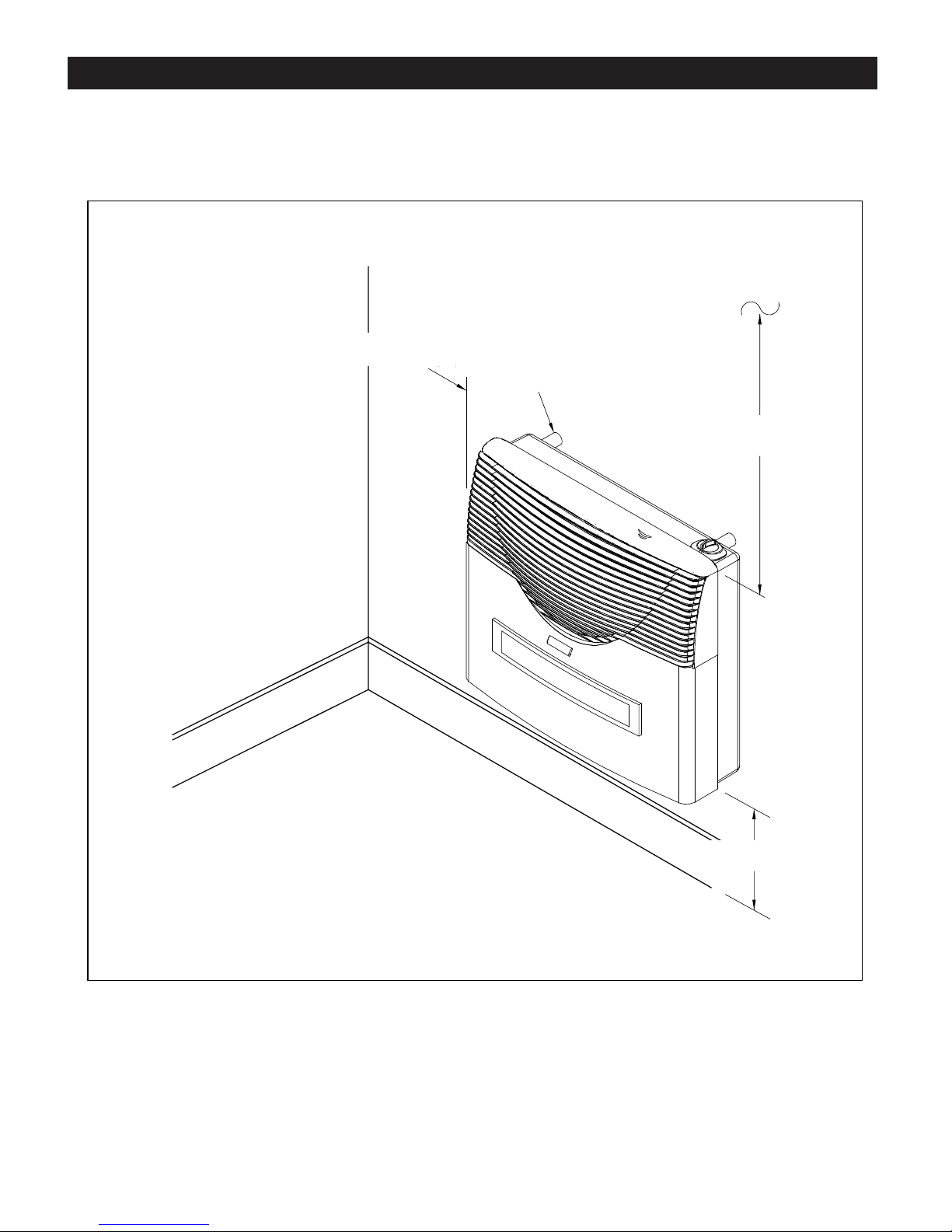
MINIMUM CLEARANCES TO COMBUSTIBLES
15 cm (6 in)
Spacer:
MDV8: 2 cm (25/32 in)
MDV12/20: 3 cm (1-3/16 in)
61 cm (24 in)
Clearances to combustible surfaces:
Rear : MDV8: 2 cm (25/32 in)
MDV12/20: 3cm (1-3/16 in)
Sides : 15 cm (6 in)
Above : 61 cm (24 in)
From floor :
18 cm (7 in) to top of tile, carpeting, etc.
18 cm (7 in)
4
Page 5
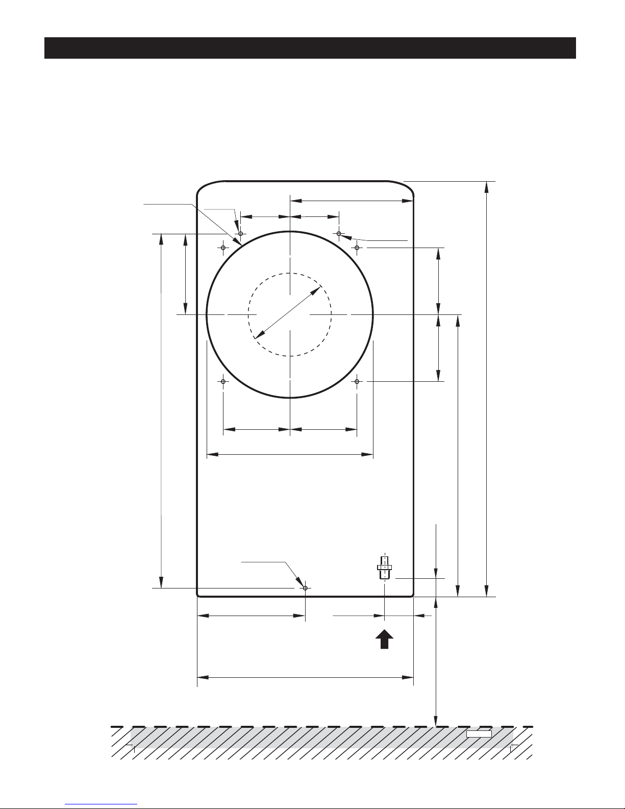
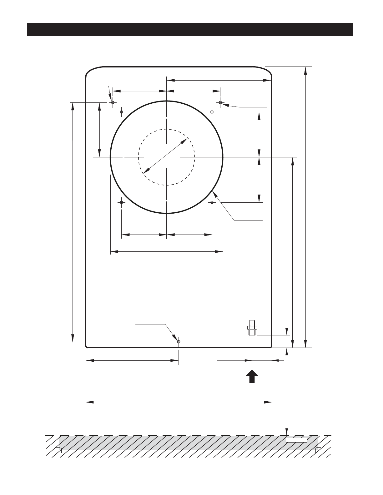
INSTALLATION INSTRUCTIONS
The following diagrams serve as a reference for the installation of your heater with the ventilation provided
with the unit. The template that is provided with the heater should be used. In this case, fold it at the dotted
line 7” below the heater which indicates the floor level, and make it coinciding with the floor level as a
minimum clearance. Also take into consideration the other minimum distances shown. Then fix it to the wall
with adhesive tape.
Model MDV8
Hole for
combustible
wall in both
indoor and
outdoor.
Ø 8 mm
(Ø 5/16”)
68 mm
(2-11/16”)
172 mm (6-3/4”)
68 mm
(2-11/16”)
Ø 8 mm
(Ø 5/16”)
112mm (4-7/16”)
490mm (19-5/16”)
Ø115mm
(Ø4-1/2”)
92mm (3-5/8”)92mm (3-5/8”)
Ø230 mm (9-1/16”)
Ø 8 mm
(Ø 5/16”)
92mm (3-5/8”)92mm (3-5/8”)
575mm (22-5/8”)
390mm (15-3/8”)
25mm (1”)
Floor level (Fold here)
150mm (5-7/8”)
40mm
(1-9/16”)
300 mm (11-13/16”)
5
Gas inlet
3/8”NPT
ecnatsidnuminiM
roolfmorf
180mm (7-1/8”)
ART. 13844
Page 6
Model MDV12
INSTALLATION INSTRUCTIONS
Ø 8 mm
(Ø 5/16”)
112mm (4-7/16”)
490mm (19-5/16”)
110mm
(4-5/16”)
Ø115mm
Ø230 mm (9-1/16”)
(Ø4-1/2”)
92mm (3-5/8”)92mm (3-5/8”)
215mm (8-1/2”)
110mm
(4-5/16”)
Ø 8 mm
(Ø 5/16”)
92mm (3-5/8”)92mm (3-5/8”)
Hole for
combustible
wall in both
indoor and
outdoor.
575mm (22-5/8”)
190mm (7-1/2”)
Floor level (Fold here)
Ø 8 mm
(Ø 5/16”)
380 mm (15”)
40mm
(1-9/16”)
Gas inlet
3/8”NPT
390mm (15-3/8”)
25mm (1”)
ecnatsidnuminiM
roolfmorf
180mm (7-1/8”)
ART. 13012 V2
6
Page 7

Model MDV20
INSTALLATION INSTRUCTIONS
112mm (4-7/16”)
490mm (19-5/16”)
575mm (22-5/8”)
Ø 8 mm
(Ø 5/16”)
Hole for
combustible
wall in both
indoor and
outdoor.
Ø 8 mm
(Ø 5/16”)
245mm
(9-5/8”)
300mm (11-13/16”)
Ø160mm
(Ø4-1/2”)
118mm (4-5/8”)118mm (4-5/8”)
Ø270 mm (10-5/8”)
245mm
(9-5/8”)
Ø 8 mm
(Ø 5/16”)
Ø 8 mm
(Ø 5/16”)
118mm (4-5/8”) 118mm (4-5/8”)
390mm (15-3/8”)
25mm (1”)
110mm (4-5/16”)
12mm (1/2”)
Floor level (Fold here)
390mm (15-3/8”)
660 mm (26”)
7
40mm
(1-9/16”)
ecnatsidnuminiM
roolfmorf
Gas inlet
3/8”NPT
180mm (7-1/8”)
ART. 13066 V2
Page 8

HEATER & VENTILATION INSTALLATION
The ventilation system consists of:
1x External tube (Air intake tube with enamel hood riveted), 1 x Internal tube (Outgoing flue gases)
1x Indoor mounting plate, 1x Outdoor mounting plate
1x Wall thimble (models MDV12 & MDV20 only), 1x Threaded mounting rod, 1x Adjusting nut
˃ Use the template provided with heater to mark wall mount installation and ventilation opening size.
Take into consideration the area indicated for the gas connection.
1. Mark the 5/16” (8mm) mounting holes on wall.
For wooden walls use the wood screws provided
to mount heater to wall. Into drywall or where no
studs are available, drill and insert the anchor plugs
provided into mounting holes.
2. Mark the ventilation tube hole and the mounting
plate screws.
The ventilation must be rectilinear with a slight
downward sloap of 2 degrees towards the
exterior to avoid rain water infiltration.
3. Cut out ventilation opening in wall.
Install the indoor & outdoor mounting plates with
screws provided.
* MDV12 / MDV20 heaters only:
Assemble the wall thimble.
4. Prepare the rear spacers with mounting screws.
* The wallʼs thickness cannot be less than 4-1/2”
(11.5 cm) nor can it exceed 12-5/8” (32 cm).
Tube lengths and threaded mounting rod should
be trimmed to comply to the dimensions as shown
in figure 1.
MDV8 - Total length of ventilation : wall thickness + 15.5 cm (6-3/32’’)
11 cm (4-5/16’’)
MDV12 & MDV20 - Total length of ventilation : wall thickness + 16.5 cm (6-1/2’’)
MDV8 - Total length of internal tube : wall thickness + 11 cm (4-5/16’’)
MDV12/20 - Total length of internal tube : wall thickness + 12 cm (4-3/4’’)
MDV8 : 4,5 cm (1-3/4’’)
MDV8 : 2,5 cm (1’’)
MDV12 / MDV20 : 3,5 cm (1-3/8’’)
MDV12 / MDV20 : 5,5 cm (2-5/32’’)
MDV8
Total length of rod:
Wall thickness + 14,7 cm (5-5/32’’)
To heater
MDV12/20
Total length of rod:
Wall thickness + 15,7 cm (6-3/16’’)
Final Assembly
1. Remove the front cover of the heater by removing
the control knob and the two (2) screws on the top
of the cover. To remove slide the front upwards.
2. After tubes have been cut to length, slide the
tubes and the rod into position on the heater
and adjust with the nut provided until you get a
compact unit. Slide the heater and ventilation
assembly through the hole in wall making sure
spacers are in place on mounting screws, until
the heater reaches the wall.
- For models MDV8 and MDV12, secure to the
wall with the three (3) screws and spacers.
- For model MDV20, secure to the wall with the
four (4) screws and spacers provided.
3. Check that hood protrudes the intended 4-5/16”
(11 cm) from the exterior wall.
4. Seal any imperfections between mounting plate wall and vent hood with putty, making sure that nothing falls inside the
hood as shown in figure 3 on next page.
Fig. 1
MDV8 - Total length of external tube : wall thickness + 13,5 cm (5-5/16’’)
MDV12/20 - Total length of external tube : wall thickness + 14,5 cm (5-11/16’’)
MDV12 : diameter 23 cm (9-1/16’’)
MDV20 : diameter 27 cm (10-5/8’’)
Thimble maximum length : 32 cm (12-5/8’’)
8
Page 9

Minimum wall thickness:
4-1/2’’ (11.5 cm)
Maximum wall thickness:
12-5/8’’ (32 cm)
Fig. 2
VENTILATION INSTALLATION continued
Fig. 3
Fig. 4
IMPORTANT: The appliance’s vent cap should be at least 24 in. (61 cm) from any outside
adjacent or intersecting wall.
IMPORTANT: The appliance’s venting system should be inspected at least once a year and
cleaned if necessary.
IMPORTANT: THE VENT-AIR INTAKE SYSTEM MUST BE PROPERLY INSTALLED TO
INSURE PROPER AND SAFE OPERATION.
9
Page 10

MDV20 66 cm (26’’)
MDV12 38 cm (15’’)
MDV8 30 cm (12’’)
VENTILATION INSTALLATION continued
MDV20
24 cm (9-7/16’’)
MDV12
21 cm (8-1/4’’)
MDV8
20 cm (7-7/8’’)
11 cm (4-5/16’’)
Thimble only for models
MDV12 & MDV20
57,5 cm (22-5/8’’)
Gas valve
Gas
connection
41 cm (16-1/8’’)
See mounting details
18 cm (7’’)
Putty
Mounting Details
Screw
Drywall anchor
Spacer
10
Page 11

VENTILATION INSTALLATION continued
NO NO
contin
NO NO
nitnoc nitnoc
ued...
nitnoc nitnoc
...deu ...deu
...deu ...deu
VENT TERMINAL
V
Clearance above grade, veranda, porch,
= A
deck, or balcony
Clearance to window or door that may be
= B
opened
Clearance to permanently closed window
= C
Vertical clearance to ventilated soffit lo-
= D =
cated above the terminal within a horizontal distance of 2 feet (61 cm) from the center line of the terminal
Clearance to unventilated soffit
= E = E
Clearance to outside corner
= F = F
Clearance to inside corner
= G =
Clearance to each side of center line ex-
= H =
tended above meter/regulator assembly
I
Clearance to service regulator vent outlet
= I I
J
Clearance to nonmechanical air supply in-
= J = J
let to building or the combustion air inlet to
any other appliance
Clearance to a mechanical air supply inlet
= K = K
Clearance above paved sidewalk or paved
= L = L
driveway located on publis property
=
Clearance under veranda,
= M =
balcony
In accordance with the current
1
In accordance with the current
2
porch, deck, or
AIR SUPPLY INLET AREA WHERE TERMINAL IS NOT PERMIETTED
X
Canadian Installation
12 inches (30 cm)
6 inches (15 cm) for appliance
(3 kW), 12 inches (30 cm) for appliance > 10,000
BTU/hr (3 kW) and
36 inches (91 cm) for appliance > 100,000 BTU/
hr (30 kW)
3 feet (91 cm) within a height of 15 feet (4.5 m)
above the meter/regulator assembly
3 feet (91 cm)
6 inches (15 cm) for appliance
(3kW), 12 inches (30 cm) for appliance > 10,000
BTU/hr (3kW) and
36 inches (91 cm) for appliance > 100,000 BTU/
hr (30 kW)
< 100,000 BTU/hr (30 kW),
6 feet (1.83 m)
7 feet (2.13 m) †
12 inches (30 cm) ‡
1
< 10,000 BTU/hr
<100,000 BTU/hr (30 kW),
*
*
*
*
*
< 10,000 BTU/hr
CSA B149.1, Natural Gas and Propane Installation Code
ANSI Z223.1/NFPA 54, National Fuel Gas Code
.
US Installation
6 inches (15 cm) for appliance
(3 kW), 9 inches (23 cm) for appliance > 10,000
BTU/hr (3 kW) and
inches (30 cm) for appliance > 50,000 BTU/hr
(15 kW)
6 inches (15 cm) for appliance
(3kW), 9 inches (23 cm) for appliance > 10,000
BTU/hr (3kW) and
inches (30 cm) for appliance > 50,000 BTU/hr
(15 kW)
3 feet (91 cm) above if within 10 feet (3 m)
.
2
12 inches (30 cm)
< 50,000 BTU/hr (15 kW), 12
*
*
*
*
*
*
*
< 50,000 BTU/hr (15 kW), 12
horizontally
*
*
< 10,000 BTU/hr
< 10,000 BTU/hr
† A vent shall not terminate directly above a paved sidewalk or paved driveway that is located between two single family dwellings
and serve both dwellings.
‡ Permitted only if veranda, porch, deck, or balcony is fully open on a minimum of two sides beneath the floor.
For clearances not specified in
*
ANSI Z223.1/NFPA 54 or CSA B149.1
, one of the following shall be indicated.
(a) A minimum clearances valve determined by testing in accordance with section 2.19.6, or ;
(b) A reference to the following footnote:
“ Clearance in accordance with local installation codes and the requirements of the gas supplier.”
11
Page 12

GAS CONNECTION
NOTICE
A qualified gas appliance installer must connect the heater to the gas supply.
Consult all local codes.
CAUTION
Use new black iron or steel pipe only. Internally tinned copper tubing can be used in some areas
when permitted by local codes. Only use pipe of 1/2" or greater diameter to allow full gas volume
to heater. Excessive pressure loss will occur if the pipe is too small.
A manual shutoff valve, union and plugged 1/8" NPT pressure tapping point must be installed
upstream of the heater as shown in drawing below.
A sediment trap must be installed upstream of the heater to prevent moisture and contaminants
from passing through the pipe to the heater controls and burners. Failure to do so could prevent
the heater from operating reliably.
IMPORTANT:
CHECK GAS TYPE:
Loosen the pipe adapter on the flex tube before installing to the system piping.
Manual shutoff valve
Flexible gas hose
(if allowed by local codes)
From external regulator
Tee joint
Sediment trap
Pipe
nipple
Cap
3’’ minimum
The gas supply must be the same as stated on the heater's rating plate.
If the gas supply is different, DO NOT INSTALL the heater. Contact your dealer for the correct model.
! Connecting directly to an unregulated propane/LPG tank can cause an explosion !
Reattach the front to the unit. Use the same screws removed in the ‘’Final Assembly’’ instructions
on page 8. Reinstall the control knob.
WARNING
12
Page 13

OPERATING INSTRUCTIONS
FOR YOUR SAFETY READ BEFORE LIGHTING
WARNING: If you do not follow these instructions exactly, a fire or explosion
may result causing property damage, personal injury or loss of life.
This appliance has a pilot which can be lit with the equipped piezo ignitor. When lighting the pilot, follow these
instructions exactly.
BEFORE LIGHTING smell all around the appliance area for gas. Be sure to smell next to the floor because propane
gas is heavier than air and will settle at the lowest level.
WHAT TO DO IF YOU SMELL GAS
• Do not attempt to light any appliance.
• Do not touch any electric switch; do not use any phone in your building.
• Immediately call your gas supplier from a neighbor's phone. Follow the gas supplier's instructions.
• If you cannot reach your gas supplier, call the fire department.
Use only your hand to push in or turn the gas control knob. Never use tools. If the knob will not push in or turn by hand,
don't try to repair it, call a qualified service technician. Force or attempted repair may result in a fire or explosion.
Do not use this appliance if any part has been under water. Immediately call a qualified service technician to inspect the
appliance and to replace any part of the control system and any gas control which has been under water.
LIGHTING INSTRUCTIONS
STOP ! Read the
1.
Press the knob lightly and turn clockwise to the “OFF” position.
2.
Wait five (5) minutes to clear out any gas. If you smell gas, STOP! Follow
3.
the safety information above on this page. If you donʼt smell gas, go to the
next step.
Find the pilot by looking through the viewing window on the front of the unit.
4.
Press the knob down lightly and turn counterclockwise to the
5.
Position. Press down and hold.
Press the Piezo Ignition button to light the pilot. Repeat this operation with the
6.
knob pressed down until the pilot is lit. When the pilot lights, continue pressing
for another 10 seconds. Release the knob. If the pilot goes out, repeat steps
1 through 6.
If the knob does not pop up when released, stop and immediately call your
service technician or gas supplier.
If the pilot will not stay lit after several tries, turn the gas control knob to
call your service technician or gas supplier.
Press down and turning the control knob counterclockwise to the
7.
desired temperature. The temperature can be regulated between HI and LO
capacity, according to the indicated scale marked on the knob.
safety information above on this page.
”toliP“ ”toliP“
FFO FFO
OFF and
FFO FFO
LO
OFF
Ignition button
HIPilot
When the heater is first started after installation or if the heater has not been used for a long period of time, there is a
normal delay while air is being purged from the gas line until gas arrives to heater. In this case, maintain pressure on the
knob at the “Pilot” position for 30-40 seconds while pressing the piezo button every 4-5 seconds to avoid accumulation of
gas, or until the pilot lights.
TURNING OFF GAS TO APPLIANCE
When the heater is not to be in use for a long period of time or for servicing, turn the control knob clockwise to
the
position and close the main gas supply valve.
FFO FO
13
Page 14

MAINTENANCE INSTRUCTIONS
As with all fuel burning appliances, it is important to conduct periodic maintenance functions that will allow for continued
safe, efficient operation of the unit. We suggest that before every heating season, or at least once a year, conduct
the following minimum service functions.
STEP 1: The gas supply should be turned OFF at the shutoff valve in the supply line leading to the appliance or at the
gas source. The gas to the unit should then be disconnected so the unit can be removed from the wall.
STEP 2: Remove the front cover by removing the control knob and the two(2) screws on the top of the front. Then slide
the front upwards.
STEP 3: Carefully examine the interior of the vent pipe. If you notice any blockages or obstruction that was not part of
the unit when it was installed. Clean the pipes and prepare them for reattachment to the unit.
The vent system should be inspected periodically, or at least once a year and cleaned if necessary. If removal of the
venting is required, follow the instructions in the “Ventilation Installation” section of this manual for reassembly.
STEP 4: Look inside the openings of the rear of the unit and check for foreign materials. Remove any objects which
may block or obstruct the free flow of combustion and ventilation air.
STEP 5: Visually check the pilot and the main burner for signs of excessive dirt or debris through the heat exchanger
front glass. If you find any of these, follow the directions below to reach the components to clean, otherwise continue
to the next step.
To Remove Pilot: Find the pilot. Loosen the head of thermocouple, disconnect the pilot gas supply line, (only on the
side of the pilot, not on the valve side). Remove the two (2) M4 screws that hold the pilot in place. Clean with a vacuum
cleaner or use a can of compressed air.
To Remove Burner: Loosen the gas line from the burner (on the right side of the unit). On the left side of the unit,
unscrew the nut that holds the burner in place. Then remove the burner. Clean with a vacuum cleaner or use a can of
compressed air.
Note: You can remove the main burner-pilot assembly if you don’t unscrew the M4 screws that hold the pilot to the burner.
Before reinstalling the assembly, check the ceramic fiber sealing gasket. If it is damaged or worn, replace with a new
gasket available from your dealer.
STEP 6: Reassemble the unit back to its original state and mount the unit to the wall. Properly reassemble and reseal
the vent-air intake system.
STEP 7: Reconnect the gas supply and check for leaks using a soapy water solution that you apply to all gas connections.
Bubbles on any of the joints indicate a leak is present and must be repaired. Turn off the gas when making such repairs.
Check to make sure that the piezo ignitor still lights the pilot.
STEP 8: While the main burner is ON, Check the flames to verify that they are burning a clean blue color.
(See Fig. 5, 6 & 7 on next page).
Note: After maintenance, the first few minutes of the heater operation will probably have some yellowish flying traces in
the flame due to the burning of particles left behind during the cleaning operation.
** Liquid Propane will have some evidence of yellow tips on the flame.
Any safety screen or guard removed for servicing an appliance must be replaced prior to operating the appliance.
Before completing your periodic maintenance check, ensure the heater area is kept clean
and free from combustible materials, gasoline and other flammable vapors and liquids.
Also,check to see that the flow of combustion and ventilation air around the vent cap on the
outside of the structure is not obstructed.
14
Page 15

Fig. 5
Correct Flame Pattern
Fig. 6
Correct Flame Pattern
Fig. 7
Incorrect Flame Pattern
15
Page 16

PARTS LIST MDV8
P
NATURAL (118)
PROPANE (85)
ITEM
DESCRIPTION
QTY
16
Page 17

PARTS LIST MDV12 & MDV12V (View)
NATURAL (137)
PROPANE (104)
P
ITEM
DESCRIPTION
QTY
17
Page 18

PARTS LIST MDV20 & MDV20V (View)
PROPANE
NATURAL (178)
P
(131)
ITEM DESCRIPTION
QTY
18
Page 19

MARTIN ® LIMITED WARRANTY FOR MDV SERIES GRAVITY VENT GAS HEATERS
Bismar incorporated warrants material and workmanship of your new Martin ® Gravity Vent heater against defects. This Limited
Warranty is effective from original date of purchase and applies to the original purchaser of the heater provided it was purchased
through an authorized Martin ® products dealer. This factory warranty is non-transferable and may not be extended in any way by
our representatives. This warranty covers new products only which have not been altered, modified nor repaired since shipment
from the factory.
This LIMITED WARRANTY applies to normal residential use only.
LIMITED WARRANTY APPLICATION AND COVERAGE :
- 1 year coverage from defect and/or workmanship on all parts.
- Original owner: Lifetime replacement coverage of the combustion chamber: (against deterioration of weld integrity or defects
and castings).
- Not covered: All labour costs.
Shall your heater or a component be defective, contact our customer service and make sure you have the following information
necessary to your warranty claim treatment:
- Bill of sales and name of dealer. Serial number and model number as indicated on the rating plate on back of unit.
Nature of the defect and any relevant information.
CONDITIONS AND EXCLUSIONS
This appliance must be installed by a licensed, authorized service technician or contractor. The installation must be done in
accordance with the installation instructions provided with the product and all local and national building and fire codes.
Any defect or damage caused by any alteration or the use of unauthorized parts or others than original parts void this warranty.
This Limited Warranty does not cover any scratches, corrosion, warping or discoloration caused by over firing or exposure to
chemicals or ones in the environment or the use of abrasive and/or chemical cleaners. This warranty does not cover damages
caused by misuse, alteration, neglect, improper installation, lack of maintenance, accidents or failure to perform normal and
routine maintenance and inspection, accident during transportation, power failures, downdrafts, or venting problems.
This warranty is limited to the repair or replacement of parts at no charge which prove to be defective under normal domestic
use and service and which on examination shall indicate to Bismar’s satisfaction they are defective. Only original parts from the
manufacturer must be used for repair or maintenance. The manufacturer may require the return of defective part or that digital
pictures be provided to support the claim.
Defective parts will be replaced free of charge during the warranty coverage from date of purchase with reasonable proof of
purchase and date. Parts returned for investigation must be shipped “Prepaid”. Parts under warranty will be returned to the
purchaser “Prepaid”. This warranty does not cover labor charges for replacement or repair of parts under the warranty coverage
of warranted parts. No labour costs wether during part warranty coverage, or travel expenses, is covered.
Repair work covered by the warranty, executed at the purchaser’s domicile by an authorized qualified technician requires the prior
approval of the manufacturer. Any service call related to an improper installation is not covered by this warranty.
There are no other expressed warranties except as set forth herein and any implied warranties of merchantability and fitness in
duration to the period of coverage of this expressed written Limited Warranty.
Bismar will not be liable for any special or indirect cause or consequence related in connection with the sale, installation, use,
damage, return or replacement of its equipment, and no such representations are binding on Bismar incorporated.
Some states, provinces or jurisdictions do not allow the exclusion or limitation of incidental or consequential damages or limitations
on how long an implied warranty lasts, so the above limitations or exclusions may not apply to you. This warranty gives you specific
rights, and you may also have other rights that may vary from state or province to province.
If unit or defective parts are required to be returned, please contact our customer service for a return
authorization number prior to ship. Any merchandise shipped to our plant without an authorization will be
refused automatically and returned to sender. Refer to coordinates on front page of this manual.
19
rev. 6/16
 Loading...