

Page 1
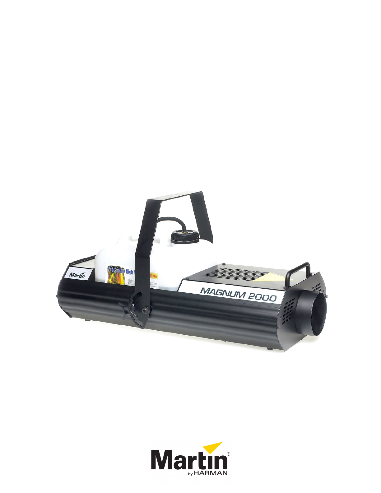
Magn um 2000
user manual
Page 2
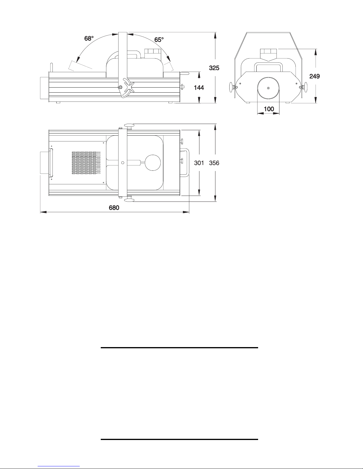
Figure 1: Dimensions in mm
©1995, 2000 Martin Professional A/S, Denmark.
All rights reserved. No part of this manual may be
reproduced, in any form or by any means, without
permission in writing from Martin Professional A/S,
Denmark.
Printed in Denmark.
P/N 35000038, Rev.
2
C
Page 3

NTRODUCTION
I
FEATURES
The Magnum 2000 is a high performan ce micro-controller based smoke
machine that features:
• Specially designed heating element for long life and reliability
• High press ur e pump
• Variable smoke output
• Remote control un it wi th auto -tim er a nd memo ry fun ct ion
• 0-10 V control input
• Slave output for control of multiple units from a single remote control
• 9.5 liter (2.5 gallon) internal tank
• Electronic and mechanical overheating protection with manual rese t
• Mounting bracket and carrying handles
• Non-toxic fog-fluid
1
Introduction 3
Page 4

SAFETY
This product is for professional use only.
usage, read this manual before powering or installing the device, follow the safety
precautions listed below and observe all warnings in this manual and printed on the
device. If you have questions about how to operate th e device safely, please contact
your Martin dealer or call the Martin 24-hour service hotline at +45 70 200 201.
• Keep the output nozzle at least 60 cm (24 inches) away from people and obj ects.
• Never point the output at people’s heads or place your hand over the nozzle.
• Disconnect the device from AC power before refilling the fluid tank or servicing.
• Use specified fog fluid only.
• Always ground (earth) the device electrically. Use only a source of AC power that
complies with local building and electrical codes and has both overload and groundfault protection.
• Do not expose the device to rain.
• Never operate the smoke machine if it is dam aged or if parts are missing.
• Never attempt to bypass the thermostatic switch or fuses. Always replace defective
fuses with ones of the specified type and rating.
It is not for household use. For safe
• Allow the device to co ol be fore handling.
• Refer all service not described in this manual to a qualified technician.
• Do not install the smoke machine directly over people.
• When suspending the device above ground level, verify that the structure can hold
at least 10 times the weight of all installed devices. Use an approved means of
secondary attachment such as a safety cable.
• Block access below the work area whenever installing or removing the device.
4 Introduction
Page 5

ET UP
S
Your Magnum 2000 pac kage comes complete with the following items:
• Magnum 2000 smoke machine with remote control unit
• 5 meter (16.5 ft) XLR/XLR cable for remote control
• Adaptor-cap with fluid filter for fluid tank
• Users guide
Warning! Before attemptin g any of the following ensure th at the machine
is disconnected from mains power.
FITTING THE MAINS PLUG
2
Warning! For protecti on from fire an d elec tric shock, th e fixtur e must be
grounded (earthed).
The Magnum 2000 is delivered from the factor y without a plug o n the main s
lead. You will have to fit a suitable plug (one that fits your local wall outlet) before
you can connect the machine to the mains. T he double isolated mains lead o n the
Magnum 2000 contains three wires. Connect the brown wire to the LIVE pin,
the blue wire to the NEUTRAL pin, and the Yellow/Green wire to the EARTH pin
(ground).
INSTALLATION
The Magnum 2000 may be placed on a flat surface or suspended by means of a
rigging clamp (not included) fastened through the 13 mm (0.5 inch) hole in the
mounting brac ket. The adjustable brack et a llo ws you to t urn and/o r tilt t he ma chine.
Warning! DO NOT install direct ly above or wi thin 60cm ( 24 inches) o f
ople.
pe
Warning! Use a safety cable for s econdar y at tachmen t.
Set up 5
Page 6

FOG FLUID
Martin fog f luid comes in disposable containers that fit the smoke machine.
Impor tant! Use Mart in or Je m “Pro-Smoke ” fog fluid only. Other fl uids may
clog the heating element or spit from the nozzle.
To install the fluid tank
1 Place the fluid tank in the Magnum 2000 as shown on page 2.
Remove the container cap and screw on the tank adaptor cap. Verify that the
2
tube (with fluid filter) reaches the bottom of the tank.
3 Connect the fluid tube to the fluid outlet of the tank adaptor cap.
6 Set up
Page 7

PERATION
O
For optimum performance from your Magnum 2000:
• Keep the machine and the remote cont rol unit away from damp rooms or wet
conditions.
• Never operate the machine without fluid in the tank, as this may harm the pump
system.
• Use clean fluid to avoid clogging of the heating element and damage to the pu mp.
• Use Martin fog f luid. This flui d is non- toxic, wa ter-based and speciall y designed
for Martin smoke machines. Jem “Pro-Smoke” fluids may be substituted.
(REMOTE) CONTROL UNIT
The control unit is secured to t he back panel by two thumbscrews. It may be
removed for remote control and placed i n a rack or on a table.
3
To remove the control unit
1 Unscrew the thumbscrews on either side of the control unit and pull it out of
the control unit well.
2 Use the included cable to connect either one of the 3-pin outputs on the control
unit to the 3-pin input inside the control unit well.
Either of the control unit’s outputs may be used, but not both. To connect additional
machines, use the “Sl ave output” on the rear panel of the smoke machine.
POWER
To enable the heater circuit, si mply tu rn t he k nob o n the co ntro l u ni t c loc k wise un til
the POWER LED lights.
Operation 7
Page 8

STATUS
The three LEDs on the rear panel of the smoke machine indicate the machines
status.
POWER (red):
HEAT (red)
slowly as the heating cycle nears the en d. It turns off when the heat ing el em ent has
reached maximu m temp eratu re. T he h eati ng cycle fo r a c old ma chin e takes 8 to 10
minutes.
READY (green)
on simultaneously as smoke production is possible when the machine is heating.
There is power to the heater.
: The machine is heating. The LED flashes rapidly and then more
: Ready to produce smoke. The HEAT and READY LEDs can be
MANUAL OPERATION
As soon as the green READY LED turns on, you can make smoke by pressing the
Smoke button on the control unit. The output level can be adjusted using the Smoke
output knob.
Though the fluid pump stops when you release the Smoke button, smoke emission
will continue for another few seconds becau se the fluid in the hea ting element is
under pressure.
AUTO-TIMER
The auto-timer allows you to program output duration and level at repeatable
intervals. The maximum programmable in terval (output duration + pause) is
approximately 1 hour.
The auto-timer sequence is stored in the smoke machine’s memory and is not
cleared when disconnec tin g th e machi ne from mains power. When switched on, the
machine will execute the aut o-timer sequence as so on the machine is ready.
Adjusting the smoke output potentiometer does not override the stored auto-timer
level. You can still produce smoke manual ly and, if this level is higher than the
stored level, it will take precedence.
To set the auto-timer
1 Adjust the Smoke output knob to the desired level.
2 Press the smoke button for the desired output duration.
3 Wait for the desired pause time and then press the timer store button.
8 Operation
Page 9

4 To terminate the auto-timer sequence, press the timer store button for 5
seconds. This clears the memory.
For example, to prog ram 15 seco nds of smoke every 2 minutes, press the smoke
button for 15 seconds, wait 1 mi nute and 45 seconds, and then press timer s tore.
0-10 V OPERATION
Operation via a 0-10 volt signal is similar to operation via the remote control unit.
Unplug the remote control uni t and connect your ana log source to the XLR control
input inside the control unit well. Verify that GND (ground) on you r analog source
connects to pi n 1 on th e XLR contr ol in put and t hat the +0- 10V outp ut con nects to
pin 3.
The analog control levels are shown below.
Voltage Function
0 - 1.0 V Standby
1.0 - 2.5 V Heater power on
2.5 - 9.5 V Smoke emission, increases with voltage
9.5 - 10.0 V Timer store
MULTIPLE MACHINES
Whether you operate your Magnum 2000 via the control unit or a 0-10 volt
source, you can command additional machines through the XLR “slave output” on
the back panel. Connect the slave output on the first machine to the control input
(located inside the control unit well) of the next machine. Continue by similarly
connecting as many machines as desired output to input.
All machines connected in this manner will pro duce smoke at the same time and
output level as the first machine.
Operation 9
Page 10

ASIC SERVICE
B
TROUBLESHOOTING
4
No light in the POWER LED on rear
panel.
No light in the POWER LED on the
control unit.
Pressing the smoke button activates
the pump but no smoke is produced.
The machine indicates heating but the
READY LED never lights.
In case of other failures, contact a Martin service technician.
Check the mains plug. Check the
fuse.
Is the remote control unit properly
connected? Check XLR/XLR cable.
Check that the fluid filter reaches the
bottom of the tank. Check that the
fluid tube is connected to the inlet on
the machine.
Reset the thermo-switch as described
below. If the problem persists then
consult your Martin dealer.
FUSE
230 V model: Use a 10A slow-blow fuse.
115 V model: Use a 15A slow-blow fuse.
To replace the fuse
Warning! Before attemp ting any of the following ensur e th at the m achine
is discon nected from mains power.
1 Remove the fluid tank from the machine.
2 Remove the Philips screws that secure top-cover at the back of the machine.
3 Slide the cover forwards until the circuit board (PCB) is accessible.
4 Locate on the left hand-side of the PCB fuse "F1".
5 Replace the fuse with a new one (T 10 A at 230 V, T 15 A at 115 V).
6 Re-assemble the device before connecting to the mains.
10 Basic servic e
Page 11

THERMO-SWITCH
The Magnum 2000 has an over-heat switch (ther mo-switch) that interrupt s
power to the heating element shoul d it reach a temperature above normal.
The thermo-switch must be reset manually after it has been activated. This reset is
performed by pressing the plastic button on top of the switc h.
If the thermo-switch activates repeatedly, contact your Marti n dealer for service.
To reset the thermo-switch
Warning! Before attemptin g any of the following ensure th at the machine
is disconn ected from mains power and cool ed down.
1 Remove the fluid tank from the machine.
2 Remove the two Philips screws that secure the top cover over the heating
element.
3 Slide the cover backwards until the thermo-switch becomes accessible. The
thermo-switch is located on the mid, left hand side of the heating element with
two wires attached.
4 Press the plastic button on the thermo-switch to reset it.
5 Reassemble the machine before connecting to the mains.
Basic servic e 11
Page 12

PECIFICATIONS
S
Dimensions: See figure 1
Weight (empty tank): 13 Kg (28.5 lb)
5
AC-voltage - 230 V model:
AC-voltage - 115 V model:
AC-frequency:
Power consumption: 1700 W
Maximum fluid consumption: 0.2 l/min
Tank capacity: 9.5 l (2.5 gall)
Warm-up time: 8 - 10 min
Fuse: 10 AT at 200 - 260 V
Overheat protection: Electronic / Mechanical (with manual reset)
200 - 260 V
100 - 130 V
50 / 60 Hz
15 AT at 100 - 130 V
 Loading...