

Martin MAC Aura XB Service Manual
MAC Aura XB
SERVICE MANUAL
Revision A, 05-15-2017
Service manual
2 of 27MAC Aura XB - Revision A, 05-15-2017
Table of contents
General information ............................................................................................................................................ ...3
Safety instructions .................................................................................................................................................................................3
Tools ........................................................................................................................................................................................................3
Spare parts ..............................................................................................................................................................................................4
Product information ...............................................................................................................................................................................4
Troubleshooting .....................................................................................................................................................6
Overview of error codes .........................................................................................................................................................................6
Wiring diagram ........................................................................................................................................................................................8
Repair and maintenance ..................................................................................................................................... ...9
Head .........................................................................................................................................................................................................9
Replacing the head fan .......................................................................................................................................................................................... 9
Replacing the main LCD display ........................................................................................................................................................................ 10
Replacing the thermo switch .............................................................................................................................................................................. 11
Replacing the front lens ...................................................................................................................................................................................... 12
Replacing the diffuser plate ................................................................................................................................................................................ 14
Replacing the secondary pixel board ................................................................................................................................................................ 15
Replacing the zoom motors ................................................................................................................................................................................ 15
Replacing the light rods ...................................................................................................................................................................................... 15
Replacing the primary pixel board ..................................................................................................................................................................... 16
Yoke .......................................................................................................................................................................................................17
Removing the yoke cover .................................................................................................................................................................................... 17
Replacing the tilt sensor PCB ............................................................................................................................................................................. 17
Adjusting the tilt timing belt ................................................................................................................................................................................ 18
Replacing the tilt positioning sensor PCB ........................................................................................................................................................ 18
Replacing the pan reset sensor PCB ................................................................................................................................................................. 18
Replacing the pan positioning sensor PCB ...................................................................................................................................................... 19
Replacing the yoke bracket ................................................................................................................................................................................. 19
Base .......................................................................................................................................................................................................21
Replacing the base fan ........................................................................................................................................................................................ 21
Replacing the PSU ............................................................................................................................................................................................... 22
Maintenance ....................................................................................................................................................... ...25
Cleaning the product ............................................................................................................................................................................25
Conditions .............................................................................................................................................................................................25
Maintenance schedule .........................................................................................................................................................................26
Service manual
3 of 27MAC Aura XB - Revision A, 05-15-2017
Figure 1: Safety instructions
Figure 2: Tools
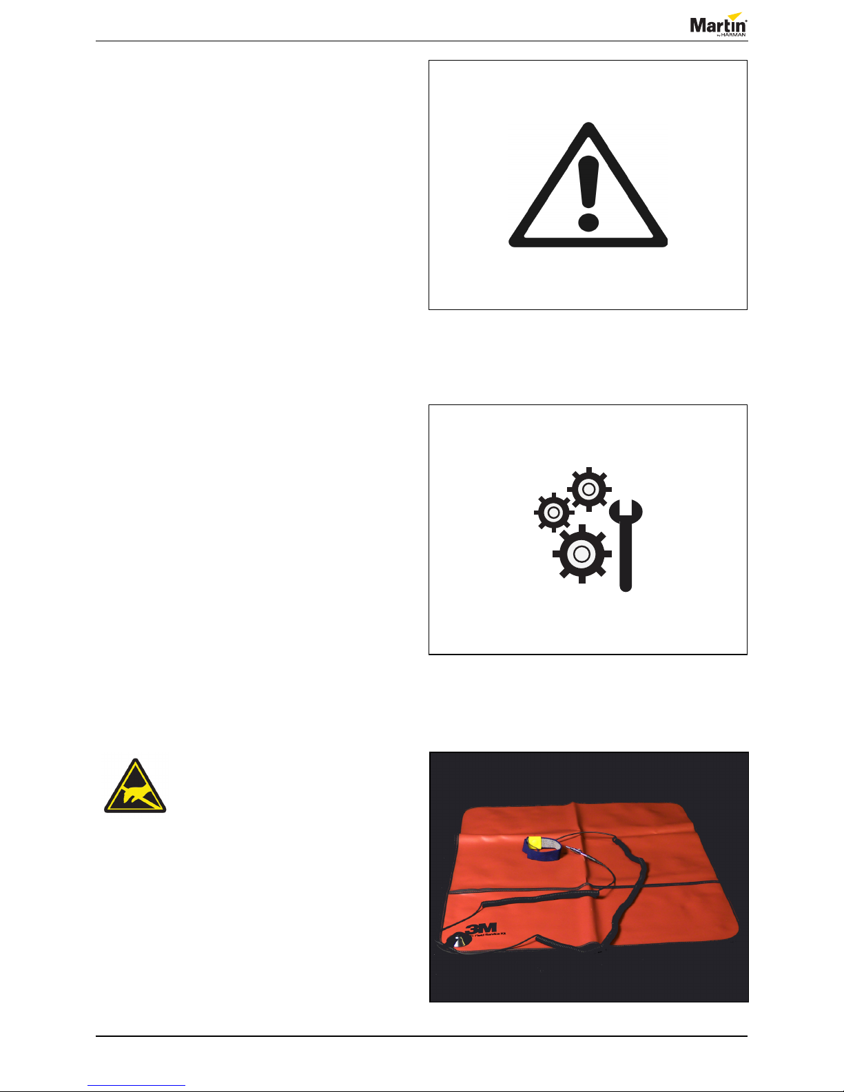
Figure 3: ESD mat and wristband
General information
This service manual contains information about how to
service MAC Aura XB.
Safety instructions
Before you carry out service work, read this document.
Installation and service work must comply with local
regulations and accepted codes of good practice.
Observe the safety instructions in the user manual for
the product.
Tools
Make sure that the tools below are available before you
start working on the product:
• Torx 9
• Torx 10
• Torx 20
• Small atheaded screwdriver
• 5.5 mm hex socket screwdriver
• 7 mm hex socket screwdriver
• Gloves
• ESD mat and wristband.
Take the necessary precautions
to prevent static electricity from
damaging the product during
modication or repair.
Service manual
4 of 27MAC Aura XB - Revision A, 05-15-2017
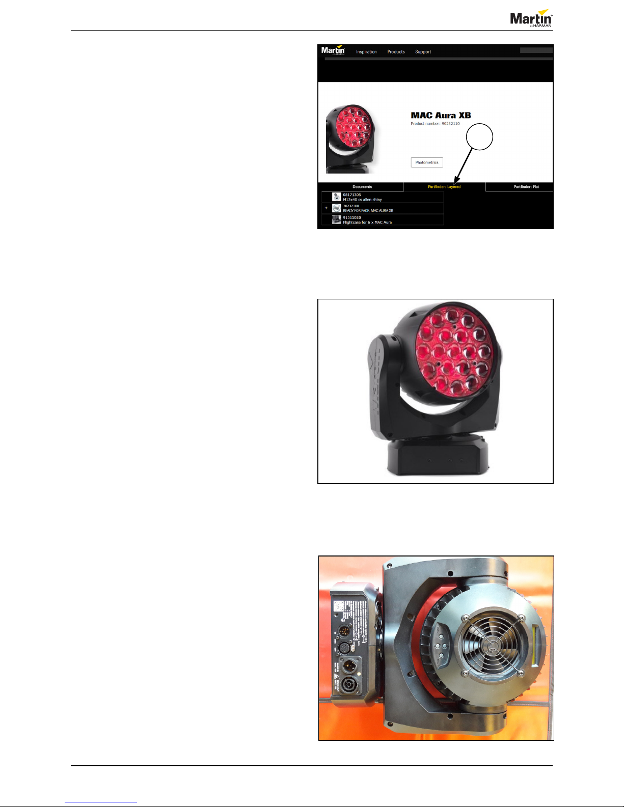
Figure 4: PartFinder: Layered
Figure 5: Yoke and head construction
Figure 6: Lens pointing towards the table
Spare parts
For an overview of the spare parts and spare part
numbers of MAC Aura XB, refer to martin.com.
1. Login with your user login details.
2. Search for “MAC Aura XB”.
3. Clik “Partnder: Layered” (1).
Product information
Before you start servicing the product, notice that the
yoke covers have great impact on the strength and
stability of the yoke and head construction.
Once you have removed the yoke cover, we
recommend that you pay special attention to the forces
that the yoke bracket is exposed to.
We highly recommend that you place the xture with
the lens pointing towards the table. To avoid scratching
the lens, we recommend that you place a soft cloth
under the head of the xture.
1
Service manual
5 of 27MAC Aura XB - Revision A, 05-15-2017
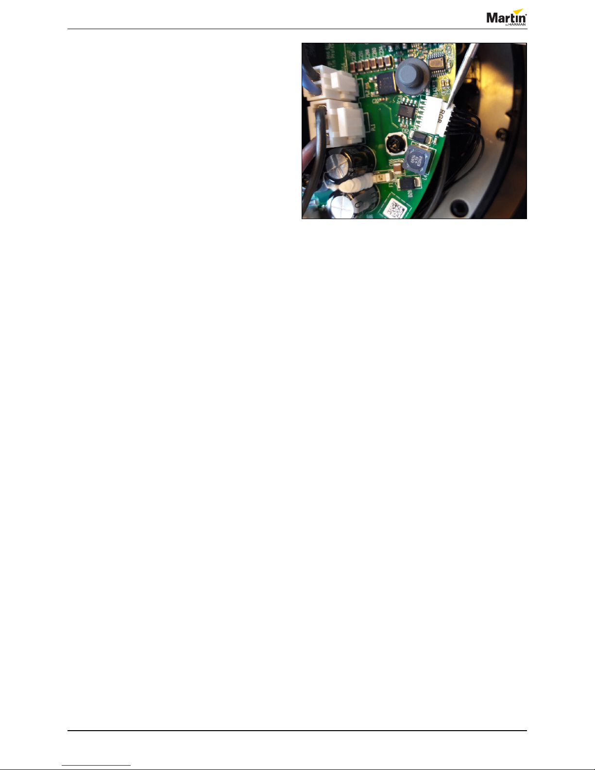
Figure 7: Loosening the connectors
Most of the wires that are connected to the mainboard
are small. Use a small atheaded screwdriver to loosen
the connectors.
NOTE! Never disconnect the connectors by pulling the
wires.
Service manual
6 of 27MAC Aura XB - Revision A, 05-15-2017
Troubleshooting
Overview of error codes
Error message Symptom Cause Remedy
MAIN TMP SEN ERR The LEDs cannot be turned on. The main PCB is too hot. Replace the fan.
The communication wire between the main
PCB and LED PCBs is faulty.
Replace the wire harness (P/N 11860396).
The wire harness goes from connector PL16 to
PL39 on the LED PCB. See gure 8.
The main PCB is faulty Replace the main PCB.
BEAM TMP SEN ERR The Beam LEDs cannot be turned on. The communication wire from the main PCB
to the Beam LED PCB is faulty
Replace the wire harness (P/N 11860396).
The wire harness goes from connector PL16 to
PL39 on the LED PCB. See gure 8.
The Beam LED PCB is too hot. Replace the Beam LED PCB.
The main PCB is faulty. Replace the main PCB.
AURA TMP CUT OFF The LEDs cannot be turned on. The communication wire from the main PCB to
the Aura LED PCB is faulty.
Replace the wire harness (P/N 11860396).
The wire harness goes from connector PL16 to
PL39 on the LED PCB side.
The Aura LED PCB is too hot. Replace the Aura LED PCB.
The main PCB is faulty. Replace the main PCB.
Pan Sensor Error The xture fails the reset sequence.
The reset sounds wrong.
The pan position is faulty.
The absolute position is not found. Check the sensor ( gure 30, PR), the wiring
and replace the sensor, if necessary.
The belt is worn out or is not properly
tightened.
Tighten the belt, or replace it, if necessary.
The motor is faulty. Check the motor and the motor cable, replace
them if necessary. Replace the main PCB.
Tilt Sensor Error. The xture fails the reset sequence.
The reset sounds wrong.
The tilt position is faulty.
The absolute position is not found. Check the sensor ( gure 30, TR), the wiring
and replace the sensor, if necessary.
The belt is worn out or is not properly
tightened.
Tighten the belt, or replace it, if necessary.
The motor is faulty. Check the motor and the motor cable, replace
them if necessary. Replace the main PCB.
FBEP or FBET The xture fails the reset sequence.
Pan or tilt continue to move until timeout.
The reset sounds wrong.
The pan or tilt position is faulty.
The screw on the tacho wheel is not tight. Tighten the screw.
The teeth of the tacho wheel are damaged. Replace the tacho wheel.
The wire is faulty. Replace the wire.
The sensor is faulty. Replace the sensor.
The main PCB is faulty. Replace the main PCB.
The belt is damaged or not tightend properly. Tighten the belt and replace it, if necessary.
Voltage error Reset is OK but an error is displayed.
The Aura LEDs are OK but the beam LEDs will
not turn on.
The thermal switch in the LED heat sink is
open circuit.
Check the thermal switch ( gure 15) and
replace it, if necessary.
+88 VDC is not supplied to the main PCB. Check the +88 VDC wire. Replace the wire
harness (P/N 11860395), if necessary. See
gure 8.
EFFECTS TOO COLD The ambient temperature is too low. Leave the xture powered on to warm it up or
move the xture to a more warm location.
Update the rmware.
Fan error The fan does not work.
The LEDs will not turn on.
The fan is faulty. Replace the fan.
The fan driver is faulty. Replace the main PCB.
BEAM CALIB ERR The xture reset is OK.
The LEDs work.
The Beam colors do not match other products.
Calibration values cannot be read from the
Beam LED PCB.
Check the communication wires from the
mainboard to the Beam LED PCB and replace
the Beam LED PCB, if necessary.
AURA CALIB ERR The xture reset is OK.
The LEDs work
The Aura colors do not match other products.
Calibration values cannot be read from the
Aura LED PCB.
Check the communication wires from the
Beam LED PCB to the Aura LED PCB and
replace the Aura LED PCB, if necessary.
The xture is not working
The xture does not power up or reset
The fuse is blown. Replace the fuse.
The PSU is faulty. Replace the PSU.
The main PCB is faulty. Replace the main PCB.
LED issue The LED pixel PCB or the main PCB is faulty. Replace the LED pixel PCB or the main PCB.
The xture does not show the correct color/
have the same intensity.
The xture does not show the correct color.
The xture does not have the same intensity.
The xture does not have the same intensity.
The xture does not show the correct color.
Service manual
7 of 27MAC Aura XB - Revision A, 05-15-2017
Error message Symptom Cause Remedy
DMX issue
The xture does not function according to the
DMX channels
XLR sockets are faulty. Replace the XLR socket.
The wire set is faulty. Replace the wire set.
The TX/RX chip is faulty. Replace the TX/RX chip.
The main PCB is faulty. Replace the main PCB.
Color differences
The xture does show the same colors as
other xtures.
The mode is incorrect - RGB, EXTENDED
or RAW
Change the mode.
The calibration values on one of the boards
are corrupt or missing.
Replace the pixel board.
The main PCB is defective. Replace the main PCB.
Display issues
The display is not active or some pixels are
missing.
The ribbon cable connection is faulty. Replace the ribbon cable.
The display is faulty. Replace the display.
The main PCB is faulty Replace the main PCB.
Zoom issues
The beam angle is not the same as the other
xtures’.
One or more of the three zoom motors are
faulty.
Replace the motor.
The wire connection is faulty. Replace the wire set.
The main PCB is faulty. Replace the main PCB.

Service manual
8 of 27MAC Aura XB - Revision A, 05-15-2017
8 of 27
Wiring diagram
© 2017 Martin Professional ApS
Martin™ General Technical Specification apply to this item
Confidential
Page 1 of 1
MAC Aura XB
1
1
SMPS:
88V
24V
5V
Pwr. ON LED
DMX Interface
PFC:
Mains Fuse
Mains Filter
5V
PAN
M
TILT
M
400VDC
5,0VDC
5,0VDC-Isol.
DMX IN DMX OUT
88V, 24V
5V 5V 5V
4
FAN2
PL14
PL3
PL19
DMX
24V
88V
PL22
PL7 PL17 PL6 PL15 PL8
GreenRedBlue
LCD
PL13 PL12 PL11
PL1
PL39
LED:
Red and Green
EEPROM /
Temp
PL16
4
uCtrl.
Motor
LED Drv.
RGB Drv.
EEPROM
Temp. Sens.
LCD, Key's x4
FAN Ctrl.
24V, 88V
13.6V, 5V
4
4
3
4
DMX
Mains IN
PL2
PL7
PL6 PL8
PL1
PL3
RGB Leds
EEPROM / Temp
LED String 1,2,3,4
Zoom Motors
EEPROM / Temp
PL9
White
PL14
LED:
Blue and White
PL2
PL45
PL41
4
4
4
PL44
PL43
PL42
4
4
4
PL39
4
PL19
6
RGB
PL18
3
FAN1
PL5
ThermoSwitch
2
PL2
PL1
1
1
2
2 1
Opto Sensor TILT POS
Primary P ixel Board
Main Board
Opto Sensor PAN POS
Secondary P ixel Board
Heatsink
Opto Sensor PAN RESET
Display
SMPS/PFC PCB
Opto Sensor TILT RESET
PM TM PR PP TR TP
1
ZM
LED IO
ZM
ZM
ZM
ZM
ZM
ZM
4 4 3 4
LED IO
LED IO2
ZM
EEPROM /
Temp
LED IO2
RGB
PR PP TR TP
4
4
4
2
2
2
2
2
Figure 8: Wiring diagram, MAC Aura XB Hybrid
Service manual
9 of 27MAC Aura XB - Revision A, 05-15-2017
Repair and maintenance
Head
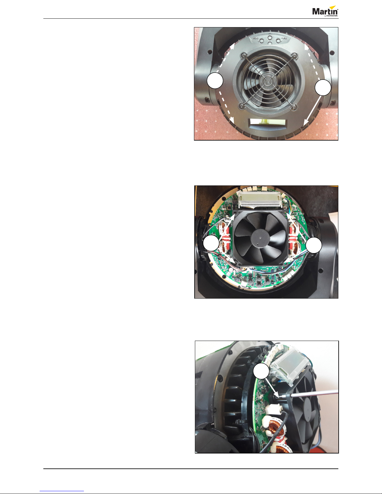
Replacing the head fan
1. Remove the four TX20 screws (1) that hold the
rear cover.
2. Remove the rear head cover.
3. Remove the four TX20 screws (2) that hold the
fan.
4. Remove the fan.
5. To replace the fan, follow the procedure in reverse
order.
Figure 9: Remove rear cover
1
1
Figure 10: Removing the screws
2
2
Figure 11: Removing the screws
2
 Loading...