

Page 1

MAC 575 Krypton Low-Noise Upgrade Kit Installation Guide – Page 1 of 46
MAC 575 Krypton™ Low-Noise
Upgrade Kit Installation Guide
Introduction
This Installation Guide explains how to install the MAC 575 Krypton Low-Noise Upgrad e Kit to convert a
standard MAC 575 Krypton to a Low-Noise model.
The MAC 575 Krypton Low-Noise Upgrade Kit has part number P/N 50300514.
For the latest documentation and information abo ut this and all Martin Pro fessional prod ucts, please visit
the Martin website at www.martin.com.
Warning! Read and follow the safety precautions in the MAC 575 Krypto n user manual before ins talling the
Low-Noise Upgrade Kit. The user manual is supplied with the MAC 575 Krypton and is also
available for download from www.martin.com
Disconnect the fixture from power, allow to cool and place on a workbench before starting work.
The MAC 575 Krypton Low-Noise Upgrade Kit must be installed by qualified professional
technicians only. Read all of this Installation Guide carefully before starting to install the Upgrade
Kit. Martin Professional A/S and its affiliated companies cannot be held responsible for any
injury, damage, direct or indirect loss, consequential or economic loss or any other loss
resulting from failure to follow the instructions, respect the safety precautions and carry out the
safety tests listed in this Installation Guide.
If you have any questions about how to install the Upgrade Kit or use the MAC 575 Kr ypton
safely, please contact your local Martin distributor (see www.martin.com/distributors for details)
or call the Martin 24-hour service hotline on +45 8740 0000, or in the USA on 1-888-tech-180.
Important!To avoid damage to PCBs and their sensitive electronic components, take precautions to avoid
ESD (electrostatic discharge) and carry out work at an ESD-free workstation. Do not get oil or
grease onto optical components. If necessary, clean components with 99.9% isopropyl alcohol.
© 2008 Martin Professional A/S. Olof Palmes Allé 18, DK-8200 Aarhus N, Denmark. Information subject to change without notice. Martin
Professional A/S and all affiliated companies disclaim liability for any injury, damage, direct or indirect loss, consequential or economic
loss or any other loss occasioned by the use of, inability to use or reliance on the information contained in this installation note. The
Martin logo, the Martin name and all other trademarks in this document pertaining to services or products by Martin Professional A/S or its
affiliates and subsidiaries are trademarks owned or licensed by Martin Professional A/S or its affiliates or subsidiaries.
P/N 35000602 Rev. B
Page 2

MAC 575 Krypton Low-Noise Upgrade Kit Installation Guide – Page 2 of 46
Overview
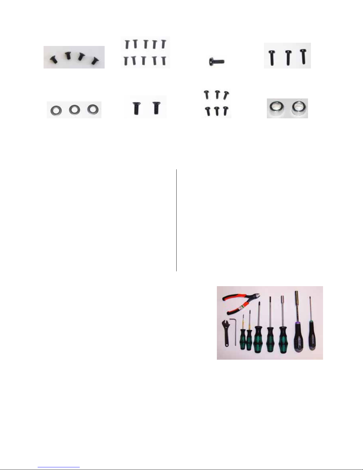
The MAC 575 Krypton Low-Noise Upgrade Kit contains the following items:
ABCD
EFGH
IJKL
MNOP
QRST
Table 1
Page 3
MAC 575 Krypton Low-Noise Upgrade Kit Installation Guide – Page 3 of 46
Tools required
Screw sizes given in this guide are indicative only.
The following tools are normally required to upgrade a
standard MAC 575 Krypton as described in this guide.
However, if screws have been replaced during service, for
example, you may find that other tools are require d .
• wire cutters
• adjustable wrench
• 4 mm Allen key
• 2 x flathead screwdrivers
• Pozidriv PZ1 and PZ2 screwdrivers (all cross-head screws in MAC 575 Krypton fixtures are Pozidriv,
not plain Phillips type)
• 10 mm and 8 mm hex head screwdrivers
• Torx TX10 and TX20 screwdrivers
• Round (needle) file
• Gaffa tape
• Spirit marker pen
To help you avoid dropping screws into the fixture, we recommend that you magnetize tools. Use of a
powered screwdriver with correctly set torque will also save you time.
UVWX
Y Z AA AB
Table 1
A Wiring harness P/N 11850227
B Wiring harness P/N 11850228
C SMPS to DC/DC PCB leads P/N 11850230
D High-voltage wiring diagram P/N 33120093
E Base shell with fans P/N 62408570
F SMPS bracket P/N 62408580
G Ballast mounting bracket P/N 62408370
H Ballast moun ting plate P/N 62408440
I Ballast mounting plate, terminals side P/N 62408400
J Inrush PCB P/N 62408390
plus P/N 62000144
K Vented panel for ballast-side
base side cover P/N 23912582
L Pan stop with switch P/N 62400815
M Grounding label for ballast P/N 33160051
N Ballast labe l P/N 33160050
O Voltaflex insulation for base side cover P/N 33001113
P V oltaflex insulation for pan frame P/N 33001114
Q Flexible cable retainer P/N 13101010
R M6x70 hex ballast mounting bolts x3 P/N 08111007
S M6 lockwasher P/N 08114401
T M3 lockwasher P/N 08054401
U M3x6 countersunk Torx screw x4 P/N 08050802
V M4x12 countersunk Torx screw x10 P/N 08070808
W M3x8 panhead Torx screw P/N 08050703
X M4x16 panhead Torx self-tap screw x3 P/N 08070703
Y M6 washer, stainless steel x3 P/N 08114302
Z M3x8 countersunk Torx screw x2 P/N 08050803
AA M4x10 phd. Torx tap + spike screw x6 P/N 08070701
AB Spacer Ø7/Ø4 x2 P/N 08261020
Parts list
Page 4
MAC 575 Krypton Low-Noise Upgrade Kit Installation Guide – Page 4 of 46
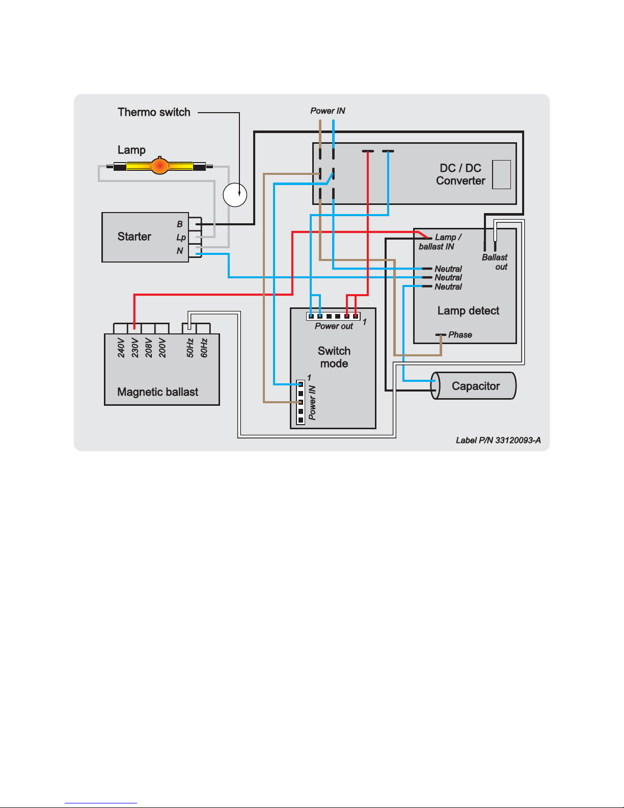
Schematic wiring diagram
Page 5
MAC 575 Krypton Low-Noise Upgrade Kit Installation Guide – Page 5 of 46
Replacement of components
To install the MAC 575 Krypton Low-Noise Upgrade Kit components in a standard MAC 575 Krypton
fixture:
1. Disconnect the fixture from
power, allow to co ol, and place
on a workbench. Take
precautions against ESD
(electro-static discharge).
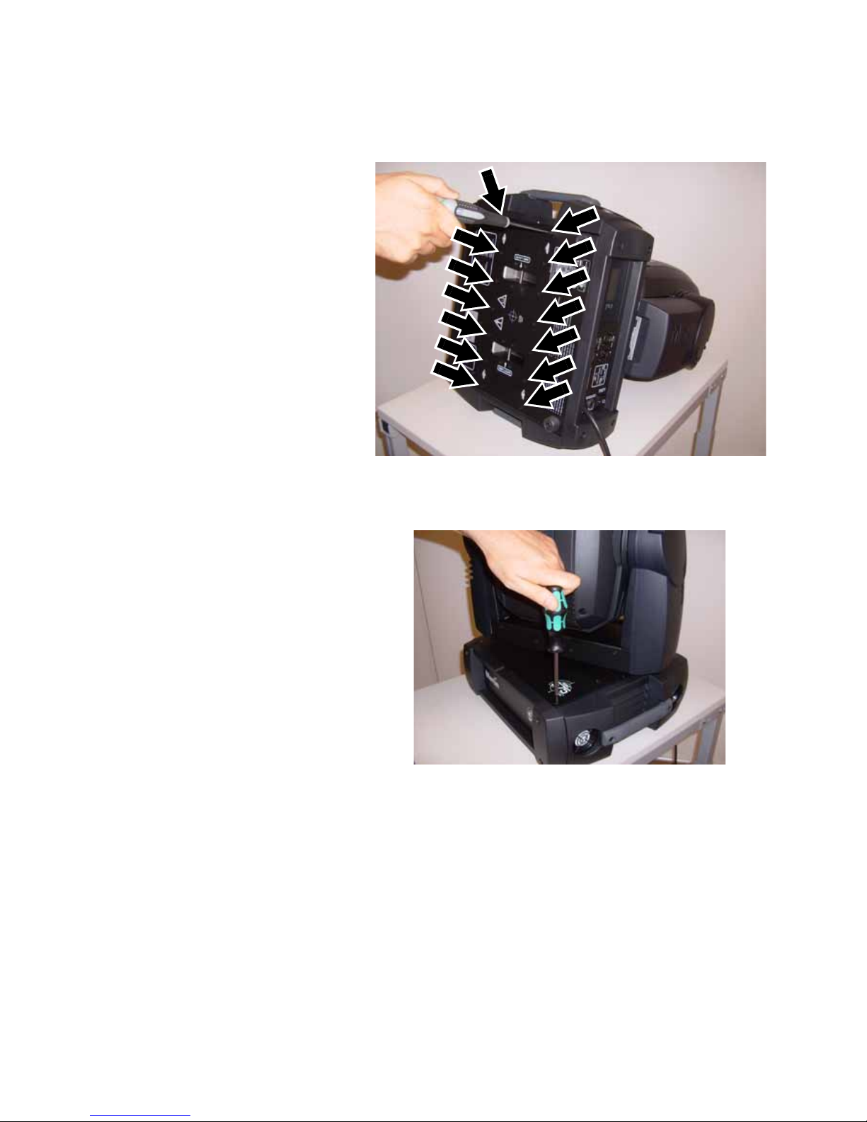
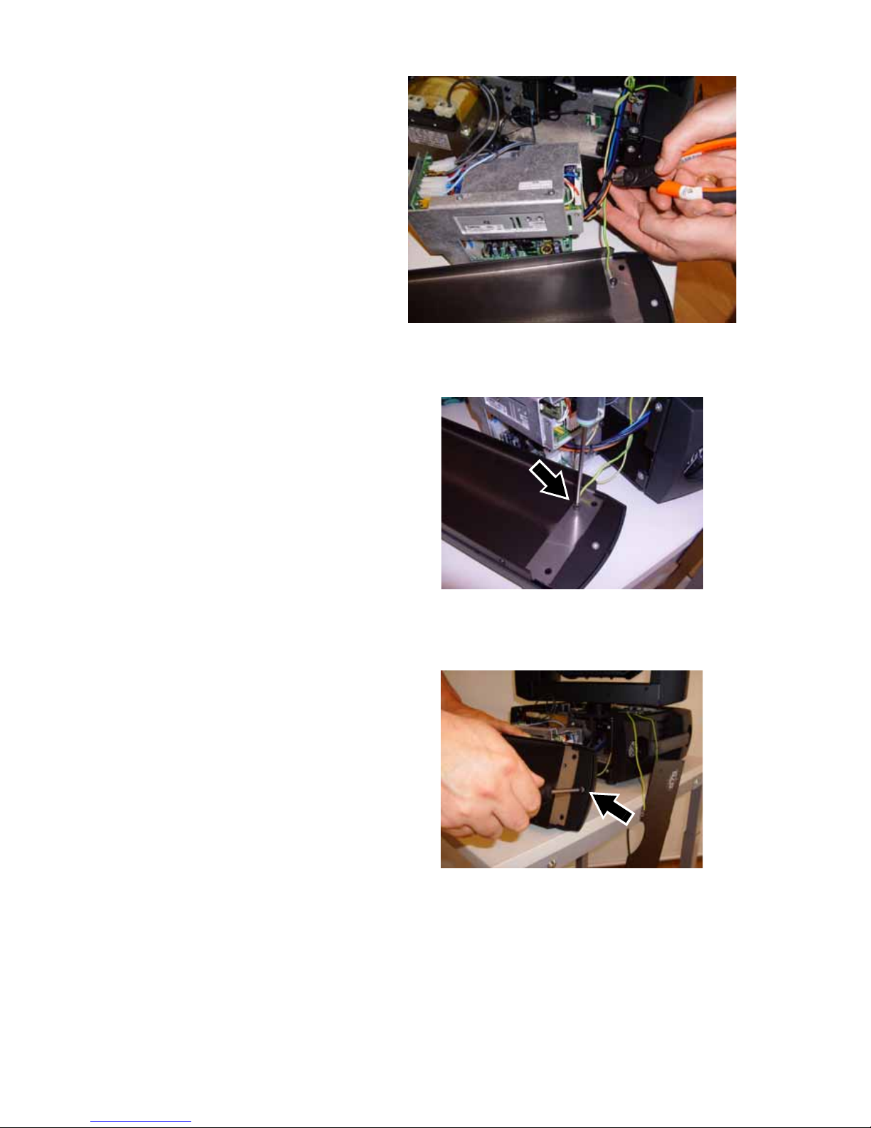
2. See Figure 1. Lay the fixture
on its side and remove the 14
Torx 20 pan frame retaining
screws (arrowed),
P/N 08070808, from the base.
Keep the screws for re-use.
3. See Figure 2. St and the fixture
upright. Remove the three PZ2
screws from the corners of
each base top cover (6 screws
total P/N 08070502) but do not
remove the ground (earth)
lead Torx screws that are set
slightly in from the corners of
the base covers. Keep screws
for re-use during reassembly.
Figure 1
Figure 2
Page 6
MAC 575 Krypton Low-Noise Upgrade Kit Installation Guide – Page 6 of 46
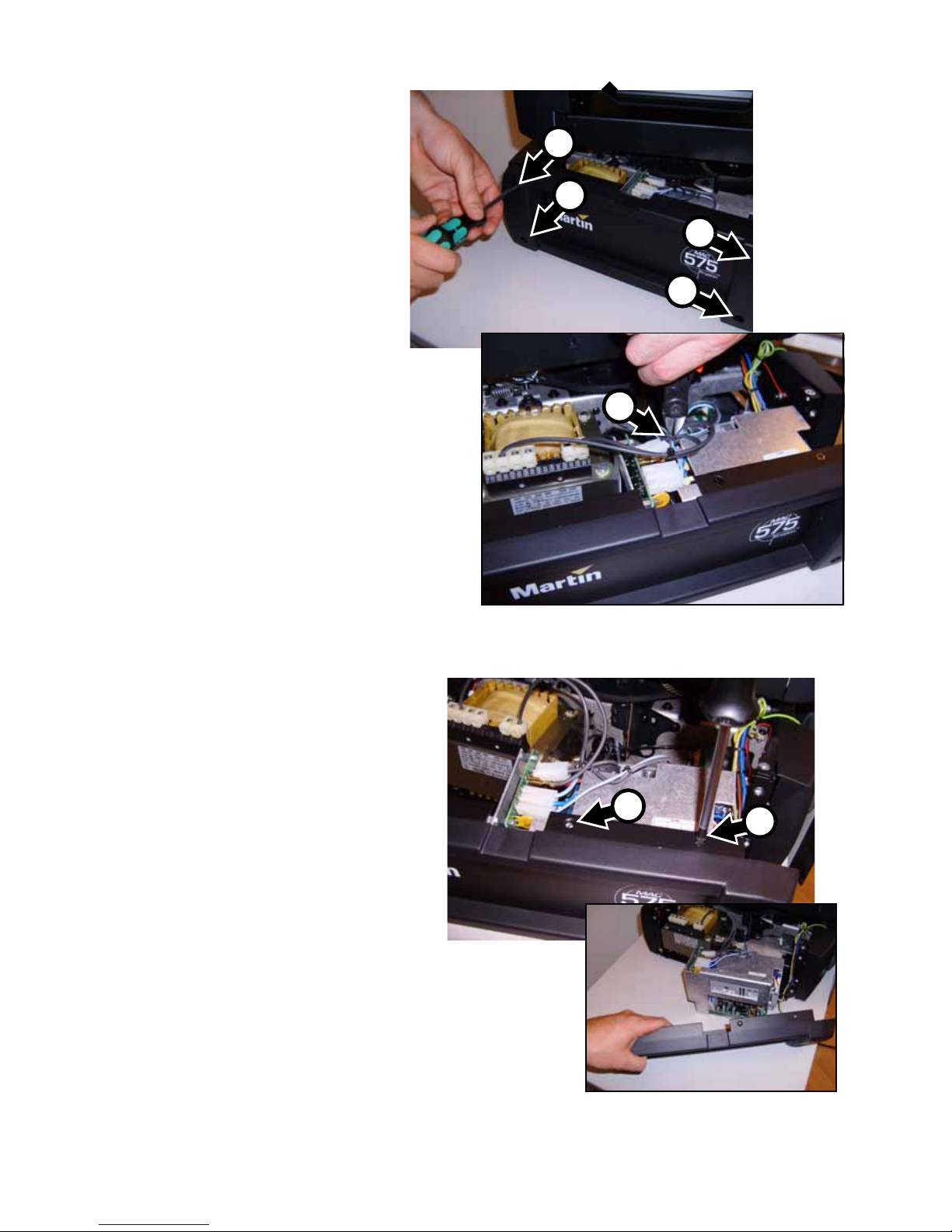
4. See Figure 3. Remove the four
PZ2 screws A from the base
side cover on the ballast side.
Keep the screws for re-use.
Cut cable ties B as necessary
to release the wiring to the
SMPS module and move the
cover away from the base.
5. See Figure 4. Remove the two
PZ2 screws C from the top of
the base side cover and lift the
cover away from the SMPS
module. The screws are no
longer required.
Figure 3
A
A
A
A
B
Figure 4
C
C
Figure 4
Page 7
MAC 575 Krypton Low-Noise Upgrade Kit Installation Guide – Page 7 of 46
6. See Figure 5. Cut cable ties as
necessary to release the base
side cover’s ground lead.
7. See Figure 6. Remove the
Torx 20 ground lead screw
(arrowed) from the base side
cover and disconnect the
ground lead. Keep the screw,
washer and ground lead for
re-use.
8. See Figure 7. Remove the
two PZ2 screws at each side
of the base cover and
remove the cover inner
panel. Keep the screws for
re-use. The cover inner panel
is no longer required.
Figure 5
Figure 6
Figure 7
Page 8
MAC 575 Krypton Low-Noise Upgrade Kit Installation Guide – Page 8 of 46
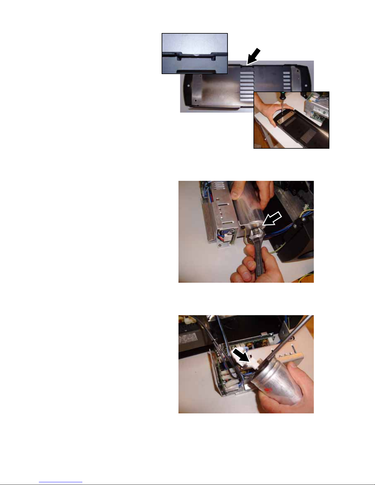
9. See Figure 8. A new inner
panel with air vents,
P/N 23912582, is supplied in
the Upgrade Kit. Turn the
inner panel so that the tab
(arrowed) in one edge of the
inner panel is lined up with
the channel in the base side
side cover. Use the two
screws you have just
removed to fasten the new
inner panel into the base side
cover. You are screwing into
plastic, so do not overtighten.
Put the side cover and inner
panel assembly to one side.
10. See Figure 9. Remove the
nut and lock washer from the
phase compensation
capacitor. Keep the nut and
washer for re-use.
11. See Figure 10. Disconnect
the spade connectors from
the phase compensation
capacitor and remove the
capacitor . Keep the capacitor
for re-use.
Figure 8
Figure 9
Figure 10
Page 9
MAC 575 Krypton Low-Noise Upgrade Kit Installation Guide – Page 9 of 46
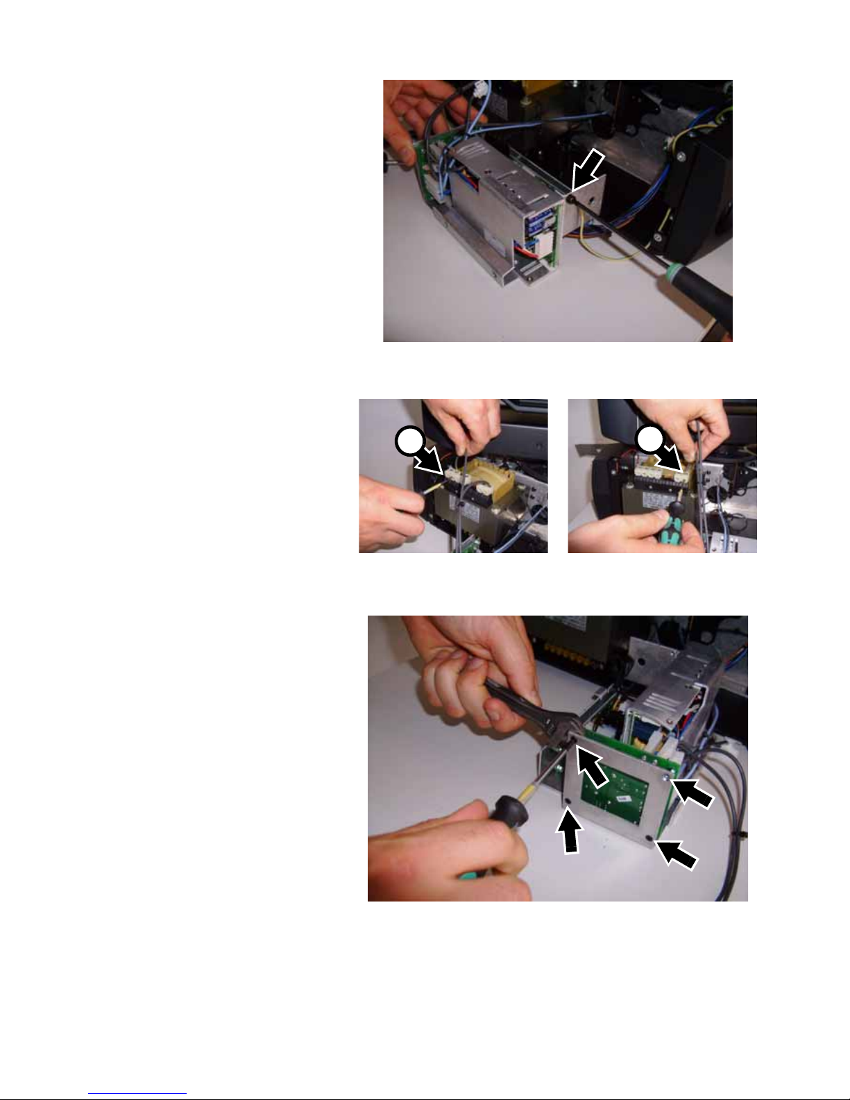
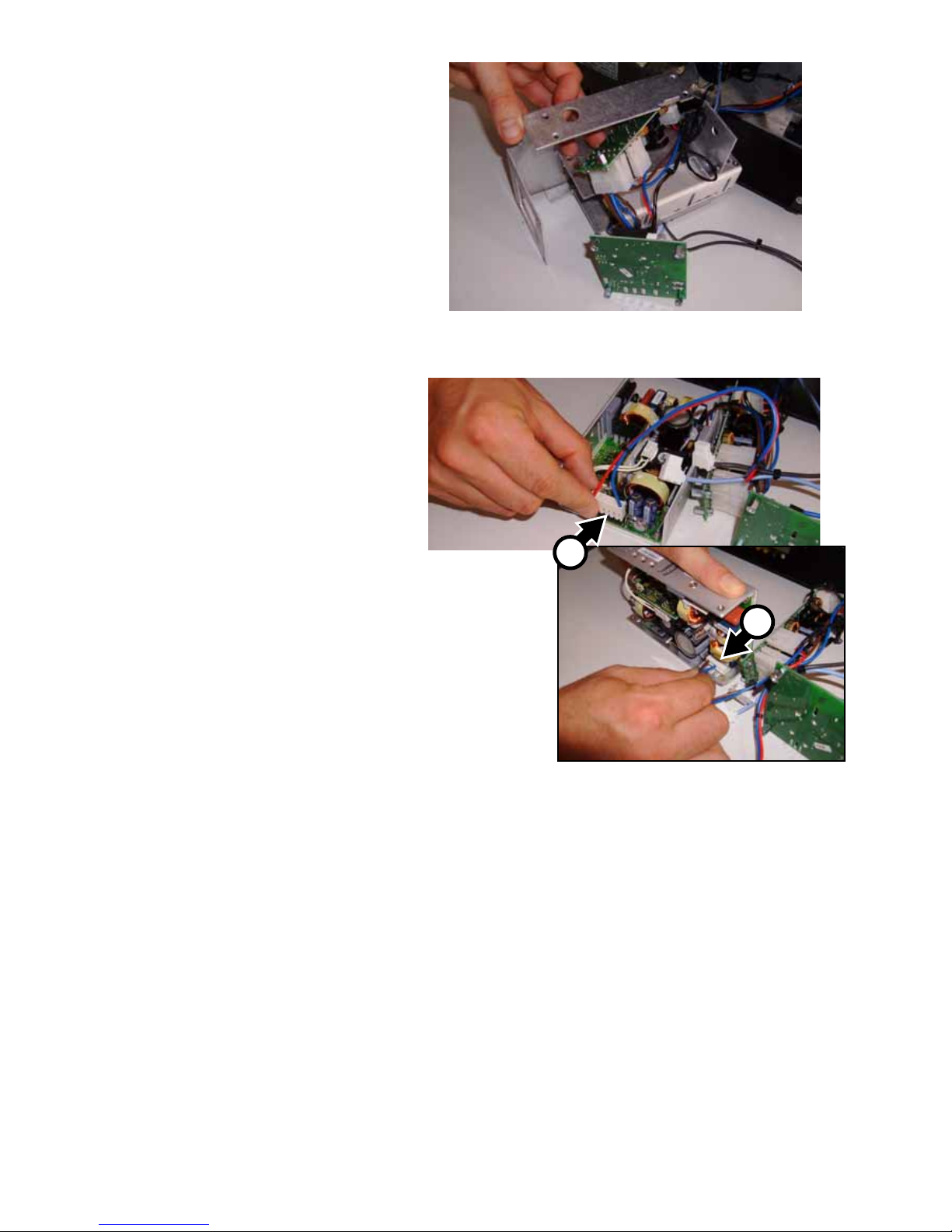
12. See Figure 11. Remove the
Torx 20 ground lead screw
(arrowed) from the end of the
SMPS (switch-mode power
supply). The screw, washer
and ground lead are no
longer required.
13. See Figure 12. Note which
terminals the voltage A and
frequency B tap leads on the
ballast are connected to and
use a small flathead
screwdriver to release the
tap leads from the terminals.
14. See Figure 13. Remove the
four Torx 10 screws from the
inrush PCB mounting posts,
using a wrench to hold the
mounting posts while you
loosen the screws. The
screws are no longer
required.
Figure 11
Figure 12
A
B
Figure 13
Page 10
MAC 575 Krypton Low-Noise Upgrade Kit Installation Guide – Page 10 of 46
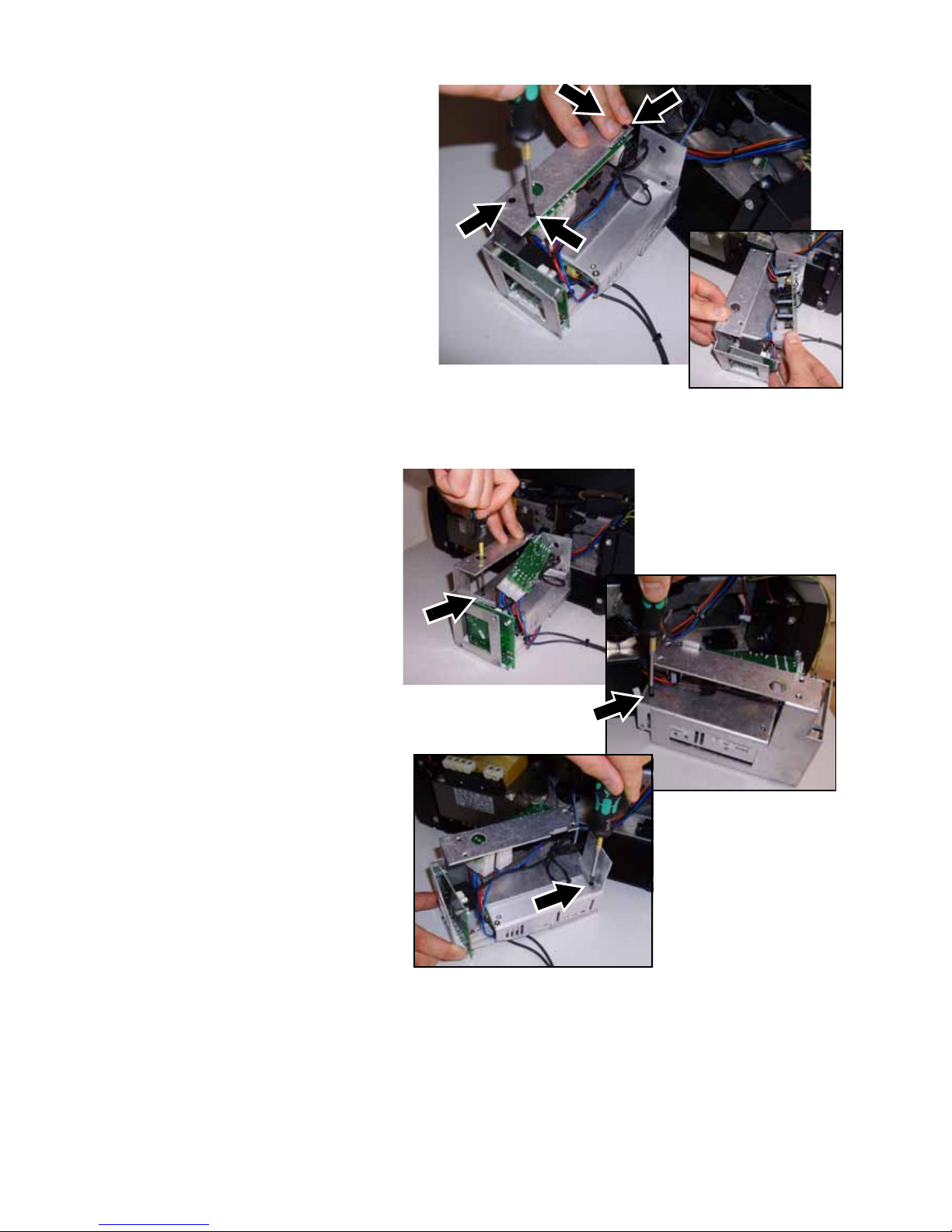
15. See Figure 14. Remove the
four Torx 10 screws
(arrowed, one screw is
hidden behind the
technician’s hand in the
photo) from the DC/DC PCB
mounting posts. These
screws are no longer
required. Move the DC/DC
PCB to one side for access
to the SMPS mounting
screws.
16. See Figure 15. Remove the
three Torx 10 SMPS
mounting screws (arrowed)
from the SMPS bracket.
Keep the screws for re-use.
Figure 14
Figure 15
Page 11
MAC 575 Krypton Low-Noise Upgrade Kit Installation Guide – Page 11 of 46
17. See Figure 16. Lift the SMPS
unit and the two PCBs out of
the bracket. The bracket is
no longer required, but keep
the other components.
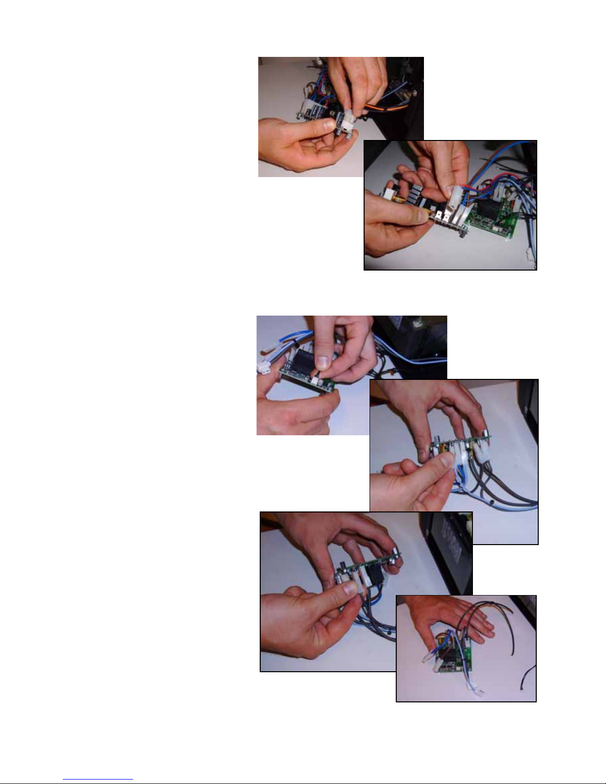
18. See Figure 17. Disconnect
the plug A with red and blue
leads from connector J2 and
plug B with blue and brown
leads from connector J1 on
the SMPS unit. Keep the
SMPS unit for re-use.
Figure 16
Figure 17
A
B
Page 12
MAC 575 Krypton Low-Noise Upgrade Kit Installation Guide – Page 12 of 46
19. See Figure 18. Disconnect all
connectors from the DC/DC
PCB. The red/blue leads and
the brown/blue leads are no
longer required. Remove the
DC/DC PCB and keep it for
re-use.
20. See Figure 19. Disconnect
the data wiring connector
from connector PL1 and the
light-blue and black starter
(ignitor) leads shown in
Figure 19 from the inrush
PCB. Remove the inrush
PCB, leaving the remaining
leads connected to it. The
PCB and these remaining
leads (shown at bottom right
in Figure 19) are no longer
required.
Figure 18
Figure 19
Page 13
MAC 575 Krypton Low-Noise Upgrade Kit Installation Guide – Page 13 of 46
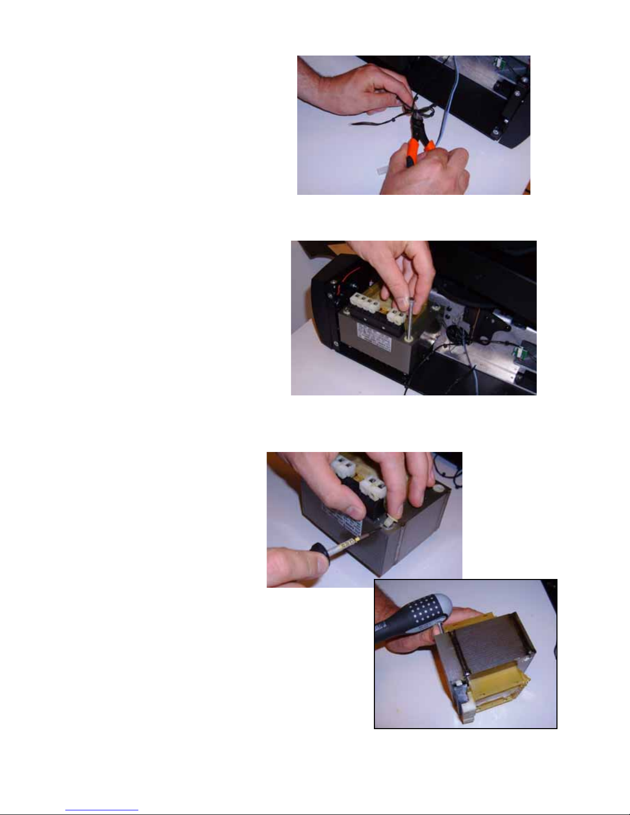
21. See Figure 20. Cut the cable
ties on the wiring to the data
connector you have just
removed from the inrush
PCB and pull the wiring free.
22. See Figure 21. Using an 8
mm socket driver, remo ve the
three M5 ballast mounting
bolts and lift the ballast out o f
the chassis. The bolts are no
longer required.
23. See Figure 22. Use a small
flathead screwdriver to lever
the plastic inserts out of the
ballast mounting bolt holes
on the top and the bottom of
the ballast. The inserts are
no longer required.
Important!The inserts are top-hat shaped,
with a sleeve inside the
mounting bolt hole and a collar
around the hole. If you break
off a collar, leaving the sleeve
stuck inside the hole, remove
the sleeve by knocking it out
with a bolt pushed through the
hole from the other side. Check
that all sleeves are removed
and holes are clear before
proceeding.
Figure 20
Figure 21
Figure 22
Page 14
MAC 575 Krypton Low-Noise Upgrade Kit Installation Guide – Page 14 of 46
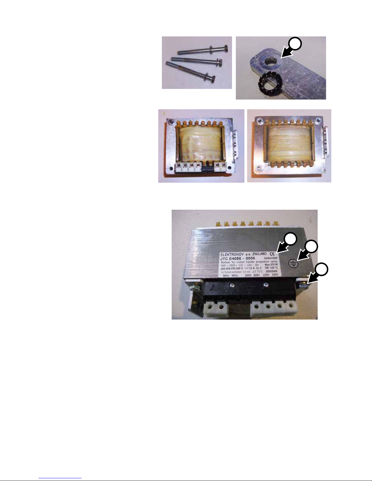
24. See Figure 23. Two new
ballast mounting plates, P/N
62408400 and P/N 62408440
an M6 star washer, P/N
08114401, three new M6
ballast mounting bolts, P/N
08111007 and three flat
washers, P/N 08114302, are
supplied in the Upgrade Kit.
On one plate there is a
countersunk recess. the star
washer must be installed
between the plate and ballast
here to ensure good electrical
continuity . Use a metal scraper
or sandpaper to clean the
surface of the ballast where
the star washer will sit. Use a
10 mm socket to install the
plates on the ballast as shown
in Figure 23 using the three
bolts supplied, with the star
washer sitting in its recess and
using flat washers under the
bolt heads.
25. See Figure 24. A label is stuck
on the side of the ballast next
to the terminals. Replace it
with the Elektrokov label C
supplied in the Upgrade Kit.
Apply the grounding label B
supplied in the Upgrade Kit
beside the Elektrokov label as
illustrated. This label indicates
that the ballast is grounded via
the bolt A and star washer.
Important!To maintain electrical continu ity,
the star washer must be
reinstalled in the same position
during future service operations.
Figure 23
A
Figure 24
C
B
A
Page 15

MAC 575 Krypton Low-Noise Upgrade Kit Installation Guide – Page 15 of 46
26. See Figure 25. Use a 7 mm
socket to remove the nuts
(arrowed) from the four screws
that hold the ballast mounting
brackets to the bottom of the
base. You will need to hold the
PZ2 screws in the base while
you loosen the bolts. Be
prepared to catch lockwashers
to avoid them falling inside the
fixture. One screw is hidden
under a label carrying patent
information. You will need to
scrape part of the label away
to free the screw . The bracket s
and their screws and bolts are
no longer required.
27. Remove the four PZ2 retaining
screws from the display side
base cover and lift the cover
away from the fixture slightly.
Keep the screws for re-use.
Figure 25
Figure 26
Page 16

MAC 575 Krypton Low-Noise Upgrade Kit Installation Guide – Page 16 of 46
28. See Figure 27. Disconnect the
display side base fan from the
top of the main PCB.
29. See Figure 28. Disconnect the
mains power leads (in a
braided sleeve) from the mains
filter PCB.
30. See Figure 29. Disconnect the
wiring to the DC/DC PCB from
its connector (arrowed) on the
bottom of the main PCB.
Figure 27
Figure 28
Figure 29
Page 17

MAC 575 Krypton Low-Noise Upgrade Kit Installation Guide – Page 17 of 46
31. See Figure 30. The wiring
harness that includes the main
PCB-to-DC/DC PCB leads
should now be free. Remove it.
This wiring harness is no
longer required.
32. See Figure 31. Disconnect the
SMPS side base fan at its
cable connector behind where
the SMPS is installed.
33. See Figure 32. Disconnect the
ballast side base fan at its
cable connector behind where
the ballast is installed.
Figure 30
Figure 31
Figure 32
Page 18

MAC 575 Krypton Low-Noise Upgrade Kit Installation Guide – Page 18 of 46
34. See Figure 33. Remove this
screw from the shield plate on
top of the pan frame. This
screw is no longer required.
35. See Figure 34. Remove this
screw and the cable retainer
mounted on it from the top of
the pan frame. This screw and
the cable retainer are no
longer required.
36. See Figure 35. Remove this
screw from the top of the pan
frame. This screw is no longer
required.
Figure 33
Figure 34
Figure 35
Page 19

MAC 575 Krypton Low-Noise Upgrade Kit Installation Guide – Page 19 of 46
37. See Figure 36. Remove this
screw from the top of the pan
frame. This screw is no longer
required.
38. See Figure 37. Remove the
two screws that hold the
ground leads on the top of the
pan frame at both sides and lift
the base top covers away from
the fixture. Keep the screws
and covers for re-use.
Figure 36
Figure 37
Page 20

MAC 575 Krypton Low-Noise Upgrade Kit Installation Guide – Page 20 of 46
Warning! To reduce the risk of injury to yourself or damage to the fixture, two people are required for the
next operation.
39. See Figure 38. While one
person lifts the head and yoke
assembly out of the fixture, the
other person must slide the
base out from underneath,
leaving the
display/connections panel and
main PCB connected to the
head and yoke. Do not discard
the base yet.
40. See Figure 39. Lay the head
and yoke assembly on its side.
Pull the light-blue and black
starter leads A and data leads
B in through the circular cutout
in the pan frame, pass them
back out through the
rectangular cutout C, pull to
remove any slack in the leads,
then tape them out of the way
D against the side of the pan
frame.
41. See Figure 40. Pull the head
and yoke wiring harness out of
the pan frame, removing any
slack, and secure the harness
with an elastic band (see
arrow).
Figure 38
Figure 39
A
B
D
C
Figure 40
Page 21

MAC 575 Krypton Low-Noise Upgrade Kit Installation Guide – Page 21 of 46
42. After you have pulled wiring
out of the pan frame to remove
slack, the pan frame should
look as shown in Figure 41.
Check that all wiring is secured
and that there is no slack
wiring in the pan frame. Make
absolutely certain that no
wiring can hang under the
motors (arrowed).
Important!When the pan frame is installed,
there is not much clearance for
wiring and there is almost no
clearance between the motors
(arrowed) and the base. Any
wiring that becomes trapped
under the motors or other parts
of the pan frame during
installation of the head and yoke
can be damaged, either during
installation or when the head is
panned after reassembly.
43. See Figure 42. Remove the
Allen screws from the handles
and remove the handles from
the base. Keep the handles
and screws for re-use. The
base is no longer required.
44. See Figure 43. Put the new
base on your workbench
beside the head and yoke
assembly. Turn the base so
that the side of the base that
has two fans is on the same
side as the rectangular cutouts
in the pan frame, as shown in
Figure 43. Tape the fan leads
(arrowed) in the new base out
towards the outside of the
base to keep them out of the
way.
Figure 41
Figure 42
Figure 43
Page 22

MAC 575 Krypton Low-Noise Upgrade Kit Installation Guide – Page 22 of 46
45. See Figure 41. Lower the head
and yoke assembly carefully
into the center of the new base
so that the pan frame fits over
the rigging clamp anchoring
points (arrowed) and the screw
holes at the edges of the pan
frame line up with the screw
holes in the sides of the new
base. Do not trap any wires.
46. See Figure 45. Eight screws
for the pan frame are supplied
in the Upgrade Kit: six M4x10
Torx 20 panhead self-tapping
screws, P/N 08070701, and
two M4x16 Torx 20 panhead
self-tapping screws, P/N
08070703. Two spacers,
P/N 08261020, are also
supplied. Remove the existing
screw at
a. Install the two
spacers on the two M4x16
screws and tighten them in the
holes at
a and b next to the
pan tacho wheel shield (see
photo A). Remove the existing
screw at
c. Tighten two of the
six M4x10 screws in the holes
at
c and d. Remove the
existing screw at
e. Tighten
two more of the six M4x10
screws in the holes at
e and f.
Remove the existing screw at
g. Tighten the last two M4x10
screws in the holes at
g and h.
Figure 44
Figure 45
A B
C D
a
b
d
c
e
f
h
g
Page 23

MAC 575 Krypton Low-Noise Upgrade Kit Installation Guide – Page 23 of 46
47. See Figure 46. Feed the
head/yoke wiring harness back
into the pan frame. Turn the
head to full pan left and full pan
right, checking that wiring is
free to move without chafing
and that the head pans freely.
48. Connect the three ground
leads from the head/yoke,
power input and display side
base top cover as shown in
Figure 47, re-using the original
screw.
49. See Figure 48. Take the new
wiring harness, P/N 11850227
supplied in the upgrade kit
(see “B” on page 2) and plug
the connector with the blue
and brown mains power leads
(arrowed) into the power leads
with the braided sleeve on the
main PCB.
Figure 46
Figure 47
Figure 48
Page 24

MAC 575 Krypton Low-Noise Upgrade Kit Installation Guide – Page 24 of 46
50. See Figure 49. Plug the 8-pin
multi-connector on the new
wiring harness into the
connector (arrowed) on the
bottom of the main PCB as
illustrated.
51. See Figure 50. Pass the blue
and brown power lead and
remaining multi-connector on
the new wiring harness
through the pan frame and into
the ballast side of the base.
Figure 49
Figure 50
Page 25

MAC 575 Krypton Low-Noise Upgrade Kit Installation Guide – Page 25 of 46
52. See Figure 51. Untap e the
leads from the fan closest to
the display panel and plug
them into connector F3
(arrowed) between connectors
F2 and F4 on the main PCB.
53. See Figure 52. Making sure no
wiring is trapped, re-install the
display/connections panel,
re-using the original four PZ2
screws, then re-install the base
top cover on the
display/connections side of the
fixture re-using the original
three screws.
Figure 51
Figure 52
Page 26

MAC 575 Krypton Low-Noise Upgrade Kit Installation Guide – Page 26 of 46
54. See Figure 53. On the ballast
side of the base, remove the
tape you used to secure the
light-blue and black starter
leads and data leads and pass
them out through the side of
the pan frame between the two
fans in the base.
55. See Figure 54. If pan switch
P/N 62400544 is fitted, it must
be removed and replaced with
pan switch P/N 62400815
supplied in the Upgrade Kit. If
pan switch P/N 62400815 is
already fitted, leave it in place.
Figure 53
Figure 54
P/N 62400815 P/N 62400544
if fitted, remove and
replace with P/N 62400815
Page 27

MAC 575 Krypton Low-Noise Upgrade Kit Installation Guide – Page 27 of 46
56. If you do not need to replace
the pan switch, go to step 61.
on page 28.
If you need to replace the pan
switch, See Figure 55.
Remove the two Torx 20
mounting screws (arrowed)
from the existing pan switch.
Keep the screws for re-use.
57. See Figure 56. Transfer the
spade connectors from the old
pan switch to the new switch.
Bend the spades downwards
in the direction of the arrow.
58. See Figure 57. Insert a
mounting screw in the switch’s
round hole and screw it in until
it is finger-tight only.
Figure 55
Figure 56
Figure 57
Page 28

MAC 575 Krypton Low-Noise Upgrade Kit Installation Guide – Page 28 of 46
59. See Figure 58. Insert the
second mounting screw in the
elongated hole and.screw in
until it is finger-tight only.
60. See Figure 56. Adjust the
position of the pan switch until
there is approx. 2 mm
clearance between the switch
activation blade A and the
toothed pulley B but make sure
that the blade can still be
activated by the pan stop tab C
when you rotate the yoke to full
pan. Fasten the switch in place
by fully tightening its two
mounting screws, starting with
the screw in the elongated
hole. After tightening the
screws, check the position of
the switch and readjust if
necessary.
61. See Figure 60. Cut the cable
tie (arrowed) holding the
ballast side fan leads to the
pan frame.
Figure 58
Figure 59
B
A
C
Figure 60
Page 29

MAC 575 Krypton Low-Noise Upgrade Kit Installation Guide – Page 29 of 46
62. See Figure 61. Remove the
two Torx 10 screws (arrowed)
from the thermosensor and let
the thermosensor hang on its
leads. The screws are no
longer required.
63. See Figure 62. The
thermosensor leads are
fastened with cable ties to the
SMPS side fan leads. They
must be fastened to the ballast
side fan leads instead. Be
careful not to mix up the SMPS
side and ballast side fan leads,
as they are about the same
length and look the same.
Carefully cut the cable ties that
hold the thermosensor leads to
the SMPS side fan leads.
Figure 61
Figure 62
Page 30

MAC 575 Krypton Low-Noise Upgrade Kit Installation Guide – Page 30 of 46
64. See Figure 63. Attach the
thermosensor leads to the
ballast side fan leads, leaving
approx. 10 cm (4 inches) extra
length on the thermoswitch
wires. Use two cable ties next
to each other to reduce the
strain on the leads.
65. See Figure 64. Remove two
Torx 20 screws (arrowed) from
the ballast side of the pan
frame next to the pan switch.
These screws are no longer
required.
Figure 63
Figure 64
Page 31

MAC 575 Krypton Low-Noise Upgrade Kit Installation Guide – Page 31 of 46
66. See Figure 65. A new ballast
mounting bracket, P/N
62408370, is supplied in the
Upgrade Kit. Take the
thermosensor you unfastened
in step 62. and clip it onto the
mounting pillars in the SMPS
bracket. You may need to
enlarge the holes in the
thermosensor PCB slightly
with a round file.
67. Install a cable tie on the
bracket as shown in Figure 66.
68. Three new M4x16 Torx 20
self-tapping screws, P/N
08070703, are supplied in the
Upgrade Kit. Fasten the
mounting bracket to the pan
frame as shown in Figure 67,
tightening the new screws in
the holes indicated with
arrows.
Figure 65
Figure 66
Figure 67
Page 32

MAC 575 Krypton Low-Noise Upgrade Kit Installation Guide – Page 32 of 46
69. See Figure 68. Thread the
thermosensor leads and
ballast side fan leads that you
attached in step 64. through
the opening (arrowed) in the
ballast mounting bracket.
70. See Figure 69. Reconnect the
thermosensor leads to the
thermosensor.
71. See Figure 70. Remove the
tape from the ballast side fan
leads and connect the fan.
Figure 68
Figure 69
Figure 70
Page 33

MAC 575 Krypton Low-Noise Upgrade Kit Installation Guide – Page 33 of 46
72. See Figure 71. Secure the
ballast side fan leads and
thermosensor leads to the
ballast mounting bracket with
the cable tie (arrowed) you
installed in step 67. Make sure
that leads are held securely
away from the fan blades.
73. See Figure 72. Remove the
tape from the SMPS side fan
leads and connect them to the
original connector.
74. See Figure 73. Use two cable
ties to take up the slack in the
SMPS side fan leads.
Figure 71
Figure 72
Figure 73
Page 34

MAC 575 Krypton Low-Noise Upgrade Kit Installation Guide – Page 34 of 46
75. See Figure 74. Six M4x12 Torx
20 screws, P/N 08070808, are
supplied in the Upgrade Kit.
Lay the fixture on its side and
fasten the ballast into its
bracket by tightening these six
screws through the holes
(arrowed) in the bottom of the
base, through the ballast
mounting bracket and into the
ballast mounting plates.
76. See Figure 75. Re-use 12 of
the 14 Torx 20 screws you
removed in step 2. to fasten
the pan frame/yoke/head
assembly into the base by
tightening the screws in the
holes (arrowed) in the bottom
of the base.
77. See Figure 76. Use a 5.5 mm
socket to remove the mounting
pillar nuts from the DC/DC
PCB. The nuts are no longer
required.
Figure 74
Figure 75
Figure 76
Page 35

MAC 575 Krypton Low-Noise Upgrade Kit Installation Guide – Page 35 of 46
78. See Figure 77. A new SMPS
mounting bracket, P/N
62408380, is supplied in the
Upgrade Kit. Press the DC/DC
PCB onto the mounting pillars
on this bracket.
79. Two new sets of leads, both
included under P/N 11850230,
for the SMPS are supplied in
the Upgrade Kit. Plug them
into the connectors on the
SMPS as shown in Figure 78.
Figure 77
Figure 78
Page 36

MAC 575 Krypton Low-Noise Upgrade Kit Installation Guide – Page 36 of 46
80. See Figure 79. Fasten the
SMPS mounting bracket onto
the SMPS using the two M3x8
countersunk Torx 10 screws,
P/N 08050803, supplied in the
Upgrade Kit. Install the cable
retainer, P/N 13101010,
supplied in the Upgrade Kit at
A.
81. See Figure 80. Fasten the new
ground lead supplied in the
Upgrade Kit onto the SMPS
mounting bracket with the
M3x8 panhead Torx 20 screw,
P/N 08050703, supplied in the
Upgrade Kit, installing the star
washer, P/N 08054401,
supplied in the Upgrade Kit
under the head of the screw.
Figure 79
A
A
Figure 80
Page 37

MAC 575 Krypton Low-Noise Upgrade Kit Installation Guide – Page 37 of 46
82. See Figure 81. Use a star
washer and nut to fasten the
phase correction capacitor
onto the SMPS bracket.
83. Peel off the backing paper
from the bigger of the two
pieces of “Voltaflex” insulating
sheet, P/N 33001 113, supplied
in the Upgrade Kit and stick it
over the center of the inner
surface of the base side cover
on the ballast side of the base.
84. See Figure 83. Re-using the
Torx 20 screw you removed in
step 7., attach the ground lead
for the ballast side panel and
the new ground lead that you
fastened to the SMPS bracket
in step 81. together on the
ballast side base cover inner
panel.
Figure 81
Figure 82
Figure 83
Page 38

MAC 575 Krypton Low-Noise Upgrade Kit Installation Guide – Page 38 of 46
85. See Figure 84. Fasten the
SMPS assembly to the flap on
the ballast side cover using
four new M3x6 countersunk
Torx 10 screws, P/N
08050802, supplied in the
Upgrade Kit.
86. See Figure 85. Connect the
double red lead from the 6-pin
connector on the SMPS to the
spade connector at PL 101 A
on the DC/DC PCB.
Connect the double blue lead
from the 6-pin connector on
the SMPS to the spade
connector at PL 102 B on the
DC/DC PCB.
Figure 84
Figure 85
B A
Page 39

MAC 575 Krypton Low-Noise Upgrade Kit Installation Guide – Page 39 of 46
87. See Figure 86. Connect the
brown lead from the 5-pin
connector on the SMPS to the
spade C at PL 108 on the
DC/DC PCB.
Connect the blue lead from the
5-pin connector on the SMPS
to the spade D at PL 105 on
the DC/DC PCB
88. See Figure 87. Connect the
brown lead from the wiring
harness you installed in step
49. to the spade at PL 109 on
the DC/DC PCB.
Connect the blue lead from the
wiring harness you installed in
step 49. to the spade at
PL 106 on the DC/DC PCB
89. The DC/DC PCB should now
look as shown in Figure 88.
Figure 86
C
D
Figure 87
Figure 88
Page 40

MAC 575 Krypton Low-Noise Upgrade Kit Installation Guide – Page 40 of 46
90. See Figure 89. Plug the 8-pin
multi-connector on the wiring
harness to the 8-pin socket
(arrowed) on the DC/DC PCB.
91. See Figure 90. Take the
wireset included in P/N
1 1850228 supplied in the
Upgrade Kit. Connect the blue
lead’s connector A to the
spade at PL 104 and connect
the brown lead’s connector B
to the spade at PL 107 on the
DC/DC PCB.
Figure 89
Figure 90
B
A
C
D
E
Page 41

MAC 575 Krypton Low-Noise Upgrade Kit Installation Guide – Page 41 of 46
92. See Figure 91. Connect the
blue and black right-angled
spade connectors C in Figure
90 to the spades on the phase
compensation capacitor
(arrowed). Polarity is not
important, but the right-angled
connectors must face away
from each other as shown in
Figure 91.
93. See Figure 92. Using a small
flathead screwdriver, fasten
the bare white lead D in Figure
90 in the frequency terminal on
the ballast that matches your
local mains power AC
frequency.
Figure 91
Figure 92
Page 42

MAC 575 Krypton Low-Noise Upgrade Kit Installation Guide – Page 42 of 46
94. See Figure 93. Using a small
flathead screwdriver, fasten
the bare red lead E in Figure
90 in the voltage terminal on
the ballast that matches your
local mains power voltage.
95. See Figure 94. Bend the
cable retainer clip on the
SMPS assembly so that it
holds wires securely away
from the ballast and holds
the part of the wireset that
has the braided sleeve so
that it is kept below the pan
switch assembly.
Warning! Make sure that no wiring will
come into contact with any part
of the ballast apart from the
terminals.
96. Reinstall the ballast side
base cover on the base,
re-using the screws you
removed in step 4.
97. See Figure 95. Stick the
narrow strip of “Voltaflex”
self-adhesive insulating sheet
supplied in the Upgrade Kit
over the inner surface of the
pan frame (arrowed), where
the wiring harness exits the
pan frame between the two
fans in the side of the base.
Figure 93
Figure 94
Figure 95
Page 43

MAC 575 Krypton Low-Noise Upgrade Kit Installation Guide – Page 43 of 46
98. See Figure 96. Take the
ground leads from the vented
side panel and the base top
cover on the ballast side of the
base and fasten them to the
top of the pan frame re-using
the screw you removed in step
38.
99. A wiring diagram label, P/N
33120093, is supplied in the
Upgrade Kit. Peel off the
backing paper and stick it to
the inside of the ballast side
top cover.
100.Make sure that wiring is
secured away from moving
parts and cannot be trapped,
then reinstall the base top
cover on the ballast side of the
base, re-using the original
three screws.
101.See Figure 98. Take the new
inrush PCB module supplied in
the Upgrade Kit and connect
the data leads (arrowed).
Figure 96
Figure 97
Figure 98
Page 44

MAC 575 Krypton Low-Noise Upgrade Kit Installation Guide – Page 44 of 46
102.See Figure 99. Install the
black starter lead on the
spade A at PL8.
Install the blue (Neutral)
starter lead on the middle
spade B in the row of three
spade connectors marked
NEUTRAL.
Install the white lead on the
spade C marked BALLAST
OUT next to the black
connector at PL8.
Connect the red and black
double spade connector to
the spade D marked
LAMP/BALLAST IN at PL3.
Connect the brown lead to
the spade E marked PHASE
at PL2.
Connect the remaining two
blue leads to the two
remaining connectors
marked NEUTRAL on either
side of spade B. It does not
matter which of these two
leads you connect to which
spade.
103.See Figure 100. After
making all connections to the
inrush PCB assembly, it should
now look like this. Use the four
new M4x12 Torx screws, P/N
08070808, supplied in the
Upgrade Kit to fasten the
inrush PCB assembly to the
base between the two fans.
Important!Do not trap any wiring when
installing the inrush current PCB
assembly.
Figure 99
B
A
B
C
E
D
Figure 100
Page 45

MAC 575 Krypton Low-Noise Upgrade Kit Installation Guide – Page 45 of 46
104.See Figure 101. Re-using the
original screws, install the
base outer side covers and
carrying handles.
You have now completed the
installation of components, but do
not begin using the fixture until you
have carried out the safety tests
described in the next section.
Safety testing
Warning! The two tests described below must be carried out before the upgraded MAC 575 Krypton
Low-Noise can be considered safe. Do not operate the fixture until it has passed these tests.
Specialized test equipment is required for these two tests. Suit able test equipment, such as the Electrical
Safety Tester series from Instek (http://www.instek.com) for example, is available at the moment
(summer 2008) for around 600-700 US dollars.
Ground bond test (earth bond test)
105.Open the ballast side base top cover. Test the resistance between the ground (earth) conductor in
the power cable and each of the ground leads on the pan frame in turn. If resistance exceeds 0.75
ohms, clean and re-establish all connections and repeat the test until you measure less than 0.75
ohms between the ground conductor in the power cable and each of the two gro und leads. Do not
proceed to the next test until the fixture passes this test.
106.Reinstall the cover.
High-potential dielectric withstand test
Warning! Dangerous voltage. Follow all safety instructions printed in your appliance tester’s user manual
and on your appliance tester.
107.Ensure that the fixture’s power cable is not connected to power. Temporarily lin k the live (brown) and
neutral (blue) conductors in the fixture’s power cable together so that there is electrical continuity
between them.
108.Connect one terminal of a PAT (portable appliance tester) device to the combined live and neutral
conductors in the fixture’s power cable. Connect the other terminal of the PAT device to the ground
conductor in the fixture’s power cable.
109.Make sure that the fixture’s main on/off power switch is set to ON.
110.You are about to apply a very dangerous and potentially lethal voltage. Ensure that it is impossible
for exposed conductive components in or on the fixture to come into contact with persons, or any
conductive surface or substance that persons may touch, during this test.
1 11. Set the maximum current on your PAT device to 20 mA, then use the PAT device to apply 1500 VAC
for a maximum of 1 second to the conductors you have connected it to.
Figure 101
Page 46

MAC 575 Krypton Low-Noise Upgrade Kit Installation Guide – Page 46 of 46
112.If a flashover or arcing occurs, disconnect the PAT device, check all points of the installation, then
repeat the test.
113.Separate the live and neutral conductors again before connecting the fixture to normal AC power.
Product information
For specifications and other information about the MAC 575 Krypton, please refer to the user manual
originally supplied with the fixture. The manual is also available for download from the Support area of
the Martin website at http://www.martin.com.
Martin Professional A/S • Olof Palmes Allé 18 • 8200 Aarhus N • Denmark
Tel: +45 8740 0000 • Fax +45 8740 0010 • www.martin.com
 Loading...