

Page 1
MAC 500/E
user manual
Page 2

© 1997 - 2000 Martin Professional A/S, Denmark.
All rights reserved. No part of this manual may be
reproduced, in any form or by any means, without
permission in writing from Martin Professional A/S,
Denmark.
Printed in Denmark.
P/N 35000016, Rev. E
Page 3

section 1
Introduction
MAC 500/E safety information....................................................................................................................................................4
section 2
Setup
Unpacking....................................................................................................................................................................................5
Installing or changing the lamp....................................................................................................................................................5
Powering the fixture............................ .... ............................................... .......................... ................................ .......................... ..6
Rigging.................................. .... ......................... ............................................... ................................. ......................... .................6
Connecting the serial link ............................................................................................................................................................7
section 3
Operation
Martin RS-485 control.................................................................................................................................................................9
DMX-512 control.........................................................................................................................................................................9
Controllable effects....................................................................................................................................................................10
section 4
Control Panel
Menu navigation........................................................................................................................................................................12
Personality settings....................................................................................................................................................................13
Address and protocol selection..................................................................................................................................................14
Readouts.....................................................................................................................................................................................14
Manual control...........................................................................................................................................................................15
Stand-alone sequences ...............................................................................................................................................................15
Utilities....................................................................................................................................................................................... 16
section 5
Gobos and Color Filters
Gobo specifications.................................................................................................................................................................... 17
Gobo orientation and positions..................................................................................................................................................17
Changing rotating gobos......................... ......................... .......................... ......................... .......................... ... ..........................19
Changing static gobos......................... .... .... ... .......................... ......................... ............................................... .... .... ..................19
Default color filter positions......................................................................................................................................................20
Changing color filters............ ......................... .......................... ......................... ............................................ ... .... .... ... .... ...........20
section 6
Maintenance and Basic Service
Accessing parts ..........................................................................................................................................................................21
Removing the printed circuit board............................................ ................................................ ................................ ...............21
Replacing fuses..........................................................................................................................................................................22
Changing the XLR pin-out.........................................................................................................................................................22
Changing voltage and frequency settings..................................................................................................................................22
Updating software......................................................................................................................................................................23
Changing lenses................................................. ............................................... ................................ .........................................24
Replacing the lamp.....................................................................................................................................................................24
Optimizing lamp alignment................................................. .......................... ..................................................... .......................25
Installing the optional head shell safety wire.............................................................................................................................25
Maintenance schedule................................................................................................................................................................25
Cleaning.....................................................................................................................................................................................26
Lubrication.................................................................................................................................................................................26
section 7
Appendices
DMX protocol............................................................................................................................................................................27
Messages....................................................................................................................................................................................31
Troubleshooting ............................................................................................................... ......................................................... 32
Circuit board layout ................................ .... ......................... .......................... ..................................................................... .......33
Specifications.................... .... ......................... .......................... ......................... ............................................... ..........................34
3
Page 4

section 1
INTRODUCTION
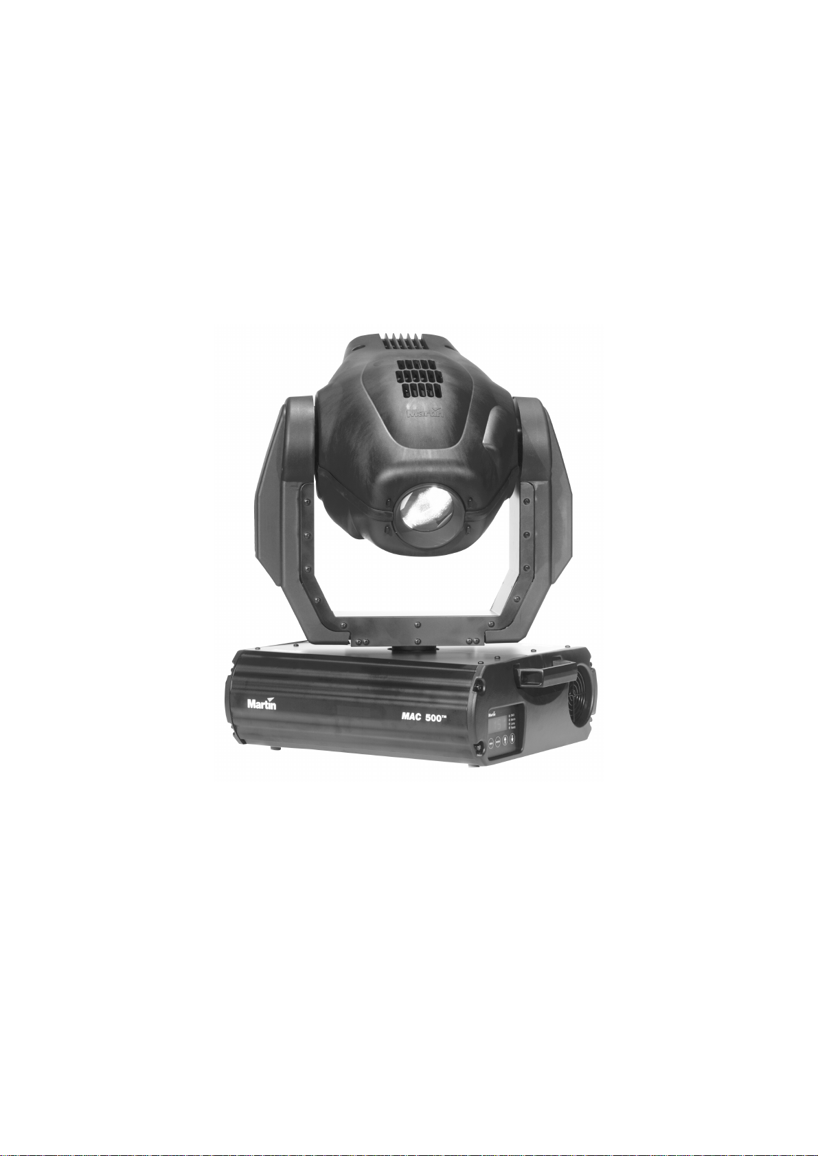
Thank you for purchasing the MAC 500/E moving-head spotlight from Martin. Every detail of its construction and
programming is de signed to make the MAC 500/Eextremelybright, quiet and reliable. With proper setup and maintenance, it will provide years of trouble-free operation.
This manual covers the MAC 500 with magnetic ballast and the MAC 500 E with electronic ballast. “MAC 500/E”
refers to both models wh en describing common features and proced ures. The features in software version 1.9 ar e
described. The latest MAC 500/E news and software is available from the Martin web site at http://www.martin.dk.
MAC 500/E safety information
This product is for professional use only. It is not for household use.
This product presents risks of lethal or severe injury due to fire and heat, electric shock, ultraviolet radiation, lamp
explosion, and fal ls. 5HD G WKLVP DQXD O before powering or installing the fixture, follow the safety precautions listed
below and observe all warnings in this manual and printed on the fixture. If you have questions about how to operate
the fixture safely, please contact your Martin dealer or call the Martin 24-hour service hotline at +45 70 200 201.
WARNING!
To protect yourself and others from electric shock
• Disconnect the fixture from AC power before removing or installing the lamp, fuses, or any p art, and when n ot in use.
• Always ground (earth) the fixture electrically.
• Use only a source of AC power that complies with local building and electr ical cod es and has both overlo ad and
ground-fault protection.
• Do not expose the fixture to rain or moisture.
• Refer any service operation not described in this manual to a qualified technician.
To protect yourself and others from UV radiation and lamp explosion
• Never operate the fixture with missing or damaged lenses and/or covers.
• When replacing the lamp, allow the fixtur e to c ool for at le ast 15 minut es bef ore op ening th e fix ture or remo ving
the lamp. Protect your hands and eyes with gloves and safety glasses.
• Do not stare directly into the light. Never look at an exposed lamp while it is lit.
• Replace the lamp before usage exceeds the maximum service life, or i f th e lamp is defective or worn out.
To protect yourself and others from burns and fire
• Never attempt to bypass the thermostatic switch or fuses. Always replace defective fuses with ones of the specified type and rating.
• Keep all combustible materials (for example fabric, wood, paper) at least 1.0 meter (39 inches) away from the
fixture. Keep flammable materials well away from the fixture.
• Do not illuminate surfaces within 1.0 meter (39 inches) of the fixture.
• Provide a minimum clearance of 0.1 meters (4 inches) around fans and air vents.
• Never place filters or other materials over the lens.
• The exterior of the fixture can reach temperatures up to 140° C (284° F). Allow the fixture to cool for at least 5
minutes before handling.
• Do not modify the fixture or install other than genuine Martin parts.
• Do not operate the fixture if the ambient tem perature (Ta) exceeds 40° C (104° F).
To protect yourself and others from injury due to falls
• When suspen ding the f ixtur e ab ove ground leve l, ver if y that th e stru ct ure ca n hol d a t leas t 10 tim es th e weigh t of
all installed devices.
• Verify that all external covers and rigging hardware are securely fastened and use an approved means of secondary attachment such as a safety cable.
• Block access below the work area whenever installing or removing the fixture.
• Do not lift the fixture by its head.
4
MAC 500/E User Manual
Page 5
section 2
SETUP
This section describes the steps required to prepare the MAC 500/E for operation.
Unpacking
The MAC 500/Epackage includes:
• 2 Fast-Lock clamp brackets
• 5-meter XLR-XLR control cable
• User manual
• 7 extra gobos
• 1 spare rotating gobo spring
The packing material is carefully designed to protect the fixture during shipment - always use it or a custom MAC 500/
600 flight case to transport the fixture.
1RWH0$&IOLJKWFDVHVSURGXFHGEHIRUH6HSWHPEHUDUHQRWGHHSHQRXJKIRUWKH0$&( These flight
cases can be identified by the outside measurements: 860 mm (34") from bottom to top, including wheels, on the outside. Suitable flight cases measure 894 mm (35.2") from bottom to top, including wheels.
Installing or changing the lamp
WARNING!
Disconnect the fi xture from A C power before p roceeding. Always wea r safety
goggles to protect your eyes and allow a hot lamp to cool for at least
15 minutes before removing it from the fixture.
The MAC 500/E is designed to work with the Philips MSR-575/2, Philips MSD-575, Osram HSD-575, or the Osram
HSR-575/2 dis c harge lamps. ,QVWDOOLQJDQ\RWKHUODPSPD\GDPDJHWKHIL[WXUHThe lamp holder is pre-adjusted at the
factory; precise alignment may be necessary due to slight variations between lamps. The procedure is described on
page 25.
1. The MAC 500/E must be cool and isolated from AC power. Remove the 2 screws holding the lamp
assembly. Gently remove the assembly.
2. If changing the lamp, remove the old lamp from the socket.
3. Holding the new lamp by its ceramic base (do not touch the glass), carefully insert it firmly and
squarely into the lamp socket.
4. Clean the glass bulb with the cloth supplied with the lamp, particularly if your fingers touch the
glass. A clean, lint-free cloth wetted with alcohol may also be used.
5. Re-insert the lamp assembly and replace the screws.
Setup
5
Page 6

6. Before turning the lamp on, reset the RLAH and RLST counters. See “Readouts” on page 14.
Powering the fixture
For protection from dangerous electric shock, the fixture must be grounded
(earthed). The AC mains supply shall be fitted with a fuse or circuit breaker
Check voltage and frequency settings
7KHYROWDJHDQGIUHTXHQF\VHWWLQJVPXVWPDWFKWKHORFDO$&SRZHUVXSSO\ Operating at the incorrect setting ca n resu lt
in poor light ou tput, shorte ned lam p lif e, overhe atin g and damage to the fixt ure. The settin gs are p rinted o n th e serial
number label on t he bo tt om of th e ba se: i f th e v olt age does no t match t he lo cal su pp ly or the fr equ ency ( 5 0/ 60 Hz) i s
different, then the bal last and/or transf ormer must be rewired as described on page 22.
Install a plug on the power cord
You may need to install a cord cap that fits your supply on the power cable. Following the manufacturer’s instructions,
install an appro ved 3-pron g grounding -type plu g that fits your supply. Connect the wires to the pins as listed below.
The table shows some possible pi n identification schemes; if the pins are not clearly identified, or if you have any
doubts about proper installation, consult a qualified electrician.
WARNING!
and ground-fault protection.
Rigging
Wire Pin Marking Screw (US)
brown live “L” yellow or brass
blue neutral “N” silver
yellow/green ground green
When ready to operate, conn ect th e MAC 500 /E directly to AC power .'RQRWFRQQ HFWLW WR D GLPPHUV\VWHPGRLQJVR
PD\GDPDJHWKHIL[WXUH To apply power, set the power switch on the base to the “I” position.
WARNING!
Use 2 clamps to rig the fixture. Lock each clamp with both fasteners.
The 1/4-turn fasteners are locked only when turned fully clockwise.
Attach an approved safety cable to the base.
The MAC 500/E can be place d direct ly on t he stage flo or or ri gged in any orienta tio n on a trus s. The inte grated FastLock system enables quick and easy fastening of the clamp adapters in 4 different positions as shown below. See
page 35 for a list of suitable clamps available from Martin.
1. Verify that the rigging clamps (not included) are undamaged and can bear at least 10 times the weight
of the fixture. Bolt th e clamps securely to the clamp brackets with a grade 8.8 (minimum) M12 bolt and
lock nut, or as recommended by the clamp manufacturer.
2. Tip the MAC 500/E on its side or install the clamps while the fixture is in the flight case.
3. Align a clamp with 2 mounting points. Insert the fasteners into the base and turn both levers a
full 1/4-turn clockwise to lock. Install the second clamp.
4. Verify that the structure can bear at least 10 times the weight of all installed fixtures, clamps,
cables, auxiliary equipment, etc.
6
MAC 500/E User Manual
Page 7

5. Working from a stable platform, hang the fixture on the truss. The front of the fixture is indicated
safety wire
attachment point
arrow points to front
(neutral pan)
by the arrow on the base.
6. Install a safety wire that can bear at least 10 times the weight of the fixture. The attachment
point is designed to fit a caribiner clamp.
ment.
7. Tighten the rigging clamps securely to the structure.
8. Verify that there are no combustible materials or surfaces to be illuminated within 1 meter of the
fixture, and that there are no flammable materials nearby.
When rigging the fixture within 1 meter of other fixtures, avoid illuminating
one fixture with another. The intense light can melt plastic parts.
Connecting the serial link
Tips for building a serial link
1. Use shielded twisted-pair cable designed for RS-485 devices: standard microphone cable cannot
transmit DMX data reliably over long runs. For links up to 300 meters (1000 ft.) long, you can use 24
AWG, low capacitance, 85-150 ohm characteristic impedance, shielded cable with 1 or more twisted
pairs. For runs up to 500 meters (1640 ft.) use 22 AWG cable. Use an amplifier if the serial link
exceeds 500 meters.
2. Never use a “Y” connector to split the link. To split the serial link into branches use a splitter
such as the Martin 4-Channel Opto-Isolated RS-485 Splitter/Amplifier.
3. Do not overload the link. Up to 32 devices may be connected on a serial link.
4. Terminate the link by installing a termination plug in the output socket of the last fixture on the
link. The termination plug, which is simply a male XLR connector with a 120 ohm, 0.25 watt
resistor soldered between pins 2 and 3, “soaks up” the control signal so it does not reflect back
down the link and cause interference. If a splitter is used, terminate each branch of the link.
Never use the carrying handles for secondary attach-
IMPORTANT!
Connecting fixtures
The MAC 500/E has locking 3-pin data input and output sockets that can be configured for use with either DMX or
Martin Protocol controll e rs. 7KHGHIDXOWSLQRXWLVFRQILJXUHGWRWK H'0;VWDQGDUG, i.e., pin 1 to shield, pin 2
to signal (-) and pin 3 to signal (+).
3-pin to 3-pin
Phase-Reversing
Cable
Connections
Male Female
1
2
3
P/N 11820006
1
2
3
3-pin to 5-pin
Phase-Reversing
Cable
Connections
Male Female
1
2
3
P/N 11 820 00 2
1
2
3
4
5
5-pin to 3-pin
Phase-Reversing
Cable
Connections
Male Female
1
2
3
4
5
P/N 11 82 000 3
Setup
5-pin to 3-pin
Straight
Cable
Connections
Male Female
1
2
3
1
2
3
4
5
P/N 1 1820005
1
2
3
3-pin to 5-pin
Straight
Cable
Connections
Male Female
1
2
3
P/N 1 1820004
1
2
3
4
5
7
Page 8

1. Connect the controller’s data output to the MAC 500/E’s data input. For a
• DMX controller with 5-pin output: use a cable with 5-pin male and 3-pin female connectors such
as P/N 11820005. Pins 4 and 5 are not used.
• DMX controller with 3-pin output: use a cable with 3-pin male and fema le connec tors suc h as the
one supplied.
• Martin RS-485 Protocol controller: use a phase-reversing cable, such as P/N 11820006, with 3-
pin male and female connectors or reconfigure the XLR output.
2. Continue the link: connect the output of the fixture closest to the controller to the input of the
next fixture. Use a phase-reversing cable when connecting a DMX-standard (pin 3 +) device to a
Martin-standard (pin 3 -) device.
Ω
3. Insert a male 120
XLR termination plug in the output of the last fixture on the link.
8
MAC 500/E User Manual
Page 9

section 3
OPERATION
This section describes the MAC 500/E’s controllable ef fects and the option s for custom izing th em for yo ur appli cation .
Option selection is described in the next section.
Martin RS-485 control
The MAC 500/E may be controlled with the Martin 3032 controller with version 2.04 or later software. To respond to
the controller, either the p rotocol setting (
or automatic protocol detection (
dummy command and wait 1 second to allow the fixture to respond before sending real commands.
DMX-512 control
The MAC 500/E may be operated with USITT DMX512 controllers in 4 modes that combine tracking or tracking/vector movement with 8-bit or 16-bit pan/tilt resolution.
Tracking control
Tracking is available in all 4 DMX modes. With tracking control, the controller calculates the positions along the path
between an effect’s starting point and it’s ending point. It uses the fade tim e to calculate the change (delt a) of each
update or refresh, which the fixture “tracks.” For smooth movement with any fade time, the MAC 500/E has a filter
algorithm that looks at several position updates (samples), and calculates the ideal speed.
PSET) must be set to Martin (MART) as described in the previous section,
SPEC/AUTO) must be enabled. If automatic protocol detection is enab le d, se nd a
This algorithm is adjustable to compensate for controllers that calculate position changes unevenly. In most cases the
default settings work well.
If movement is not satisfactory there are 2 parame ters that can be ad justed. The first is the calculation method used and
is select ed un der
change in DMX; it is the best ch oice with controll ers that calcul ate inte rmediate po sitions tha t are clos e to the lin e of
travel. MO d2 uses the real value of the DMX delta to calculate speed and is better if the intermediate positions stray
significantly from the line of travel.
The second parameter is the number of position updates used to calculate speed. The level is adjustable between 1 and
10 under SPEC/TRAC/CA L. Increasing the number of samples increases the distance over which speed is calculated, making move ment smoother but less responsive to sudden changes.
The ideal settings for both parameters will vary from controller to controller: experiment for best results. The real
value algorithm (
SPEC/TRAC/MOdE. MOd1, the default, calculates speed based on the absolute value of the
MOd2) is recommended when using the MAC 500/E with the Martin Lighting Director system.
Vector control
With vector control, available in DMX modes 3 and 4, the fixture is given just 1 position - the end position - and a
speed, which is set on a separate channel. )RUVPRRWKPRYHPHQW WK H ID GH WLPH PXVWEHVHWWRLH WK HHIIHFW³EXPSV´
RU³VQDSV´IURPRQHSRVLWLRQWRWKHQH[W With controllers that do not have programmable fade times, vector control
provides a way to set speed. Because the end poin t and speed are kn own from the begin ning, vecto r control resu lts in
smooth movement regardless the fade time or the controller’s processing power.
The speed channels allow vector control to be turned off, resulting in tracking control. In addition, they offer a “blackout speed,” described bel ow, and overrides of the
cuts) personality settings.
PTSP (pan/tilt speed), MOdE (studio m ode ), and SC UT (short-
When blackout speed is enabled, effects move at full speed. The dimmer/shutter closes while the effects move to make
the transition invisible . Dimmer/shutter strobe and pulse effects, however, override the blackout command.
8-bit versus 16-bit pan/tilt resolution
With 8-bit pan/tilt resolution, the pan and tilt are divided into 256 equal increments. Finer position control and
smoother movement is provided in the 16-bit modes, which divide the full pan range into 32,768 increments and the
full tilt range into 45,567 increments.
Operation
9
Page 10

Controllable effects
All moving effects are reset to a “home” po sition when the fixture is powere d up. The fixture can also be res et via
DMX if DMX reset (
the MAC 500/E even if this feature is disabled; see the DMX protocol for details.
An on-the-fly position correction system monitors the position of the color wheels, fixed-gobo wheel, and rotating
gobos. If an error is detected, the shutter closes and the effect is reset to its home position. Normal operation resumes
immediately thereafter. This feature can be disabled by setting effects feedback (
General operation may be optimized for speed or quietness with the studio mode setting (SPEC/MOdE). The menu
setting may be overrid den via DMX using the effects speed channel in DMX modes 3 and 4.
Lamp
The MAC 500/E can be set to automatically strike the lamp within 90 seconds of being powered on by setting the
Automatic Lamp On (
lamps from striking at the same time.
If Automatic Lamp On is set to o ff (default), the lamp rem ains o ff until a “lamp on” c omman d is sent from th e con tro ller. A peak of electric current that can be many times th e operating current i s drawn for an instant when stri king the
lamp: striking man y lamps at once ma y cause a voltage dro p large enough to pre vent lamps from striking or tr ip the
main circuit breaker. Avoid this by programming a “l amp on” sequence that stri kes lamps one at a time at 5 secon d
intervals .
SPEC/dRES) is enabled. There is also a combination of DMX values that allows you to reset
SPEC/ALON) personality to ON. A delay determined by the fixture add ress prevents all
SPEC/EFFb) to OFF.
Power to the lamp can be turned off from the controller if the DMX Lamp Off (
There is also a combination of DMX values that allows you to turn off the lamp even if this feature is disabled; see the
DMX protocol. %H FDUHIXO: it is not possible to strike the lamp within 8 minutes of having switched it off. The MAC
500/E will store a “lamp on” command and strike the lamp automatically when the 8 minutes have elapsed.
With the MAC 500 E, lamp power falls to 400 watts for cooler operation and longer lamp life when the shutter is
closed for 10 seconds. Power instantly returns to full when the shutter opens. Reduced power mode can also be forced
- with the shutter open - by setting channel 1 to a DMX value from 73 to 79.
SPEC/dLOF) feature is enabled.
Pan and tilt
The moving head pans 440° and tilts 306°. Movement may be optimized for speed by setting the pan/tilt speed
(
PTSP) personality to FAST, or for smoothne ss by setting it to SLOW. The setting may be overridden on the speed
channel in vector mode. Setting the movement speed to “blackout” in vector mode causes the shutter to black out the
light while the mirror is moving. The pan and tilt channels (DMX) can be inverted and/or swapped for convenience
using the pan/tilt (
PATI) menu.
Color wheels
The MAC 500/E has 2 9-pos ition -pl us-o pen col or whe els, yi el ding a total o f 100 po ssibl e c ombina tions . The 4 temp erature correction filters and 14 d ichroic co lors combin e in 67 useful w ays that c an be c alled on 1 DMX channe l. Both
wheels can be scrolled, allowing for split color effects, snapped to fixed positions, and continuously rotated in both
directions at different speeds. The 67 colors can be called randomly on DMX ch annel 4.
The Shortc uts (
turn in one direction only. The setting may be overridden on the speed channel in vector mode. Setting the color speed
to “blackout” in vector mode causes the shutter to black out the light while the wheels are moving.
SPEC/SCUT) setting determines whether the wheels take the shortest path to the next position or
Focus
The beam may be focused from 2 meters (6.5 feet) to infinity. The beam angle with the standard lenses is 17°. An
optional 23.5° wide-angle len s set is available as well. See “Accessories” on page 35.
Fixed (static) gobos
There are 2 operat ing modes availabl e for the f ixed-g obo wheel, which has 9 positio ns for met al gobos plus an open
position. In “fixed” mode (
speeds. In “scroll” mode (
2 directions at variable speed.
Setting the fixed-gobo speed to “blackout” in vector mode causes the shutter to black out the light while the wheel
turns from one position to another.
SPEC/gMOd/FIX), the wheel steps between fixed posi tions and sha kes at variable
SPEC/gMOd/SCRL), the wheel scrolls continuously, shakes at 1 speed, and rotates in
10
MAC 500/E User Manual
Page 11

The Shortcu ts (SPEC/SCUT) setting determines whether the gobo wheel takes the shortest path to the next position or turns in one direction only. The setting may be overridden on the speed c hannel in vector mode.
Rotating gobos
The MAC 500/E has 5 rot ati ng po si tio ns fo r gl as s or me ta l g obos. Gobo s may be ro t ated i n both di rec tio ns at v ar yin g
speeds or indexed to any position. The function and gobo are selected on channel 5 and the velocity or index position
are selected on channel 6. Setting the rotating-gobo speed to “blackout” in vector mode causes the shutter to black out
the light while the wheel turns from one po sition to anothe r and, if indexi ng is selecte d, while the gobo rotates betwe en
positions.
To change the gobos, see “Gobo orientation and positions” on page 17.
Iris
The iris diameter ranges from 100 to 15 percent open. There are 6 variable/ran dom pulsating iris effects cal lable on
channel 9. These can be disabled by switching DMX Macros (
ting (
SPEC/IRR) closes the iris slightly from full open to eliminate a halo effect seen in very early units.
SPEC/dMAC) off. The iris reflection reduction set-
Rotating prism / variable frost
The 3-facet prism can rotate in both directions at varying speeds. There are 8 preprogrammed macros that combine the
prism with rotating gobos on channel 10. These can be di sabled by switching DMX Macros (
Setting the prism speed to “b lack ou t” in ve c to r mo de cau ses the shu tter to b lack out the ligh t whil e th e prism mov e s in
and out.
An optional frost filter may be installed in place of the rotating prism to provide a variable fro st ef fect. If th e frost f ilter
is installed, the fixture type persona lit y (
protocol.
SPEC / FTYP) must be set to “FROS” to enable the frost variation of the
SPEC/dMAC) off.
Dimmer / shutter
The mechanical dimmer/shutter system provides smooth, high-resolution 100 percent dimming, “instant” open and
blackout, random an d vari able strob e effects u p to 23 Hz , an d ra ndom and vari able pu lses in whic h th e d immer sna ps
open and slowly dims or sna ps closed and slowly opens. The pulse and rando m strobe effects can be disabled by
switching DMX Macros (
The Dimmer Mode (SPEC/dMOd) setting allows you to select between linear or simulated tungsten fade curves.
The fade time must be 0 to simulate tungsten dimming .
SPEC/dMAC) off.
Operation
11
Page 12
section 4
CONTROL PANEL
The 4-digit LED control panel on the front of the MAC 500/E allows you to set the address and personalities, read
lamp hours an d other informati on, cali brate effects, cont rol the fixture manually, and run stand-a lone test s and demo
programs. Most of these functions may be performed remotely via the serial link with the MPBB1 Uploader
The display can be flipped for easy reading by pressing the [↑] and [↓]keys simultaneously. The intensity is adjustable
and the display can be set to go out 2 minutes after the last key-press.
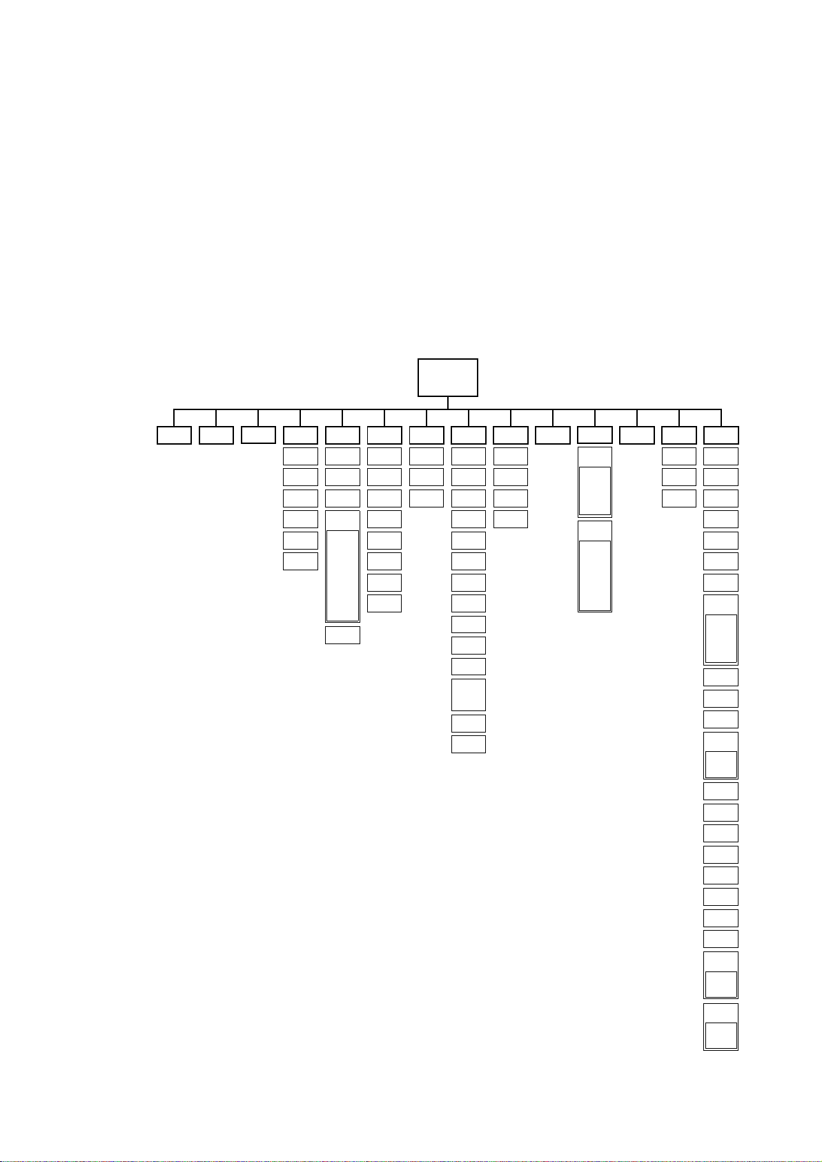
Menu navigation
The DMX or Martin address, depending on the protocol setting, and any error messages are displayed when the MAC
500/E is turned on. To enter the menu, press [MENU]. Use the [↑] and [↓]keys to move within the menu. To select a
function or submenu, press[ENTER]. To escape a function or menu, press [MENU].
Address/
Messages
PSET
dAdr
MAdr
TIME
Po H
RPoH
LA H
RLAH
LSTR
RLST
AdJ CAL PATI VER
RST
P OF
SWAP
L ON
LoFF
HEAd
dIM
COL1
COL2
Fgob
Rgob
FOCU
IRIS
PRIS
PATI
T OF
d OF
C1OF
C2OF
RGOF
FGOF
FOOF
PINV
TINV
MAN dMXL PTSP SPEC
RST
STCO
L ON
SHUT
LoFF
SHUT
dIM
COL1
COL2
Fgob
Rgob
FOCU
IRIS
PRIS/
FROS
PAN
TILT
TSEQ
....
E SP
dEMO
DEM1
PAN
TILT
FOCU
SEQ
DEM2
MINP
MAXP
MINT
MAXT
FOCU
SEQ
CPU
FEbA
dISP
FTYP
dISP
dINT
dLOF
dRES
ALON
FEbA
dFSE
FACT
CUS1
CUS2
CUS3
dFOF
AUTO
UPLd
TEMP
bASE
HEAd
PCbT
SCUT
IRR
FTST
dMAC
MOdE
dMOd
EFFb
TRAC
MOdE
CAL
gMOd
FIX
SCRL
12
MAC 500/E User Manual
Page 13

Personality settings
Personality Path Options Effect (Default settings shade d.)
Pan/tilt speed PTSP
Pan/tilt swap PATI/SWAP
Pan inverse PATI/PINV
Tilt inverse PATI/TINV
Fixture type SPEC/FTYP
Display on/off SPEC/dISP
Display in tensity SPEC/dINT
DMX lamp off SPEC/dLOF
DMX reset SPEC/dRES
Automatic lamp on SPEC/ALON
Automatic protocol
detection
Tracking algorithm SPEC/TRAC/MOdE
Tracking samples SPEC/TRAC/CAL
Shortcuts SPEC/SCUT
DMX macros SPEC/dMAC
Studio mode SPEC/MOdE
Fixed gobo mode SPEC/gMOd
Dimmer mode SPEC/dMOd
Pan/tilt feedback SPEC/FEbA
Effects feedback SPEC/EFFb
Iris reflection reduction
SPEC/AUTO
SPEC/IRR
FAST
SLOW
ON
OFF
ON
OFF
ON
OFF
PRIS
FROS
ON
OFF
10-10 0
ON
OFF
ON
OFF
ON
OFF
ON
OFF
MOd1
MOd2
1-10
ON
OFF
ON
OFF
NORM
STUd
FIX
SCRL
NORM
TUNG
ON
OFF
ON
OFF
ON
OFF
Optimize movement for speed*
Optimize movement for smoothness*
Map DMX pan control to tilt channel and vice versa
Normal pan and tilt control
Reverse DMX pan control, right Æ left
Normal pan control, left Æ right
Reverse DMX tilt control, down Æ up
Normal tilt control, up Æ down
Operate with rotating prism
Operate with optional variable frost
Display stays on
Display goes out 2 minutes after last key press
Adjust display intensity
Enable DMX lamp off command
Disable DMX lamp off command*
Enable DMX reset command
Disable DMX reset command*
Lamp strikes automatically within 90 seconds of power on
Strike lamp from controller
Enable automatic protocol detection
Disable automatic protocol detection
Absolute delta value algorithm (for most controllers)
Real delta value algorithm
Tracking mode sam ple leve l - defaul t is 6. H igher lev els give
smoother movement but slower acceleration.
Color wheels and fixed-gobo wheel turn the shortest
direction*
Wheels turn same direction*
Enable DMX-selectable macros and pulsating effects
Disable DMX-selectable macros and pulsating effects
Optimize effects for speed
Optimize effects for silence
Static gobo wheel steps between full positions
Static gobo wheel scrolls continuously
Normal dimming curve
Simulated tungsten dimming curve
Enable pan/tilt position correction system
Disable pan/tilt feedback. Setting not saved
Enable feedback from magnetic sensors on color
wheels, fixed-gobo wheel, and rotating-gobo index
Disable feedback from magnetic sensors
Iris opens 95 percent. Recommended for early units only
Iris opens 100 percent
* Setting may be overridden via DMX. See the protocol for details.
Control Panel
13
Page 14

Address and protocol selection
One of the operating modes shown below must be selected. Factors to consider when selecting a mode will depend on
your controller and are discussed in the previous section. Maximum flexibility is provided in mode 4.
Each fixture must be assigned its own channels to receive instructions from the controller. The address, also known as
the start channel, is the first channel used. Ad dresses are independent of the physical link: t hey may be set in any convenient order. Two MAC 500/Es may share the sa me address; however, they will receive the same instructions and
independent control will not be possible.
Mode Martin DMX 1 DMX 2 DMX 3 DMX 4
Movement speed Vector Tracking Tracking and/or Vector
Pan/tilt resolution 16 bit 8 bit 16 bit 8 bit 16 bit
Channels required 2 12 14 14 16
1. Apply power to the MAC 500/E.
2. If you want to change settings while the MAC 500/E is in a flight case, push [MENU] and
[ENTER] simultaneously to disable pan and tilt reset. The partial reset procedure can take 2 - 3
minutes and will result in error messages being displayed; this is not a fault with the fixture.
3. Press the [MENU] key and then press [↑] or [↓] until the display shows
4. Press [↑] or [↓] until the desired protocol (Martin, or DMX mode 1, 2, 3, or 4) appears on the dis-
play. Press [ENTER] to confirm.
5. Press [↑] or [↓] until the display shows
address). Press [ENTER] to confirm.
6. Press [↑] or [↓] to select the address. Press [ENTER] to confirm.
7. Press [MENU] to return to the main menu. The address is displayed.
PSET. Pre ss [ENTER].
dAdr (to set a DMX address) or MAdr (to set a Martin
Readouts
Usage readouts (TIME)
Read the total number of power-on hours (Po H), power-on hours since last reset (RPoH), total lamp hours (LA H),
lamp hours since last reset (
reset (
The resettable counters may be used to track overall usage and lamp life. To reset to zero, display the readout and then
press [↑] for 5 seconds.
DMX value readouts (dMXL)
Read the DMX start code (STCO) and DMX values received for each effect. This is an easy way to che ck that the
DMX start code is 0 and that the fixtu re is receiving the expected DMX values.
Software version readouts (VE R)
Read the version number of the CPU software (CPU), feedback circuit software (FeB A), and display module software (
Temperature readouts (SPEC/ TEMP)
Read temperature in the ba se (bASE) and head (HEAd) in Celsius. Temperatures below 25° C are shown as -25;
temperatures above 100° C are shown as
Thetemperature sensors are calibrated at the factory and adjustment should not be necessary. The following procedure
calibrates the sensors if they give no or faulty readings.
RLAH), total number of lamp strikes (LSTR), and the number of lamp strikes since last
RLST).
dISP). The CPU software version is also displayed for a moment at power up.
+100.
1. Allow the unit to cool to room temperature (powered off for at least 4 hours).
2. Measure the room temperature in Celsius. (To convert F° to C°, subtract 32° and then multiply
by 0.555.)
3. Power up the unit and allow it to reset.
14
MAC 500/E User Manual
Page 15

4. Press the [MENU] and [↓] keys at the same time and hold them for 3 seconds until “25” shows in
the display.
5. Press the [↑] and [↓] keys until the display shows the temperature measured.
6. Press [ENTER] to save the setting.
Manual control
Manual control (MAN)
The manual control menu permits you to do the following without a controller:
• reset the fixture (RST)
• turn the lamp on and off (
• open, close, and strobe the shutter at 3 speeds (
• control the dimmer (
• move the color wheels to each position and scroll them at 3 speeds (
• move the fixed-gobo wheel to ea c h positio n (
• move the rotating-gobo wheel to each position and rotate the gobos at 3 speeds (
• control the focus (
• control the iris (
• insert and rotate the prism (
• control pan and t il t (
Adjustment (AdJ)
L ON, LoFF)
SHUT)
dIM)
COL1, COL2)
Fgob)
Rgob)
FOCU)
IRIS)
PRIS) at 3 speeds, or, if a frost filter is installed, vary the frost (FROS)
PAN, TILT)
The adjustment menu provide s manual control for maki ng mechanical adjustme nts. These should be performed by a
qualified technician. The menu provides functions to reset the fixture (
LoFF), control all effects in the head (HEAd), and move the head to the home and extreme positions (PATI). The
HEAd submenu allows the technician to:
• open, close, and strobe the dimmer/shutter (
• move the color and gobo wheels through t heir positions (
• move the focus lens to its extreme positions (
• open and close the iris (
• insert and rotate the prism (
IRIS)
Stand-alone sequences
Demonstration programs (dEMO)
This menu offers 2 prep rogrammed demonstr ations. Dem o 1 shows each effect individ ually and in combina tion with
others at a set home position. Demo 2 pans and tilts within a defined area and shows various effect combinations.
Before running demo 1, set the pan/tilt position (
focus (
FOCU) the beam. Select SEQ to run the demo. Demo 2 is similar but instead of de fining a home po sition, you
define an area such as a screen or wall by setting the minimum and maximum pan and tilt positions (
MINT, MAXT). Focus the beam in the center of the area.
Test sequences
7HVWVHTXHQFHTSEQRun a general test of all effects.
RST), turn on and off the lamp (L ON,
dIM)
COL1, COL2, Fgob, Rgob)
FOCU)
PRIS)
PAN, TILT) to a good location for viewing the effects and then
MINP, M AXP,
3ULQWHGFLUFXLWERDUG WHVW
SPECPCBT This menu provides 4 tests of the circuit board for service use: TI,
T2, T3, and LEd.
)DFWRU\WHVWSPECFTST: This menu provides an effects test (ETST), a movement test (MTST), and a sensor
test (
STST) used for quality control. Th e sensor test includes programs for testing sensors on the color and gobo
wheels (
COL1, COL2, Rgo b, and Fgob).
Control Panel
15
Page 16

Utilities
Calibration (CAL)
The calibration menu allows you to adjust the effects to achieve total uniformity between fixtures: it is not a substitute
for mechanical adjustment. Select dimmer/shutter (
(
RGOF), fixed-gobo wheel (FGOF), or focus (FOOF) and adjust the effect’s offset with the arrow keys. Offsets are
adjustable from 1 to 255 for all effects except the fixed-gobo wheel, whic h is adjustable from 127 to 129. Press
[ENTER] to save the calibration.
d OF), color wheels (C1OF, C2OF), rotating-gobo wheel
Reset default offsets (SPEC/dFOF)
Reset all calibrations to their factory defaults. Select dFOF and press [ENTER] when SURE is displayed.
Reset default personality settings (SPEC/dFSE/ FACT)
Return all personality settings (not calibrations) to their factory defaults. Select FACT and press [ENTER] when
LOAD is displayed.
Custom configurations (SPEC/dFSE/CUS1, CUS2, CUS3)
Save and load 3 sets of c ustom configuration s. To save a custom configuration, adjus t the settings as desire d, go to
CUS1, CUS2, or CUS3 and press [ENTER] when SAVE is displayed. To load a custom setting, select it and
press [ENTER] when
LOAD is displayed.
Upload mode (UPLd)
Upload mode prepares the MAC 500/E to receive control software. It is normally engaged automatically when using
the MPBB1 or MP-2 uploaders In certain circumstances, however, you may have to set upload mode manually as
described under “Updating software” on page 23.
16
MAC 500/E User Manual
Page 17

section 5
GOBOS AND COLOR FILTERS
The MAC 500/E has 5 rotating positions for glass or metal gobos, 9 static positions for metal gobos, and 9 positions
for interchangeable dichroic glass color filters in special holders. This section describes how to replace these items.
Gobo specifications
For best results, MAC 500/E gobos should meet the following specifications.
Glass gobos
• Coating: ................................. ......................... .......................... ............. dichroic or enhanced aluminum
• Material: ........................................................................................high temperature, Borofloat or better
• Thickness:................................. ................................................ ... .... ... .................................. 1.1- 4.0 mm
• Outside diameter:........................................................................................................27.9 + 0 /- 0.3 mm
• Maximum image diameter:............................................................................................................23 mm
Glass gobos should be made wi th the ar twork rev ersed on the coa ted side. T his o rientati on give s the be st focus but is
not critical. We do not recommend using chrome-coated glass gobos in the MAC 500/E. They absorb more heat than
enhanced aluminum gobos and are likely to break or oxidize. If used, their lifetime can be extended somewhat by
inserting the gobos with the coated side towards the lamp.
Metal gobos
• Material: ...................................................................................................................................aluminum
• Thickness:................................................................................................................................... ..0.5 mm
• Outside diameter:........................................................................................................27.9 + 0 /- 0.3 mm
• Maximum image diameter:............................................................................................................23 mm
*Steel metal gobos may give acceptable short term performance. Gobos less than 0.5 mm thick may need to be secured
with a drop of high temperature silicone adhesive when used in the static positions.
Gobo orientation and positions
Glass gobos
1RWH*ODVVJRERVPD\EHXVHGLQWKHURWDWLQJJRERZKHHORQO\7KH\DUHWRRWKLFNIRUXVHLQWKHVWDWLFJRERZKHHO
For correct projection of text and images, the side with the true image must be installed facing in, towards the lamp.
For best focus, the co ated side of glass gobos sho uld face out, away from the lamp. Textured glass gobos must be
inserted with the smooth side facing in, towards the lamp.
When an object is held up to the uncoated side,
there is a space between the object and its reflec-
Coated Glass Gobos
tion. The edge can be seen through the uncoated
side.
Coated side towards stageUncoated side towards lamp
When an object is held up to the coated side, there
is no space between the object and its reflection.
The edge cannot be seen through the coated side.
Textured side towards stageSmooth side towards lamp
Textured Gobos
Gobos and Color Filters
17
Page 18

Metal and image gobos
Black side t
R
lFi
l
The metal gobos supplied with the MAC 500/E may be us ed in either wheel. They are bl ack on one side to reduce
reflections; the black side must face out, away from the lamp. For correct projection of text and images, the side with
the true image must be installed facing in, towards the lamp.
Reflective side towards lamp
Metal Gobos
Correct image towards lamp Reversed image towards stage
Image Gobos
Default gobo layout
otating-gobo whee
owards stage
xed-gobo whee
Gobo wheels as seen from front, in open position.
Position123456789
Rotating
gobo wheel
Triangle Bar Fan Thin bars Grid ball - - - -
43076004 43 076002 43076006 4307600 5 43076011
Static gobo
wheel
Cone Dots Lotus Bricks Clouds Machine Bamboo Threads Pling
43076012 43076013 43076014 43076015 43076016 43076017 43076018 43076019 43076020
Loose rotating gobo fix
If a rotating gobo becomes a little loose and spins in the holder (losing its indexed position), remove the gobo, apply
three dots of red, high-temperature silicone (P/N 37001201) in the holder recess, and let the silicone harden before
replacing the gobo. The additional friction will keep the gobo from spinning.
18
MAC 500/E User Manual
Page 19

Changing rotating gobos
Disconnect the fixture from AC power before remo ving any cover.
Without tools
1. Remove the top head cover as described under “Accessing parts” on page 21.
2. Turn the gobo wheel until the easiest access to the desired gobo position is obtained. Turn the
color wheel until the open position is over the gobo position.
3. Tilt the head so the lens points down. Push the gobo and retaining spring out of the back of the
holder. Avoid letting the spring and gobo fall into the head.
4. Insert the new gobo. See below for proper gobo orientation.
5. Insert the retaining spring with the bend facing out, away from the gobo. Working through the
open position in the color wheel, push the gobo and spring all the way down into the gobo
holder.
With needlenose pliers
With a little practice, this method is faster than the above method.
1. Turn the gobo wheel until the easiest access to the desired gobo position is obtained. Turn the color
wheel until the open position is over the gobo position.
2. Turn the gobo holder until you can see the tab on the holder retaining spring.
3. Grip the tab on the retaining spring with a pair of small (needlenose) pliers. Place your index fin-
ger over the spring to prevent it from falling into the fixture. Open the spring and remove it from
the gobo holder.
4. Remove the gobo holder from the bearing by pulling it forwards towards the lens.
5. Push the gobo and gobo retaining spring out of the holder.
6. Insert the new gobo. See below for proper gobo orientation. Insert the gobo retaining spring.
The bend in the spring faces out, away from the gobo. Push the gobo and spring all the way
down into the gobo holder.
7. Replace the gobo holder in the bearing. Do not force the holder into the bearing: it will go in easily if it is installed straight.
8. Grip the retaining ring by the tab with the pliers. Place your thumb on the back of the gobo
holder to press it all the way down in the bearing and use your index finger to hold the other end
of the spring on the holder. Open the spring and place it in the groove.
WARNING!
Changing static gobos
1. Remove the top head cover as described under “Accessing parts” on page 21.
2. Manually turn the fixed-gobo wheel until the desired gobo is accessible. Turn the color wheel
until the open position aligns with the gobo.
3. Using your forefinger, release the gobo by pushing in back slightly towards the lamp. Grasp the
gobo by bringing your thumb to the back, and slide the gobo out of the wheel.
4. To place a gobo in the wheel, first turn the gobo so that the black side faces the front and the
reflective side faces the lamp. Then, using your thumb and forefinger, slide the gobo into position between the spring clips on the back of the gobo wheel.
5. Verify that the gobo is fully seated in the recessed groove by gently sliding it back and forth. If
the gobo is seated correctly, you will be able to feel a tiny amount of movement.
Gobos and Color Filters
19
Page 20

Default color filter positions
Wheel as seen from front, in open position.
Color wheel 1
123456789
Blue 111 Red 301 Magenta 507 Green 202 Yellow 604 Purple 502 Blue 101 Pink 312 Cyan 401
62327015 62327021 62327023 62327018 62327019 62327025 62327016 62327022 62327017
Changing color filters
Disconnect the fixture from AC power before remo ving any cover.
1. Remove the top head cover as described under “Accessing parts” on page 21.
2. Manually turn the color wheel until the desired filter is accessible.
3. Using a soft cloth or gloves, gently tilt the outside edge of the filter towards the front lens and
remove.
4. To place a filter in the wheel, insert the plastic holder between the spring clip - with the protruding tab facing the lamp - until it snaps into place.
WARNING!
20
MAC 500/E User Manual
Page 21

section 6
MAINTENANCE AND BASIC SERVICE
The MAC 500/E operates under challenging conditions presented by heat, humidity, dust, and touring. It requires regular cleaning and lubrication to keep performing at its peak. The maintenance schedule will depend heavily on the
application and should be discussed with your Martin technician. This section describes basic maintenance. Refer any
service procedure not described here to a qualified technician.
IMPORTANT!
Excessive dust, grease, and smoke fluid buildup degrades performance and
causes overheating and da mage to the fixture that i s not covere d by the warranty. If you do not feel completel y com peten t to pe rfor m the se rv ice, co nsult
qualified service personnel.
Accessing parts
WARNING!
Disconnect the fixture from AC power before remo ving any cover.
Opening the head
1. Disconnect the fixture from AC power and allow it to
cool.
2. Remove the top shell (look at the label on the back of
the head to see which side is the top) by turning the
2 fasteners 1/4 turn counterclockwise with a large
screwdriver, and lift off the shell.
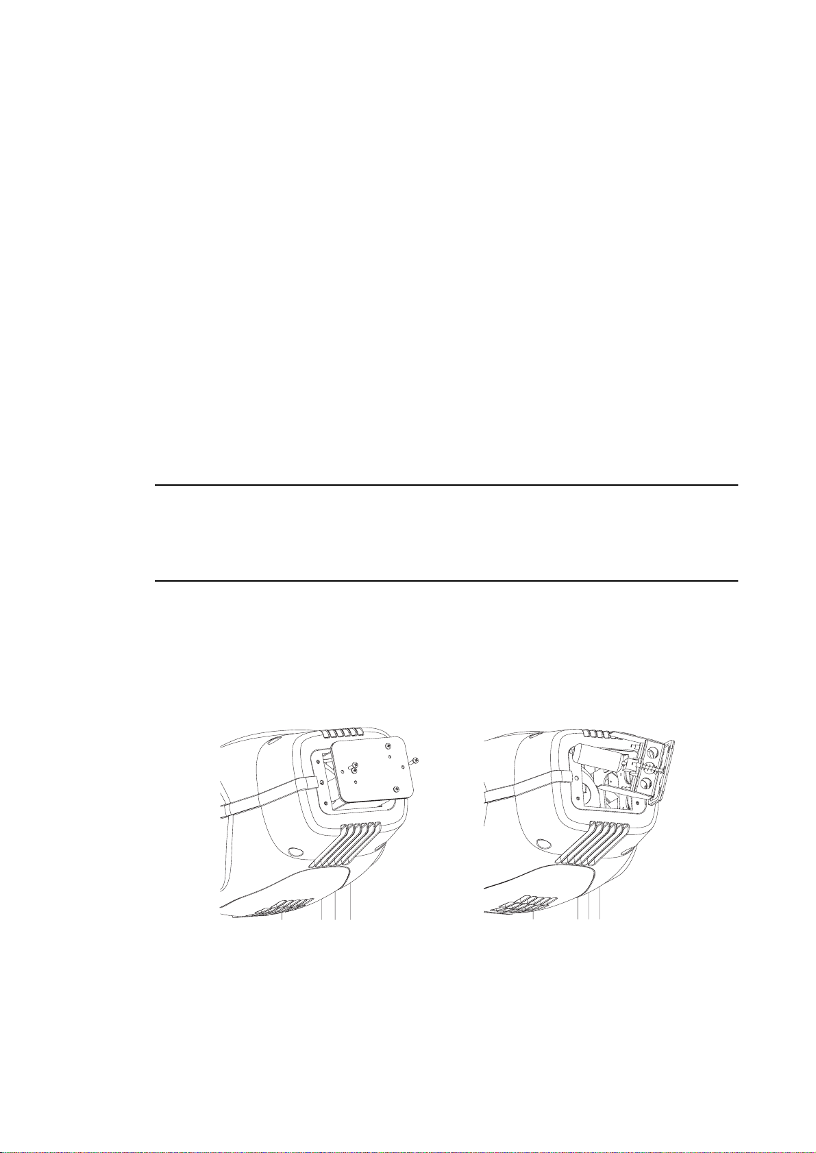
Opening the base
To access base componen ts, rem ove th e 2 cove r plat es from th e top
of the base. Each plate is fastened with 4 screws. 'RQRWUHPRYHWKHFXUYHGSODWHVIURPWKHVLGHRIWKHEDVH
Removing the printed circuit board
1. Disconnect the fixture from AC power. Remove the cover plate from the front of the fixture.
2. Unplug the white plastic wire connectors from the top of the printed circuit board. To unplug a
connector, hold the plastic connector - never pull the wires - and pull it straight off the pins.
3. Grasp the black pins on either end of the circuit board and gently pull it out. You may have to
guide some wires past the motor housing. Be careful not to knock the copper heat sinks.
4. To replace the circuit board, gently put it back in the base. You may have to guide some wires
past the motor housing. Push the black pins down to lock the board in place.
5. Reconnect the wire connectors. The connectors are labelled on the side that faces up, away
from the ICs. The connection order is:
PL551: TILT
PL531: PAN
PL521: DIM
PL511: COL2
PL501: COL1
PL441: ROGO
PL431: GOBO1
PL421: IRIS
6. Replace the cover before applying power.
Maintenance and Basic Service
PL411: FOCUS
PL401: ROPRI
PL701: PRISM
PL301: GOBO2
PL304: 2-pin fan
PL303: FAN
PL203: OPTO2
PL202: OPTO1
PL201: display
21
Page 22

Replacing fuses
The MAC 500/E has 4 fuses. The main fuse is loca ted on the power-switch panel and may be replaced without opening
the fixture.
The fuses for each of t he 3 low-voltage power supplies are located on t he printed circui t board. If one of the circuit
board LEDs does not l ight, one of these fuses may be blown.
1. Remove the printed circuit board.
2. Locate and replace the defective fuse with one of the same rating. The fuses are shown on the
PCB layout diagram and their values are listed in the specifications.
3. Replace the printed circuit board.
Changing the XLR pin-out
1. Remove the printed circuit board.
2. Position the jumpers for the desired XLR pin-out
as shown.
3. Replace the printed circuit board.
Changing voltage and frequency settings
7KHYROWDJHDQG IUHTXHQF\VHWWLQJVPXVW PDWFK WKH ORFDO $& SRZHU VXSSO\ These settings are printed on the serial
number label on the bottom of the base. If the voltage is not within 5 percent of the local supply or the frequency (50/
60 Hz) is different, then the magnetic ballast and/or transformer must be re wired.
MAC 500 with magnetic ballast
1.
Disconnect the MAC 500 from AC power.
2. Find the correct transformer and ballast terminals for your AC supply in the table below. Consult
a qualified electrician if you do not know the AC frequency and voltage.
AC Supply Transformer Magnetic Ballast
Frequency Voltage Voltage Terminal Setting Terminal
50 Hz 200-210 V 210 V 4 200 V / 50 Hz 7
50 Hz 210-220 V 210 V 4 230 V / 50 Hz 10
Remove the top covers.
2
-
3+
2
DMX pin-outMartin pin-out
(default)
-
3+
50 Hz 220-235 V 230 V 6 230 V / 50 Hz 10
50 Hz 235-240 V 230 V 6 245 V / 50 Hz 12
50 Hz 240-260 V 250 V 8 245 V / 50 Hz 12
60 HZ 200-217 V 210 V 4 208 V / 60 Hz 4
60 HZ 217-240 V 230 V 6 227 V / 60 Hz 7
3. Locate the transformer: it is on the left end, near the power switch. Move the BROWN and RED
transformer wires to the correct terminal. The terminal number is printed in front of the connection tab.
4. Locate the magnetic ballast: it is on the opposite end from the transformer, near the control
panel. Move the BROWN ballast wire to the correct terminal. The terminal number is printed in
front of the connection tab.
5. Replace the top covers before applying power.
22
MAC 500/E User Manual
Page 23

MAC 500 E with electronic ballast
Electronic ball ast models t hat come factory set f or 100 V or 120 V have a 10 A main fu se, which is located near the
power switch. Units set at 210 V and above ha ve a 6.3 A main fuse. Use a 6.3 A fuse when the WUDQVIRUPHU is set at
200, 210, 220, 230, or 240 V. Use a 10 A time-delay fuse when it is set at 100, 110, or 120 V.
No rewiring of the electronic EDOODVW is necessary; it work s at any voltag e between 100 an d 250 v olts, a nd at a ny frequency between 50 and 60 Hz. The WUDQVIRUPHU must be tapped for the local supply vo ltage as shown below.
brown
black
black
black
red
brown
red
blue
blue
blue
blue
blue
brown
red
black
7 8 9
6
5
100 V
4
3
1
7 8 9
6
5
210 V
4
3
1
brown
red
blue
blue
blue
blue
blue
brown
red
black
7 8 9
6
5
110 V
4
3
1
7 8 9
6
5
220 V
4
3
1
brown
red
blue
blue
blue
blue
blue
brown
red
black
7 8 9
6
5
120 V
4
3
1
7 8 9
6
5
230 V
4
3
1
blue
blue
blue
blue
black
brown
red
black
7 8 9
6
5
200 V
4
3
1
7 8 9
6
5
240 V
4
3
1
Updating software
The latest software for the MAC 500/E is available from your Martin dealer and the Martin Professional web site.
Please read the update notes bundled with the so ftware. Up date so ftware is u ploa ded to th e M AC 50 0 /E u sin g a Ma rtin
uploader such as the MBPP1, or MP-2.
Normal upload
Connect the uploader to the fixture just like a controller. Under normal conditions, software can be installed from a
remote location - there is no need to set the MAC 500/E to boot mode. Please refer to the uploader manual for further
instructions.
Boot mode upload
If the data is corrupted during transmission, a check-sum error (CSER) will occur and after 15 seconds the fixture will
automatically switch to boot mode (
uploader manual.
If a software upload to the MAC 500/E is interrupted, the fixture must be powered off for at least 10 seconds before a
new upload can be attempted. When powered on, a check-sum error will occur and it will automatically go into boot
mode, ready for a second upload attempt. Select boot mode upload on the uploader.
MAC 500 E
Transformer
Settings
UPLd) and be ready for a boot-mode upload as described below and in the
Maintenance and Basic Service
23
Page 24

If there is no functional software in memory, the fixture must be set to boot mode manually before starting the upload.
If the control panel works, select
[ENTER].
UPLd from the SPEC menu and confirm when SURE is displayed by pressing
If the control panel does not work, boot mode can be engaged by
moving jumper PL12 1 on the mai n circu it board to pins 1 an d 2 as
follows.
1. Remove the printed circuit board. It may not be necessary to unplug the connectors.
2. Position jumper PL121 to upload mode (INIT) as shown. See also the circuit board layout diagram on page 33.
3. Plug in unplugged connectors, apply power to the MAC 500/E
Refer to the uploader manual for instructions.
4. After the upload, disconnect the fixture from the electricity, move the jumper back to the normal
setting, and replace the circuit board.
Changing lenses
Accessory lenses are availabl e to chan ge the stand ard 17° beam an gle to 23.5°. Both the foc us lens and the front le ns
must be changed.
1. Remove the top and bottom head covers.
2. Unscrew and remove the front lens from chassis. Move the dimmer blades out of the way.
3. Slide the focus assembly forward, grasp the focus lens and turn it 60° counterclockwise to
unlock. (A service tool is available, see the list of accessories on page 35.) Pull the lens out of
the moving bracket.
4. Find the small round notch in the rim of the new focus lens. Turn the lens so that the tabs align
with the holes in the bracket and the small notch is at 10 o’clock.
5. Insert the new focus lens squarely into the bracket. Turn the lens 60° clockwise until the locking
spring snaps into the notch in the rim.
6. Set the new front lens on the front of the chassis and replace the screws.
7. Replace the top and bottom covers.
PIN 1
È
PL121 PL121
,
and proceed with the upload.
PIN 1
hard boot settingnormal setting
È
Replacing the lamp
The risk of lamp explosi on increases with lamp hours as th e quartz envelop e gradually weak ens. It is recomme nded
that lamp usage not exceed 12 5 percent of the lamp’s rated average life.
The procedure for installing the lamp is d escribed on pa ge 5. After installing the lamp, reset the lamp usage counter s as
described under “Readouts” on page 14.
24
MAC 500/E User Manual
Page 25

Optimizing lamp alignment
The lamp alignment is set at the factory. If, the light distribution is uneven, lamp align ment ma y be adjuste d as follo ws.
A 3 mm Allen wrench is required.
1. Disconnect the fixture from AC power supply and allow the lamp to cool for 15 minutes.
2. Make a preliminary adjustment: remove the lamp assembly and turn the 3 lamp adjustment
screws to position the lamp-socket plate a distance of 38 mm (1.5”) from the access plate (outside measurement) as shown. Replace the lamp assembly.
lamp adjustment screws (3 m m Allen)
3. Switch on the MAC 500/E and allow it to reset. Using either a controller or the control panel,
strike the lamp and focus the light on a flat surface.
4. Center the hot-spot (the brightest part of the beam) by turning the 3 adjustment screws. Turn
one screw at a time to drag the hot-spot diagonally across the projected image. If there is no
hot-spot, adjust the lamp until the light is even.
5. To reduce a hot-spot, pull the lamp in by turning all three screws clockwise 1/4-turn at a time
until the light is evenly distributed.
6. If the light is brighter around the edge than it is in the center, or if light output is low, the lamp is
too far back in the reflector. “Push” the lamp out by turning the screws counterclockwise 1/4-turn
at a time until the light is bright and evenly distributed.
Installing the optional head shell safety wire
An optional wire (P/N 50 300502) for secondary attachment of the
plastic shells is available. Two wires are required per fixture. The
wire has a closed loop a t one end and a hook at the other end. To
secure the shell:
1. Remove the head shells as described above.
2. Place the closed loop under a washer and screw in the
lamp housing counterweight as shown. Replace the
washer and screw and tighten well.
3. Loop the wire around a cross rib between the shell
ventilation slots and hook the wire to itself. Do not
attach the hook directly to the plastic rib.
Maintenance schedule
The maintenance schedule will depend heavily on the application and should be discussed with your Martin technician. Cleaning, lubricating and servicing the fixture is best left to a qualified technician. He has the knowledge, experience, tools, lubricants and other materials required to keep the MAC 500/E performing at its best.
Maintenance and Basic Service
25
Page 26

Cleaning
Optical components
Be very careful when cleaning the optical components. The colored surface on the dichroic filters is achieved by
means of special multi-layer coatings and even small scratches may be visible. Residues from cleaning fluids can bake
onto componen ts and ruin them.
1. Allow the components to cool completely.
2. Wash dirty lenses and filters with isopropyl alcohol. A generous amount of regular glass cleaner
may also be used, but no residues may remain.
3. Rinse with distilled water. Mixing the water with a small amount of wetting agent such as Kodak
Photoflo will help prevent streaking and spotting.
4. Dry with a clean, soft and lint-free cloth or blow dry with compressed air.
Fans
To ensure proper cooling of the fixtu re, it is important that the fans are free of dust. Vacuum or gently wipe the fans
clean if they are dirty.
Lubrication
Use only Martin silicone lubricant, P /N 37302003 (50 0 ml) or P/N 37 30200 4 (200 ml, in applicato r bottle ), to lubric ate
the MAC 500/E. No other lubricant is appr oved for use. Be caref ul not to get oil on dri ve belts or other parts.
The focus mechanism slides back and forth on 2 meta l pins. These pins must be lubri cat ed pe riodica lly with a drop or
two of silicone oil. Check the focus mec han ism whene ver th e he ad is op en for service and lubricate the slides if move ment is rough or noisy, or if the slides seem dry.
Check the rotatin g-gobo bearings whenever the unit is being serviced and lubricat e them if movement is rough or
noisy. Apply a few drops of oil t o the bea rings from ab ove. Avoid applying exc ess lu brican t and be carefu l not to get
oil on the other parts.
Depending on conditions, these bearings may need to be cleaned and lubricated periodically by a qualified technician.
Apply several drops of
silicone lubricant.
Apply 1 - 2 drops of
silicone lubricant.
26
MAC 500/E User Manual
Page 27

section 7
APPENDICES
DMX protocol
DMX Channel Start code = 0
DMX1 DMX2 DMX3 DMX4
Value Percent Function
Shutter, Strobe, Reset, Lamp On/Off
1
1
If DMX reset is disabled, a reset command may be sent if color wheel 1 set to
cyan 401(144-148) and color wheel 2 is
set to red 308 (157-160).
2
If DMX lamp off is disabled, a lamp off
command may be sent if color wheel 1 is
set to cyan 401 (144-148) and color wheel
2 is set to red 308 (157-160).
2
0 - 19
20 - 49
50 - 72
73 - 79
80 - 99
100 - 119
120 - 127
128 - 147
148 - 167
168 - 187
188 - 190
191 - 193
194 - 196
197 - 199
200 - 202
203 - 207
208 - 217
218 - 227
228 - 237
238 - 247
248 - 255
0 - 255 0 - 100
0 - 16
16 - 32
32 - 48
48 - 64
64 - 80
80 - 96
96 - 112
112 -128
128 - 144
0 - 7
8 - 19
20 - 28
29 - 31
31 - 39
39 - 47
47 - 50
50 - 58
58 - 65
66 - 73
74 - 75
75 - 76
76 - 77
77 - 78
78 - 79
80 - 81
82 - 85
85 - 89
89 - 93
93 - 97
97 - 100
0 - 6
6 - 13
13 - 19
19 - 25
25 - 31
31 - 38
38 - 44
44 - 50
50 - 56
Shutter closed
Shutter open
Strobe, fast
Shutter open, lamp power reduced (MAC 500 E only)
Opening pulse, fast
Closing pulse, fast
Shutter open
Random strobe, fast
Random strobe, medium
Random strobe, slow
Shutter open
Random opening pulse, fast
Random opening pulse, slow
Random closing pulse, fast
Random closing pulse, slow
Shutter open
Reset fixture, see note 1
Shutter open
Lamp power on
Shutter open
Lamp power off: time > 5 seconds, see note 2
Intensity
Æ
0
COLOR 1
Color Scroll
White
Blue 111
Red 301
Magenta 507
Green 202
Yellow 604
Purple 502
Blue 101
Pink 312
100%
Æ
Æ
slow
Blue 111
Æ
Red 301
Æ
Magenta 507
Æ
Green 202
Æ
Yellow 604
Æ
Purple 502
Æ
Blue 101
Æ
Pink 312
Æ
Cyan 401
Æ
Æ
slow
slow
Fixed Colors
3
145 - 148
149 - 152
153 - 156
157 - 160
161 - 164
165 - 168
169 - 172
173 - 176
177 - 180
181 - 184
185 - 215
216 - 245
246 - 255
57 - 58
58 - 60
60 - 61
62 - 63
63 - 64
65 - 66
66 - 67
68 - 69
69 - 71
71 - 72
73 - 84
85 - 96
96 - 100
Appendices
Cyan 401
Pink 312
Blue 101
Purple 502
Yellow 604
Green 202
Magenta 507
Red 301
Blue 111
White
Continuous Rotation
Æ
CW, fast
CCW, slow
Enable alternate color functions on channel 4.
slow
Æ
fast
27
Page 28

DMX Channel Start code = 0
DMX1 DMX2 DMX3 DMX4
Value Percent Function
COLOR 2: Normal Functions
0 - 16
16 - 32
32 - 48
48 - 64
64 - 80
80 - 96
96 - 112
112 -128
128 - 144
145 - 148
149 - 152
4
153 - 156
157 - 160
161 - 164
165 - 168
169 - 172
173 - 176
177 - 180
181 - 184
185 - 215
216 - 245
246 - 248
249 - 251
252 - 255
0 - 6
6 - 13
13 - 19
19 - 25
25 - 31
31 - 38
38 - 44
44 - 50
50 - 56
57 - 58
58 - 60
60 - 61
62 - 63
63 - 64
65 - 66
66 - 67
68 - 69
69 - 71
71 - 72
73 - 84
85 - 96
96 - 97
98 - 98
99 - 100
Color Scroll
White
Æ
CTC 3200-4100
Æ
CTC 3200-4100
CTC 3200-5600
Blue 104
Blue 108
Green 206
Red 308
Yellow 603
CTC 5500-2900
Fixed Colors
CTC 5500-4200
CTC 5500-2900
Yellow 603
Red 308
Green 206
Blue 108
Blue 104
CTC 3200-5600
CTC 3200-4100
White
Continuous Rotation
CW, fast
CCW, slow
Random Color
Fast
Medium
Slow
Alternate Functions (Enable on channel 3.)
Æ
Æ
Æ
Æ
CTC 3200-5600
Æ
Blue 104
Blue 108
Green 206
Æ
Red 308
Yellow 603
Æ
CTC 5500-2900
Æ
CTC 5500-4200
slow
Æ
fast
0-255
0 - 55
56 - 75
76 - 95
96 - 115
5
6
116 - 135
136 - 155
156 - 175
176 - 195
196 - 215
216 - 235
236 - 255
0 - 126
127
128 - 255
0 - 2
3 - 127
128 - 252
253 - 255
0 - 100
0 - 22
22 - 29
30 - 37
38 - 45
45 - 53
53 - 61
61 - 69
69 - 76
77 - 84
85 - 92
93 - 100
0 - 49
50
50 - 100
0 - 1
1 - 50
50 - 98
99 - 100
67 different colors in following order:
white, purple, pink, magenta, red, orange, yellow,
green, cyan, blue, black
Rotating Gobo Selection
Set index, direction, and speed on channel 6.
Open gobo
Gobo 1 - Indexing
Gobo 2 - Indexing
Gobo 3 - Indexing
Gobo 4 - Indexing
Gobo 5 - Indexing
Gobo 5 - Cont. Rotation
Gobo 4 - Cont. Rotation
Gobo 3 - Cont. Rotation
Gobo 2 - Cont. Rotation
Gobo 1 - Cont. Rotation
Rotating Gobo Index and Rotation
Select gobo and function on channel 5.
Indexing
Index CCW
Default index
Index CW
Continuous Rotation
No rotation
CW, slow
CCW, fast
No rotation
Æ
Æ
fast
slow
28
MAC 500/E User Manual
Page 29

DMX Channel Start code = 0
DMX1 DMX2 DMX3 DMX4
Value Percent Function
Fixed Gobos
7
Gobo mode = fixed (default)
7
Gobo mode = scroll (optional)
0 - 9
10 - 19
20 - 29
30 - 39
40 - 49
50 - 59
60 - 69
70 - 79
80 - 89
90 - 102
103 - 119
120 - 136
137 - 153
154 - 170
171 - 187
188 - 204
205 - 221
222 - 238
239 - 255
0 - 180
0
20
40
60
80
100
120
140
160
180
181 - 183
184 - 186
187 - 189
190 - 192
193 - 195
196 - 198
199 - 201
202 - 204
205 - 207
0 - 4
4 - 8
8 - 11
12 - 15
16 - 19
20 - 23
24 - 27
27 - 31
31 - 35
35 - 40
40 - 47
47 - 53
54 - 60
60 - 67
67 - 73
74 - 80
80 - 87
87 - 93
94 - 100
0 - 70
0
8
16
24
31
39
47
55
63
70
71 - 72
72 - 73
73 - 74
74 - 75
75 - 76
77 - 78
78 - 79
79 - 80
80 - 81
Fixed gobo positions
Open gobo
Gobo 1
Gobo 2
Gobo 3
Gobo 4
Gobo 5
Gobo 6
Gobo 7
Gobo 8
Gobo 9
Gobo shake, fast
Gobo 9
Gobo 8
Gobo 7
Gobo 6
Gobo 5
Gobo 4
Gobo 3
Gobo 2
Gobo 1
Fixed Gobos
Continuous scroll
Full positions:
Open
Gobo 1
Gobo 2
Gobo 3
Gobo 4
Gobo 5
Gobo 6
Gobo 7
Gobo 8
Gobo 9
Gobo shake
Gobo 9 shake
Gobo 8 shake
Gobo 7 shake
Gobo 6 shake
Gobo 5 shake
Gobo 4 shake
Gobo 3 shake
Gobo 2 shake
Gobo 1 shake
Æ
slow
208 - 231
232 - 255
8
9
0 - 255 0 - 100
0 - 199
200 - 215
216 - 229
230 - 243
244 - 246
247 - 249
250 - 252
253 - 255
82 - 91
92 - 100
0 - 78
78 - 84
85 - 90
90 - 95
96 - 96
97 - 98
98 - 99
99 - 100
Appendices
Continuous rotation
CW, fast
CCW, slow
Focus
Infinity
Iris
Open
Close
Pulse opening, fast
Pulse closing, fast
Random pulse opening, fast
Random pulse opening, slow
Random pulse closing, fast
Random pulse closing, slow
Æ
Æ
2 meters
Æ
close
slow
Æ
fast
Æ
slow
Æ
slow
29
Page 30

DMX Channel Start code = 0
DMX1 DMX2 DMX3 DMX4
10
Fixture type = prism (default)
10
Fixture type = frost (optional) 0 - 255 0 - 100
11 11 11 11
-12-12
12 13 12 13
-14-14
--1315
Value Percent Function
0 - 19
20 - 79
80 - 89
90 - 149
150 - 215
216 - 220
221 - 225
226 - 230
231 - 235
236 - 240
241 - 245
246 - 250
251 - 255
0 - 255 0 - 100
0 - 255 0 - 100
0 - 255 0 - 100
0 - 255 0 - 100
0 - 2
3 - 245
246 - 248
249 - 251
252 - 255
0 - 2
3 - 239
240 - 242
243 - 245
246 - 248
249 - 251
252 - 255
0 - 7
8 - 31
31 - 35
35 - 58
59 - 84
84 - 86
87 - 88
89 - 90
91 - 92
93 - 94
95 - 96
96 - 98
98 - 100
0 - 1
1 - 96
96 - 97
98 - 98
99 - 100
0 - 1
1 - 94
94 - 95
95 - 96
96 - 97
98 - 98
99 - 100
Prism
Prism off
Rotating prism, CCW fast
No rotation
Rotating prism, CW slow
Prism off
Combined Rotating Prism and Gobo Macros
Macro 1
Macro 2
Macro 3
Macro 4
Macro 5
Macro 6
Macro 7
Macro 8
Variable Frost
No frost
Pan
Left
Pan Fine (LSB)
Left
Tilt
Up
Tilt Fine (LSB)
Up
Pan/Tilt Speed
Tracking
Fast
Tracking, normal speed (override PTSP FAS T )
Tracking, fast speed (override PTSP NORM)
Blackout while moving
Effects Speed
Dimmer, iris, fo cus and gobo in dexing
Tracking mode
Fast
Tracking, normal mode (MOdE = NORM)
Tracking, studio mode (MOdE = STUd)
Tracking, shortcuts disabled (SCUT = OFF)
Tracking, shortcuts enabled (SCUT = ON)
Maximum speed
Æ
full frost
Æ
right (128 = neutral)
Æ
right
Æ
down (128 = neutral)
Æ
down
Æ
slow
Æ
slow
Æ
Æ
fast
slow
n/a n/a 14 16
30
Color 1, color 2, and fixed gobo if
0 - 2
3 - 239
240 - 242
243 - 245
246 - 248
249 - 251
252 - 255
0 - 239
240 - 242
243 - 245
246 - 248
249 - 251
252 - 255
0 - 251
252 - 255
0 - 2
3 - 245
246 - 255
0 - 1
1 - 94
94 - 95
95 - 96
96 - 97
98 - 98
99 - 100
0 - 94
94 - 95
95 - 96
96 - 97
98 - 98
99 - 100
0 - 98
99 - 100
0 - 1
1 - 96
96 - 100
Tracking mode
Speed, fast
Tracking, normal mode (MOdE = NORM)
Tracking, studio mode (MOdE = STUd)
Tracking with shortcuts disabled, overrides SCUT ON
Tracking with shortcuts enabled, overrides SCUT OFF
Blackout while moving
Fixed gobo if gMOd = FIX
Normal (as set on effect channel), no blackout
Tracking, normal mode (MOdE = NORM)
Tracking, studio mode (MOdE = STUd)
Normal, shortcuts disabled, overrides SCUT ON
Normal, shortcuts enabled, overrides SCUT OFF
Blackout while moving
Rotating gobo and prism
Normal (as set on effect channel), no blackout
Blackout while moving
Gobo shake speed if
Fast
Speed, fast
Fast
MAC 500/E User Manual
Æ
Æ
gMOd = SCRL
slow
gMOd = SCRL
slow
Page 31

Messages
Display readout Appears if... What to do
AUTO (Automatic protocol
detection error)
LERR (Lamp error)
MERR (Memory error)
CSER (Check-sum error)
**** ... there is no communication between the
ShER (Short error)
Hot (Hot lamp)
bTER (Base temperature error)
HTER (Head temperature
error)
FbEP (Feedback error pan)
FbET (Feedback error tilt)
FbER (Feedback error pan/tilt)
PAER (Pan time-out)
TIER (Tilt time-out)
C1ER (Color wheel 1 time-out)
C2ER (Color wheel 2 time-out)
FgER (Fixed gobo time-out)
RgER (Rot. gobo time-out)
... automatic proto col detec tion is en abled
but the protocol (Martin/DMX) cannot be
determined because there is no control
data.
... the lamp doesn’t ignite within 10 minutes of receiving the ‘Lamp ON’ command. Likely reasons are a missing or
defective lamp, or insufficient AC voltage.
...the EEPROM memory cannot be read. • Contact Martin service personnel
...a software upload is unsuccessful. • Reload software, see page23.
control panel and motherboard. This
readout appears briefly when switching
on the fixture.
... the fixture detects the lamp is ON but
no ‘Lamp ON’ command has been
received. This can occur if the lamp relay
is stuck or if the lamp-power feedback circuit fails. The fix ture m ay be operated but
remote lamp on/off may be effected.
... you attempt to strike the lamp within 8
minutes after having switched it off. The
fixture will store the ‘Lamp ON’ instruction
and strike the lamp once the 8 minutes
period has elapsed.
...there is a malfunction in the base or
head temperature sensing circuit.
...pan (FbEp), tilt (FbET) or both (FbER)
feedback circuits are malfunctioning. It
will still be possible to operate the fixture,
though it goes into a “safe” mode where
maximum speed is reduced , thus pr eventing the fixture from losing track of its
home position (losing step).
...the pan or tilt indexing circuit is malfunctioning. The fixture will, after the time-out,
establish a mec hanical sto p, and cont inue
to work normally.
...the magnetic-indexing circuit malfunctions (e.g. sensor defective or magnet
missing). After the time-out, the effect in
question stops in a random position.
• Verify that the controller is sending
and the serial link is properly connected.
• Check the lamp
• Check that the voltage and frequency settings match the local
supply.
for assistance.
• Check fuses and replace accordingly.
• Check that cable between control
panel and motherboard is connected properly.
• Reinstall software.
• Contact Martin service personnel
for assistance.
• Wait until the lamp strikes.
• Contact Martin service personnel
for assistance.
• Contact Martin service personnel
for assistance.
• Contact Martin service personnel
for assistance.
• Contact Martin service personnel
for assistance.
Appendices
31
Page 32

Troubleshooting
Problem Probable cause(s) Remedy
One or more of the fixtures
is completely dead.
Fixtures reset correctly but
all respond erratically or not
at all to th e controller.
Fixtures reset correctly but
some respond erratically or
not at all to the controller.
Magnetically indexed effect
resets correctly but wanders
after fixture reaches operating temperature.
Mechanical effect loses
position.
Lamp fails to strike after
turning the fixture off and on
again, or after a power failure. (MAC 500 E)
No light and “LERR” error
message displayed.
Lamp cuts out intermittently.
No power to fixture.
Primary fuse blown (l ocated a t the ma ins
inlet cable).
Secondary fuse(s) blown (located on
PCB inside base).
The controller is not connected. Connect controller.
XLR pin-out of the controller does not
match pin-out of the first fixture on the
link (i.e. signal is reversed).
Bad data link connection
Data link not terminated with 120Ω termi-
nation plug.
Incorrect addressing of the fix tures. Check fixture address and protocol settings.
One of the fixtures is defective and disturbs data transmission on the link.
XLR pin-out on fixtures does not match
(pins 2 and 3 reversed).
Effect wheel or magnetic sensor requi res
mechanical adjustment.
The transformer setting does not match
local voltage.
Mechanical train requires cleaning,
adjustment, or lubrication.
Electronic ballast does not recognize
that the lamp is off.
The ballast and transformer settings do
not match local AC voltage and frequency.
Lamp blown Disconnect fixture and replace lamp.
Lamp not installed Disconnect fixture and install lamp.
Fixture is too hot.
The ballast and transformer settings do
not match local AC voltage and frequency.
Check that power is switched on and cables
are plugged in.
Disconnect fixture and replace fuse.
Disconnect fixture. Check fuses on PCB and
replace.
Install a phase-reversing cable between the
controller and the first fixture on the link.
Inspect connections a nd cables. Correct poor
connections. Repair or replace damaged
cables.
Insert termination plug in output jack of the
last fixture on the link.
Bypass one fixt ure at a time until normal operation is re gained: unplug the XLR in and out
connectors and connect them directly
together. Have th e fixture serviced by a qualified technician.
Install a phase-reversing cable between the
fixtures or swap pins 2 and 3 i n the fixtu re that
behaves erratically.
Disable effects feedback (page 13). Contact
Martin technician for service.
Disconnect fixture. Check transformer setting
and correct if necessary.
Contact Martin technician for service.
Send LAMP OFF command before sending
another LAMP ON command. The lamp will
strike after an 8 m inute d elay. See protocol for
override if dLOF is set to OFF
Disconnect fixture. Check ballast and transformer settings and correct if necessary.
Allow fixture to cool.
Reduce ambient room temperature.
Recalibrate temperature sensors.
Disconnect fixture. Check ballast and transformer settings and correct if necessary.
32
MAC 500/E User Manual
Page 33

Circuit board layout
MAINS IN
MAINS OUT (TO BALLAST IN)
LAMP FEEDBACK
MAGNETIC SENSORS
PAN/TILT INDEX SWITCES
HARD BOOT JUMPER
SERIAL DATA LINK
XLR PIN-OUT JUMPER
CONTROL MODULE
TILT FEEDBACK
PAN FEEDBACK
FAN (HEAD) + TEMP SENSE
FAN (BASE)
GOBO 2
PRISM
ROT. PRISM
FOCUS
IRIS
GOBO 1
AC IN
ROT. GOBO
COLOR 1
COLOR 2
DIMMER
PAN
TILT
Appendices
33
Page 34

Specifications
Measurements
• Length...........................................................................................................................................356 mm (14.0 in)
• Width........................................ .... .... ... .... ... .......................... ......................... ............................. ..481 mm (18.9 in)
• Height (head at tilt limit)..............................................................................................................673 mm (26.5 in)
• Weight, MAC 500.........................................................................................................................32.8 kg (72.1 lbs)
• Weight, MAC 500 E....................................... .... ......................... .................................................26.1 kg (57.4 lbs)
Electrical, MAC 500
• Ballast taps........................................................................................200/230/245V @ 50 Hz; 208/227V @ 60 Hz
• Power and current*..............................................750 W, 3.4 A @ 230 V / 50 Hz; 750 W, 4.3 A @ 208 V / 60 Hz
• Power factor (PF)*.............................................................................................................................................0.85
Electrical, MAC 500 E
• Transformer taps........................... .... ... .... ...................................100/110/1 20 /2 00/ 2 10/22 0 /23 0/240 @ 50 - 60 Hz
• Power and current*................................................................................................. 690 W, 3.2 A @ 230 V / 50 Hz
• Power factor (PF)*.............................................................................................................................................0.94
Fuses
• Main fuse, MAC 500, MAC 500 E wired between 200 - 240 V............. time-delay 6.3 A / 250 V, P/N 05020020
• Main fuse, MAC 500 E wired between 100 - 120 V.............................time-delay 10.0 A / 250 V, P/N 05020025
• Fuse F601 ............................................................................................... time-delay 5.0 A / 250 V, P/N 05020018
• Fuse F602................................................................................................ time-delay 4.0 A / 250 V, P/N 05020016
• Fuse F603............................................................................................ time-delay 0.315 A / 250 V, P/N 0502 0004
Communication
• Hardware standard........................................................................................................................................ RS-485
• Protocols..................................................................................................USITT DMX512 (1990) / Martin RS-485
• DMX start code ................................... .... ......................... .......................... .............................................................0
• Recommended cable..........................................24 AWG (min.), low capacitance, 85-150 Ω shielded twisted pair
• Connector type......................................... 3-pin XLR male/female (pin 1 = screen, pins 2 and 3 configurable +/-)
Compatible lamps
• Osram HSR-575/2..........................................................575 W, 85 lm/W, 1000 h avg. life, 6000K, P/N 97010200
• Osram HSD-575.............................................................575 W, 78 lm/W, 3000 h avg. life, 7200K, P/N 97010207
• Philips MSD-575............................................................575 W, 75 lm/W, 2000 h avg. life, 5700K, P/N 97010202
• Philips MSR-575/2.........................................................575 W, 85 lm/W, 1000 h avg. life, 6100K, P/N 97010201
Photometric
• Center intensity w/ standard 17° lens set ....................................................................................... .... ..... 246,000 cd
• Center intensity w/ optional 23.5° lens set .............................................................................................134,000 cd
• Total integrated luminous flux (with standard lens, MSR 575/2)................................................................9000 lm
Thermal
• Maximum ambient temperature....................................................................................................... 40° C (104° F)
• Maximum surface temperature under normal operating conditions.................................................80° C (176° F)
34
MAC 500/E User Manual
Page 35

Accessories
Please see the online gobo catalog at http://www.martin.dk for additional gobos available from Martin.
• Outdoor Protection Dome................................... ......................... ....................................................... ... ....90525010
• MPBB1 Uploader.................................... ... .... .......................... ......................... ............................. .... ... ....90758410
• MP-2 Uploader.................................... .... ......................... .......................... ................................ ...............90758420
• Double unit MAC 500/600 flight case......................................................................................................91510002
• Optional wide angle (23.5°) lens set w/ bayonet-mount focus lens..........................................................91610015
• MAC 500 focus lens retrieval tool ..................................................... .......................................................50521600
• Frost filter for MAC 500/RS 918, assembled............................................................................................ 91611003
• G-clamp.....................................................................................................................................................91602003
• Half-coupler clamp..................................... .... .... ......................... .......................... ................................ ....91602005
• Safety wire for head shell (1 piece required for each shell)...................................................................... 50300502
• Retention spring for rotating-gobo holder.................................................................................................17760040
• Rotating-gobo holder.................................................................................................................................17320090
• Retention spring for rotating gobo.............................................................................................................17760210
Appendices
35
Page 36

P/T
-
EED
S
P
14 16
1212 1313
13 15
-1414
--
11
S
optional
10
E
ECT
F
F
default
9
optional
8
7
G
OBO
S
default
5
6
4
C
OLO
R
GHT
L
I
M
2
3
1
ODE
3142
1212
Alternate function (ena bl e on ch. 3) 67 colors: white, purpl e , pi nk, m age nt a, red, orange, yellow, green, cyan, blue, black
white ctc+ ctc++ blue 104 blue 10 8 green 206 red 30 8 yellow 603 ctc-- ctc-
0 14416 32 48 64 80 96 112 128
145 149 153 157 161 165 169 173 177 181
987* 432105
185 ← 215 216 → 245 f
cw ccw
ms
C
OLO
R
C
ONTINUOUS
C
OLOR
S
CROLL
(
WHEEL
2)
S
TEPPED
S
CROLL
C
ONTINUOUS
R
OTATION
R
ND
0 14416 32 48 64 80 96 112 128
145
149 153 157 161 165 169 173 177 181
185 ← 215
216 → 245
255246
white blue 111 red 301 magenta 507 green 202 yellow 604 purple 502 blue 101 pink 312 cyan 401
* 876 432105
cw ccw
closed open
position 9 1 2 3 4 5 6 7 8
C
ONTINUOUS
C
OLOR
S
CROLL
(
WHEEL
1)
D
IMMER
S
TEPPED
S
CROLL
C
ONTINUOUS
R
OTATION
C
A
H
LT
. 4
019
closed
S
20 49
HUTTER
open
50 ← 72
S
TROBE
LOW
PWR
(E)
80 ← 99
opening closing
D
IMMER
100 ← 119
P
ULSE
O
N
E
P
128 187
fast
147 148 168167
R
ANDOM
med slow
S
TROBE
O
N
E
P
R
open close
f
ND
s
PULSE
fs
O
N
E
P
R
ESET
*
217208
O
PEN
227218
L
O
AMP
237228
N
238247
O
PEN
O
> 5 sec.
L
AMP
FF
255248
*
Implemented from CPU software version 1.8
25 50 75 100 125 150 175 200 225 250
Start code = 0
MAC 500 DMX Protocol
open
close
closed
opening
closing
random
infinity 2 meters
0
open
09
10 19
20
G 1
20 29
30 39
40
G 2
40 49
50 59
60
G 3
60 69
S
TATIC
70 79
G
OBO
80
G 4
80 89
S
CROLL
90 102
(
100
G 5
CONTINUOUS
I
RIS
120
F
OCUS
140
103 119
←←←←←←←←←
)
G 6
120 136
G 7
137 153
open
G 1
G 2
G 3
G 4
G 5
G 6
G 7
G 8
G 9
G 9
G 8
G 7
st
S
TATIC
G
OBO
S
CROLL
(
STEPPED
)
128 ← continuous ccw 2523 continuous cw → 127
0
index ccw index cw
G
OBO
127
R
OTATION
128 255
0
55
56 76
75 95 96
115 116
135 136
G 1
G 2
G 3
G 4
G 5
O
O
PEN
PEN
I
NDEXED
G
OBO
S
ELECTION
155 176 195 196 215 216
G 8
154 170
G 6
S
TATIC
160
171 187
G 9
180
987654321
G
OBO
S
HAKE
188 204
G 5
G 4
G
OBO
S
HAKE
156
G 5
175
G 4 G 3
R
OTATING
G
C
cw ccw
205 221
G 3
ONTINUOUS
208 ← 231 232 → 255
222 238
I
RIS
P
ULSE
R
OTATION
G 2
239 255
G 1
st
OBO
S
ELECTION
G 2
235 236
G 1
255
T
0
T 239
0
3 fdimmer, iris, focus, and gobo indexing
3
T P
3 fast slow 245
up down
off full
019
0
left right
out
19
20 ← 79
10 20 30 40 50 60 70 80 90
colors
ccw rotation
80
stop
89
90 → 149
P
RISM
cw rotation
F
ROST
150
no changefixed gobos
no changerotating prism an d gobo
«·» : blackout speed
← : variable speed, points to fast
E
T
ILT
F
INE
(LSB)up down
T
ILT
P
AN
F
INE
(LSB)left right
P
AN
FFECTS
AN
/T
ILT
←
←
S
S
PEED
PEED
M
* Set ch. 3 + ch. 4 as shown to override disabled function.
T : tracking mode
Ts : PTSP= SLOW or SCUT =OFF, T
N
: MOdE=NORM, M
S
: MOdE=STUd
out
F
: PTSP=FAST or SCUT= ON
199
200 215
215
1212345678
M
ACROS
216
←
229
230
←
243
o
f
o
s
c
f
c
s
216
221 226 231 236 241 246 251
239 S F
239
M
M
M
N
N
N
M
M
M
S
S
S
T
251
S
T
F
«·»
«·»
«·»
T
T
S
S
T
T
F
F
«·»
Page 37

Page 38

Unit C6, Hastingwood Trading Estate
Phone 020 8803 7400 email office@gradav.co.uk
35, Harbet Road, London, N18 3HU
FAX 020 8803 5060 Web www.gradav.co.uk
 Loading...