

Page 1
MAC 301 Wash
user manual
TM
Page 2
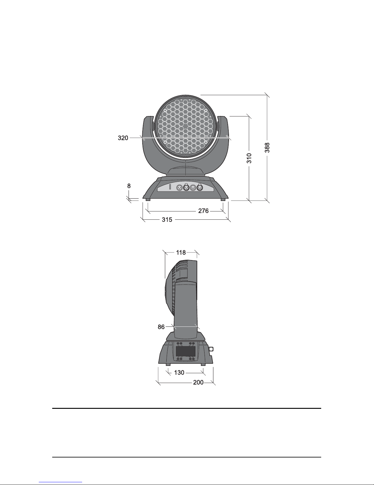
Dimensions
All dimensions are in millimeters
©2009-2010 Martin Professional A/S. Information subject to change without notice. Martin Professional A/S and all affiliated compa-
nies disclaim liability for any injury, damage, direct or indirect loss, consequential or economic loss or any other loss occasioned by
the use of, inability to use or reliance on the information contained in this manual. The Martin logo, the Martin name and all other
trademarks in this document pertaining to services or products by Martin Professional A/S or its affiliates and subsidiaries are trade-
marks owned or licensed by Martin Professional A/S or its affiliates or subsidiaries. The use of certain patents in MAC 301 Wash
products is licensed by Color Kinetics, Inc. (see details printed on product).
P/N 35000228, Rev. F
Page 3
Safety Information 3
Safety Information
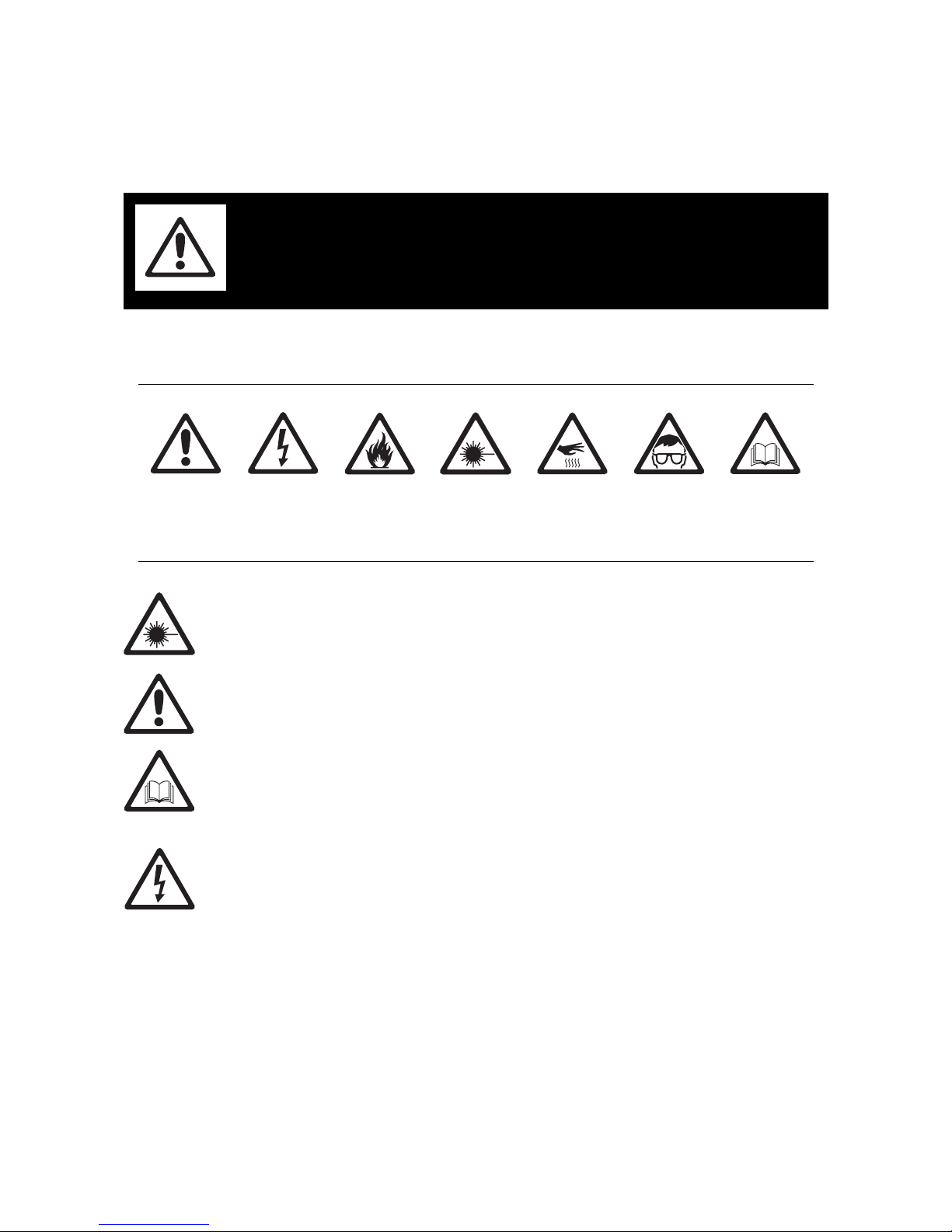
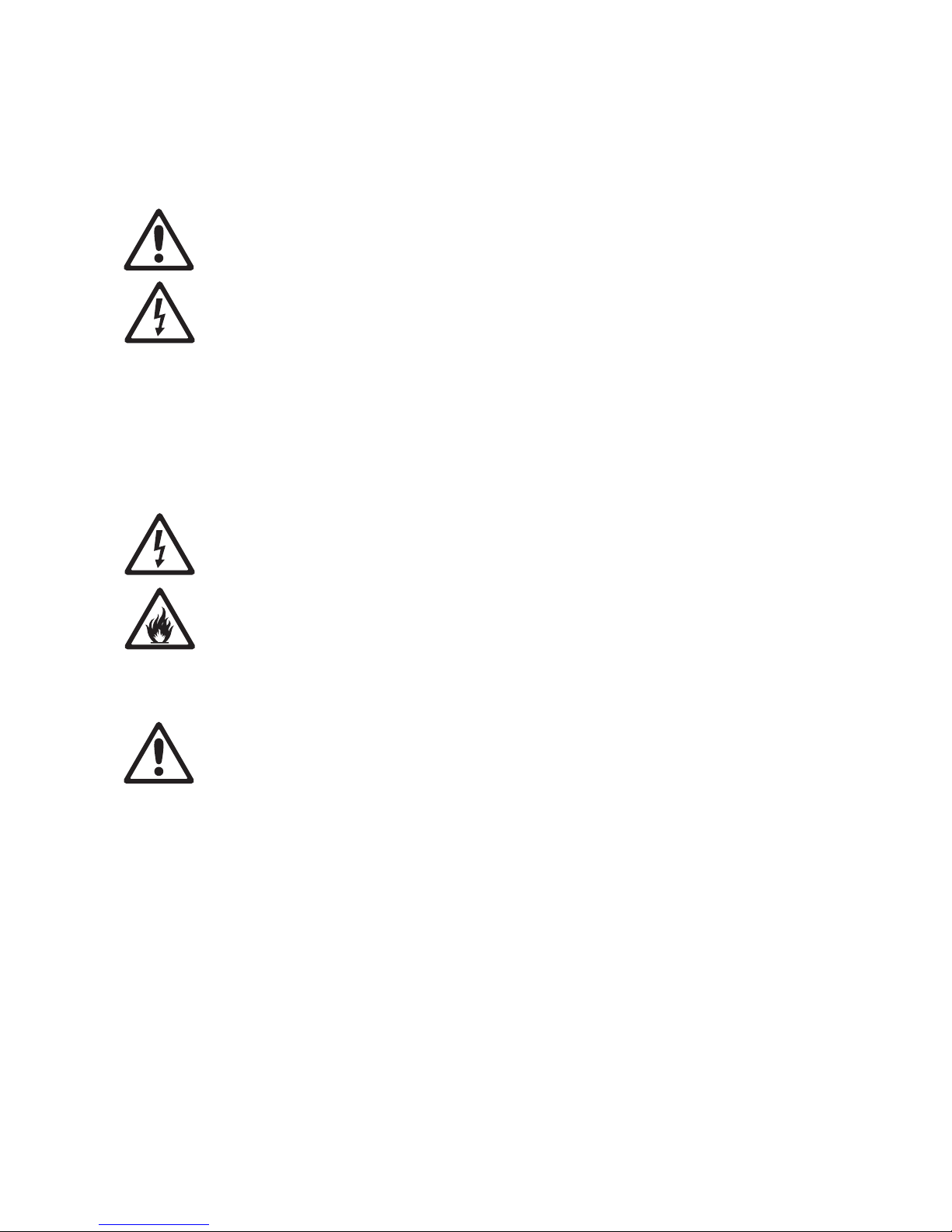
The following symbols are used to identify important safety information on the product and in this manual:
Warning! Risk Group 3 (high risk) LED product according to EN 62471. Do not look into the beam at
a distance of less than 0.5 meters (20 inches) from the front surface of the product. Do not view the
light output with optical instruments or any device that may concentrate the beam.
This product is for professional use only. It is not for household use.
This product presents risks of severe injury or death due to fire and burn hazards, electric shock and falls.
Read this manual before installing, powering or servicing the fixture, follow the safety precautions listed
below and observe all warnings in this manual and printed on the fixture. If you have questions about how to
operate the fixture safely, please contact your Martin supplier or call the Martin 24-hour service hotline on
+45 8740 0000, or in the USA on 1-888-tech-180.
PROTECTION FROM ELECTRIC SHOCK
• Disconnect the fixture from AC power before removing or installing any cover or part – including fuses –
and when not in use.
• Always ground (earth) the fixture electrically.
• Use only a source of AC power that complies with local building and electrical codes and has both
overload and ground-fault (earth-fault) protection.
• Before using the fixture, check that all power distribution equipment and cables are in perfect condition
and rated for the current requirements of all connected devices.
• Isolate the fixture from power immediately if the power plug or any seal, cover, cab le , or other component
is damaged, defective, deformed, wet or showing signs of overheating. Do not reapply power until repairs
have been completed.
• Do not expose the fixture to rain or moisture.
• Refer any service operation not described in this manual to a qualified technician.
• Socket outlets used to supply MAC 301 Wash fixtures with power or external power switches must be
located near the fixtures and easily accessible so that the fixtures can easily be disconnected from power.
WARNING!
Read the safety precautions in this section before
installing, powering, operating or servicing this
product.
DANGER!
Safety hazard.
Risk of severe
injury or death.
DANGER!
Hazardous
voltage. Risk of
lethal or severe
electric shock.
WARNING!
Fire hazard.
WARNING!
LED light
emission. Risk of
eye injury.
WARNING!
Burn hazard. Hot
surface. Do not
touch.
WARNING!
Wear protective
eyewear.
WARNING! Refer
to user manual.
Page 4

4 MAC 301 Wash user manual
PROTECTION FROM BURNS AND FIRE
• Do not operate the fixture if the ambient temperature (Ta) exceeds 40° C (104° F).
• The exterior of the fixture becomes hot during use. Avoid contact by persons and materials. Allow the
fixture to cool for at least 10 minutes before handling.
• Keep all combustible materials (e.g. fabric, wood, paper) at least 100 mm (4 ins.) away from the head.
• Keep flammable materials well away from the fixture.
• Ensure that there is free and unobstructed airflow around the fixture.
• Do not illuminate surfaces within 250 mm (10 ins.) of the fixture.
• Do not attempt to bypass thermostatic switches or fuses. Replace defective fuses with ones of the
specified type and rating.
• Do not stick filters, masks or other materials onto any optical component.
• Do not modify the fixture in any way not described in this manual
• Install only genuine Martin parts.
PROTECTION FROM INJURY
• Do not look continuously at LEDs from a distance of less than 0.5 meters (20 inches) from the front
surface of the fixture without protective eyewear such as shade 4-5 welding goggles. At less than this
distance, the LED emission can cause eye injury or irritation. At distances of 0.5 meters (20 inches) and
above, light output is harmless to the naked eye provided that the eye’s natural aversion response is not
overcome.
• Do not look at LEDs with magnifiers, telescopes, binoculars or similar optical instruments that may
concentrate the light output.
• Ensure that persons are not looking at the LEDs from within 0.5 meters (20 inches) when the product
lights up suddenly. This can happen when power is applied, when the product receives a DMX signal,
when a stand-alone program suddenly increases light output intensity or when SERVICE menu items are
selected.
• Install as described in this manual a secondary attachment such as a safety cable that is approved by an
official body such as TÜV as a safety attachment for the weight of all the fixtures it secures. The safety
cable must comply with EN 60598-2-17 Section 17.6.6 and be capable of bearing a static suspended load
ten times the weight of the fixture.
• If suspending from a rigging structure, attach the fixture with two evenly spaced clamps. Do not use only
one clamp.
• Ensure that any supporting structure and/or hardware used can hold at least 10 times the weight of all the
devices they support.
• Allow enough clearance around the head to ensure that it cannot collide with an object or another fixture
when it moves.
• Check that all external covers and rigging hardware are securely fastened.
• Block access below the work area and work from a stable platform whenever installing, servicing or
moving the fixture.
• Do not operate the fixture with missing or damaged covers, shields or any optical component.
Page 5

Contents
Dimensions . . . . . . . . . . . . . . . . . . . . . . . . . . . . . . . . . . . . . . . . . . . . . . . . . . . . . . . . . . . . . . . . . . . . . . . . 2
Safety Information. . . . . . . . . . . . . . . . . . . . . . . . . . . . . . . . . . . . . . . . . . . . . . . . . . . . . . . . . . . . . . . . . . 3
Fixture overview . . . . . . . . . . . . . . . . . . . . . . . . . . . . . . . . . . . . . . . . . . . . . . . . . . . . . . . . . . . . . . . . . . . 6
Introduction . . . . . . . . . . . . . . . . . . . . . . . . . . . . . . . . . . . . . . . . . . . . . . . . . . . . . . . . . . . . . . . . . . . . . . . . 7
Unpacking . . . . . . . . . . . . . . . . . . . . . . . . . . . . . . . . . . . . . . . . . . . . . . . . . . . . . . . . . . . . . . . . . . . . . . . . 7
Using for the first time . . . . . . . . . . . . . . . . . . . . . . . . . . . . . . . . . . . . . . . . . . . . . . . . . . . . . . . . . . . . . . . 7
AC power. . . . . . . . . . . . . . . . . . . . . . . . . . . . . . . . . . . . . . . . . . . . . . . . . . . . . . . . . . . . . . . . . . . . . . . . . . 8
Main fuse. . . . . . . . . . . . . . . . . . . . . . . . . . . . . . . . . . . . . . . . . . . . . . . . . . . . . . . . . . . . . . . . . . . . . . . . . 8
Power voltage . . . . . . . . . . . . . . . . . . . . . . . . . . . . . . . . . . . . . . . . . . . . . . . . . . . . . . . . . . . . . . . . . . . . . 8
Power cables and power plug . . . . . . . . . . . . . . . . . . . . . . . . . . . . . . . . . . . . . . . . . . . . . . . . . . . . . . . . . 8
Data link. . . . . . . . . . . . . . . . . . . . . . . . . . . . . . . . . . . . . . . . . . . . . . . . . . . . . . . . . . . . . . . . . . . . . . . . . . 10
Tips for reliable data transmission. . . . . . . . . . . . . . . . . . . . . . . . . . . . . . . . . . . . . . . . . . . . . . . . . . . . . 10
Connecting the data link . . . . . . . . . . . . . . . . . . . . . . . . . . . . . . . . . . . . . . . . . . . . . . . . . . . . . . . . . . . . 10
Physical installation . . . . . . . . . . . . . . . . . . . . . . . . . . . . . . . . . . . . . . . . . . . . . . . . . . . . . . . . . . . . . . . 11
Placing the fixture on a flat surface . . . . . . . . . . . . . . . . . . . . . . . . . . . . . . . . . . . . . . . . . . . . . . . . . . . . 11
Mounting the fixture on a truss . . . . . . . . . . . . . . . . . . . . . . . . . . . . . . . . . . . . . . . . . . . . . . . . . . . . . . . 11
Setup. . . . . . . . . . . . . . . . . . . . . . . . . . . . . . . . . . . . . . . . . . . . . . . . . . . . . . . . . . . . . . . . . . . . . . . . . . . . . 12
Control panel and menu navigation. . . . . . . . . . . . . . . . . . . . . . . . . . . . . . . . . . . . . . . . . . . . . . . . . . . . 12
Restoring factory default settings . . . . . . . . . . . . . . . . . . . . . . . . . . . . . . . . . . . . . . . . . . . . . . . . . . . . . 13
DMX address setting . . . . . . . . . . . . . . . . . . . . . . . . . . . . . . . . . . . . . . . . . . . . . . . . . . . . . . . . . . . . . . . 13
DMX modes. . . . . . . . . . . . . . . . . . . . . . . . . . . . . . . . . . . . . . . . . . . . . . . . . . . . . . . . . . . . . . . . . . . . . . 13
Tailoring performance . . . . . . . . . . . . . . . . . . . . . . . . . . . . . . . . . . . . . . . . . . . . . . . . . . . . . . . . . . . . . . 13
Effects. . . . . . . . . . . . . . . . . . . . . . . . . . . . . . . . . . . . . . . . . . . . . . . . . . . . . . . . . . . . . . . . . . . . . . . . . . . . 15
DMX operation. . . . . . . . . . . . . . . . . . . . . . . . . . . . . . . . . . . . . . . . . . . . . . . . . . . . . . . . . . . . . . . . . . . . 16
Stand-alone operation. . . . . . . . . . . . . . . . . . . . . . . . . . . . . . . . . . . . . . . . . . . . . . . . . . . . . . . . . . . . . 17
Programming stand-alone operation . . . . . . . . . . . . . . . . . . . . . . . . . . . . . . . . . . . . . . . . . . . . . . . . . . . 17
Master-slave stand-alone operation . . . . . . . . . . . . . . . . . . . . . . . . . . . . . . . . . . . . . . . . . . . . . . . . . . . 18
Service and maintenance. . . . . . . . . . . . . . . . . . . . . . . . . . . . . . . . . . . . . . . . . . . . . . . . . . . . . . . . . . 19
Cleaning. . . . . . . . . . . . . . . . . . . . . . . . . . . . . . . . . . . . . . . . . . . . . . . . . . . . . . . . . . . . . . . . . . . . . . . . . 19
Control menu service utilities. . . . . . . . . . . . . . . . . . . . . . . . . . . . . . . . . . . . . . . . . . . . . . . . . . . . . . . . . 20
Fixture readouts. . . . . . . . . . . . . . . . . . . . . . . . . . . . . . . . . . . . . . . . . . . . . . . . . . . . . . . . . . . . . . . . . . . 21
Lubrication. . . . . . . . . . . . . . . . . . . . . . . . . . . . . . . . . . . . . . . . . . . . . . . . . . . . . . . . . . . . . . . . . . . . . . . 21
Fuse replacement . . . . . . . . . . . . . . . . . . . . . . . . . . . . . . . . . . . . . . . . . . . . . . . . . . . . . . . . . . . . . . . . . 21
Diagnostic feedback . . . . . . . . . . . . . . . . . . . . . . . . . . . . . . . . . . . . . . . . . . . . . . . . . . . . . . . . . . . . . . . 21
DMX protocol . . . . . . . . . . . . . . . . . . . . . . . . . . . . . . . . . . . . . . . . . . . . . . . . . . . . . . . . . . . . . . . . . . . . . 22
Onboard control menus. . . . . . . . . . . . . . . . . . . . . . . . . . . . . . . . . . . . . . . . . . . . . . . . . . . . . . . . . . . . 24
Troubleshooting . . . . . . . . . . . . . . . . . . . . . . . . . . . . . . . . . . . . . . . . . . . . . . . . . . . . . . . . . . . . . . . . . . 25
Specifications. . . . . . . . . . . . . . . . . . . . . . . . . . . . . . . . . . . . . . . . . . . . . . . . . . . . . . . . . . . . . . . . . . . . . 26
Page 6
6 MAC 301 Wash user manual
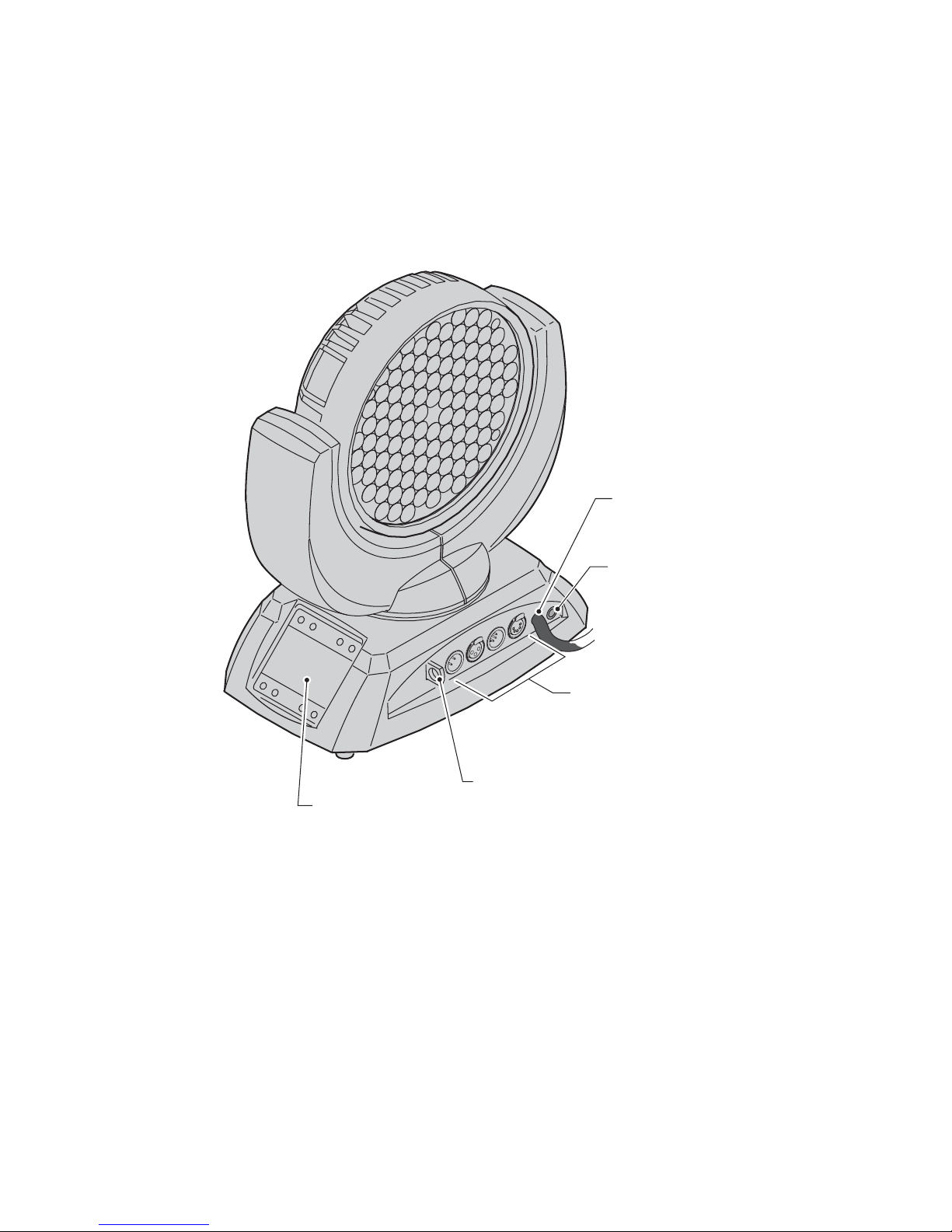
Fixture overview
Power cable entry
Fuseholder
DMX in/out connectors
Safety cable attachment point
Control panel / display
Figure 1: Connections panel overview
Page 7

Introduction 7
Introduction
Thank you for selecting the MA C 301 Wash™, an intelligent lighting fixture from Martin Professional™. This
LED-based moving-head washlight features:
• Luxeon Rebel high-power emitters
• DMX control and stand-alone operation with scenes programmed on fixture or captured via DMX
• Onboard control panel and backlit LCD graphic display
• RGB color mixing with CTC
• ‘Color wheel’ color-snap feature
• Smooth electronic dimming
• Electronic strobe with pulse effects
• Motorized zoom, 13° - 36°
• 430° pan and 300° tilt ranges
• Two 8-bit and two 16-bit DMX control modes
For the latest firmware updates, documentation, and other information about this and all Martin Professional
products, please visit the Martin website at http://www.martin.com
Comments or suggestions regarding this document may be e-mailed to service@martin.dk or posted to:
Technical Documentation
Martin Professional A/S
Olof Palmes Allé 18
DK-8200 Aarhus N
Denmark
Warning! Read “Safety Information” on page 3 before installing, powering, operating or servicing
the MAC 301 Wash.
Unpacking
The following items are included with the MAC 301 Wash:
• Two clamp attachment brackets with quarter-turn fasteners.
• This user manual.
Using for the first time
Before applying power to the fixture:
• Check the Martin Professional websi te at www.martin.com for the mo st rece n t use r do cu me nt ation and
technical information about the MAC 301 Wash. Martin user manual revisions are identified by the
revision letter at the bottom of page 2.
• Carefully review “Safety Information” on page 3.
• Check that the fixture’s power voltage and frequency ranges match the local AC mains power source.
• If drawing power from a socket, install a suitable power plug on the power cable as described in “Power
cables and power plug” on page 8.
Page 8
8 MAC 301 Wash user manual
AC power
Warning! Read “Safety Information” starting on page 3 before connecting the MAC 301 Wash to AC
mains power.
For protection from electric shock, the MAC 301 Wash must be grounded (earthed). The power
distribution circuit must be equipped with a fuse or circuit breaker and ground-fault (earth-fault)
protection.
The MAC 301 Wash does not have a power on/off switch. Socket outlets or external power switch es
used to supply the MAC 301 W ash with power m ust be located near the fixture and easily accessible
so that the fixtures can easily be disconnected from power.
Important! Do not use an external dimming system to supply power to the MAC 301 Wash, as this
may cause damage to the fixture that is not covered by the product warranty.
The MAC 301 Wash can be hard-wired to a building electrical installation if you want to install it
permanently, or a power plug can be installed on the power cable in the case of temporary installation.
Main fuse
Warning! Replace fuses with ones of the same type and rating only.
MAC 301 Wash EU and US models are protected by a 6.3 amp slow-blow main fuse. The main fuse is
located in a fuseholder on the connections panel next to the power cable entry. See “Fuse replacement” on
page 21 for details of accessing and changing fuses.
Power voltage
Warning! Check that the voltage range specified on the fixture’s serial number label
matches the local AC mains power voltage before applying power to the fixture.
MAC 301 Wash EU and US models accept AC mains power at 100-240 V nominal, 50/60 Hz. Do not apply
AC mains power to the fixture at any other voltage than that specified on the fixture’s serial number label.
Power cables and power plug
The MAC 301 Wash is supplied with a hard-wired power cable that can either be permanently connected to
a building’s electrical installation circuits (in this case an external power switch must be installed close to the
fixture) or fitted with a power plug that is suitable for the local AC mains power outlets.
• MAC 301 Wash EU models have an EU color-coded power cable.
• MAC 301 Wash US models have a US color-coded power cable.
These color codes are listed in Table 1 on page 9.
If you decide to install a power plug on the fixture’s po w er cab le , install a grounding-type (earthed) plug that
is correctly rated for the current and power requirements of the fixture. Follow the plug manufacturer’s
instructions. Table 1 shows standard wire color-coding schemes and some possible pin identification
Page 9

AC power 9
schemes; if pins are not clearly identified, or if you have any doubts about proper installation, consult a
qualified electrician.
Wire Color
(EU models)
Wire Color
(US models) Conductor Symbol Screw (US)
brown black live L yellow or brass
blue white neutral N silver
yellow/green green ground (earth) or green
Table 1: Wire color-coding and power connections
Page 10

10 MAC 301 Wash user manual
Data link
A data link is required in order to control a MAC 301 Wash via DMX.
The MAC 301 Wash has both 3-pin and 5-pin XLR connectors for DMX data input and output. The pin-out
on all connectors is pin 1 = shield, pin 2 = cold (-), and pin 3 = hot (+). Do not use the outputs to split the
DMX link.
Pins 4 and 5 in the 5-pin XLR connectors not used in the MAC 301 Wash but are available for possible
additional data signal requirements. Standard pin-out is pin 4 = data 2 cold (-) and pin 5 = data 2 hot (+).
Sockets are wired in parallel: both inputs connect to both outputs.
Tips for reliable data transmission
• Use shielded twisted-pair cable designed for RS-485 devices: standard microphone cable cannot transmit
control data reliably over long runs. 24 AWG cable is suitab le for runs up to 300 meters (1000 ft). Heavier
gauge cable and/or an amplifier is recommended for longer runs.
• Never use both a fixture’ s outputs to split a DMX link. To split the link into branches, use a splitter such as
the Martin 4-Channel Opto-Isolated RS-485 Splitter/Amplifier.
• Do not overload the link. Up to 32 devices may be connected on a serial link.
• Terminate the link by installing a termination plug in the output socket of the last
fixture. The termination plug, which is a male XLR plug with a 120 Ohm, 0.25
Watt resistor soldered between pins 2 and 3, “soaks up” the control signal so it
does not reflect and cause interference. If a splitter is used, terminate each
branch of the link.
Connecting the data link
1. Connect the DMX data output from the controller to the MAC 301 Wash’s 3-pin
or 5-pin input (male) socket.
2. Using the sockets that match your data cable, connect the output of the fixture
closest to the controller to the input of the next fixture.
3. Insert a male 120 Ohm XLR termination plug in the 3-pin or 5-pin output of the
last fixture on the link.
Male XLR
1
2
3
Male
P/N 91613017
120 Ohm
termination plug
Page 11

Physical installation 11
Physical installation
The MAC 301 Wash can be placed on a horizontal surface such as a stage or clamped to a truss in any
orientation using the quarter-turn clamp brackets supplied with the fixture.
Warning! Attach an approved safety cable to the attachment point on the connections panel (see
“Fixture overview” on page 6).
Check that all surfaces to be illuminated are minimum 250 mm (10 ins.) from the fixture, that
combustible materials (wood, fabric, paper, etc.) are minimum 100 mm (4 ins.) from the head, that
there is free airflow around the fixture and that there are no flammable materials nearby.
Make sure that it is impossible for the moving head to collide with another fixture or other object.
Placing the fixture on a flat surface
The MAC 301 Wash can be placed on a stage or other lev el, flat surface . Check that the surf ace can support
at least 10 times the weight of all fixtures and equipment to be installed on it.
Warning! The supporting surface m u st be hard and flat or air vents in the base may be blocked,
which will cause overheating. Secure the fixture against falling. Attach a securely anchored safety
cable to the safety cable attachment point (see “Fixture overview” on page 6) if the fixture is to be
placed above ground level in any location where it may fall and cause injury or damage.
Mounting the fixture on a truss
The MAC 301 Wash can be clamped to a truss or similar rigging structure in any orientation. Clamp
brackets can be attached to the base of the fixture using quarter-turn quick connectors.
Warning! Use two clamps to rig the fixture. Lock each clamp bracket by turning both 1/4-turn
fasteners fully clockwise.
To clamp a MAC 301 Wash to a truss:
1. Check that the rigging structure can support at least 10 times the
weight of all fixtures and equipment to be installed on it.
2. Obtain two rigging clamps and check that they are undamaged and can
bear at least 10 times the weight of the fixture. Bolt the clamps securely
to the supplied clamp brackets with a minimum grade 8.8 M12 bolt and
lock nut.
3. See Figure 2. Align each of the two clamp brackets with two mounting
points in the base. Insert the quarter-turn fasteners into the base and
turn all levers a full 90° clockwise to lock.
4. Block access under the work area. Working from a stable platform,
hang the fixture on the truss with the arrow on the base towards the
area to be illuminated. Tighten the rigging clamps.
5. Secure the fixture against clamp or bracket failure with a secondary attachment such as a safety cable
that can bear at least 10 times the weight of the fixture using the attachment point on the connections
panel (see “Fixture overview” on page 6). This attachment point is designed to accept a carabiner clamp.
Do not use any other part of the fixture as a safety cable attachment point.
6. Check that the head will not collide with other fixtures or objects.
Figure 2: Quarter-turn
fasteners
Page 12

12 MAC 301 Wash user manual
Setup
Warning! Read “Safety Information” on page 3 before installing, powering, operating or servicing
the MAC 301 Wash.
Control panel and menu navigation
The onboard control panel and backlit graphic display are used to set the MAC 301 Wash’s DMX address,
program stand-alone operation, configure individual fixture settings (personality), read out data and execute
service utilities. See “Onboard control menus” on page 24 for a complete list of menus and commands.
Using the control buttons
• To enter a menu, select a function or apply a selection, press ENTER.
• Press UP and DOWN to scroll within a menu or adjust values.
• To escape a function or move back one level in the menu structure, press ESC.
• The control panel can be locked, disabling the control buttons. Hold ENTER pressed in and press ESC to
lock the control panel. Hold ESC pressed in and press ENTER to unlock the control panel and restore
control button functionality.
• The RUN, MODIFY and REMOTE commands in the STANDALONE menu and FINE ADJUST in the
SERVICE menu are lock ed b y def ault. Hold ENTER pressed in and press ESC to unlock them. Hold ESC
pressed in and press ENTER to lock them again.
• See Figure 3. There are two sets of control buttons. If the fixture is rotated through 180°, press once on
any control button in the set that are now below the display. The display will rotate through 180° so that it
is correctly orientated.
Display panel functions
The DMX address is shown in the display panel when the MAC 301 Wash is powered on and has reset.
The display panel backlighting indicates fixture status as follows:
• The display dims to zero during resets.
• The display flashes slowly if the fixture is not receiving a valid DMX signal.
• The display flashes quickly if an error has been detected, and the error type is shown in the display. If the
error message is not deleted, the Martin logo flashes quickly in the display and the error type is stored in
the ERROR LIST menu.
• The display dims to zero 30 seconds after the fixture begins receiving a valid DMX signal.
Figure 3: Control buttons
Control buttons,
standing installation
Control buttons,
hanging installation
Page 13

Setup 13
Restoring factory default settings
The MAC 301 Wash factory default settings ca n be r est ored by applying a LOAD DEFAULT command. If
you have fine-adjusted white balance, your new custom setting is not affected if you reload factory default
settings.
DMX address setting
The DMX address, also known as the start channel, is the first channel used to receive instructions from the
controller. For independent control, each fixture must be assigned its own control channels. Two MAC 301
Wash fixtures may share the same address, however, if identical behavior is desired. Address sharing can
be useful for diagnostic purposes and symmetric control, particularly when combined with the inverse pan
and tilt options.
The DMX address is configured using the DMX ADDRESS menu in the control panel.
If you are resetting the DMX address in a flightcase, you can prevent the fixture from physically resetting by
holding the right-hand base button down while powering the fixture on.
DMX modes
The MAC 301 Wash provides standard or compressed, 8-bit or 16-bit DMX control modes. These four
modes can be selected in the PERSONALITY menu. Depending on the selected DMX mode, the MAC 301
Wash requires 12, 15, 16 or 19 DMX channels. See “DMX protocol” on page 22 for details of DMX
commands available in the different modes.
The currently selected DMX mode is displayed in the main menu: S8, S16 , C 8 or C16 .
Tailoring performance
Movement
The MAC 301 Wash provides several options for optimizing movement for different applications.
• RESOLUTION in the PAN/TILT menu sets pan and tilt to 16-bit or 8-bit control resolution during
stand-alone programming. The default setting is 16-bit. If this fine resolution is not required, you can set to
8-bit resolution for quicker scrolling through pan/tilt values.
• The PAN INVERS and TILT INVERS commands invert the direction of pan and tilt and the PAN/TILT
SWAP command sets pan commands to tilt and vice versa. These settings are useful for symmetrical
effects with multiple fixtures.
• SHORTEST DIST. sets effects to always take the shortest route from one scene to another and can
normally be left at the default setting ON.
Other performance settings
• CURVES allows you to select dimming curves for
DIMMER CURVE (overall intensity) and RGB
CURVE (intensity of individual RGB). In both cases,
either optically linear or square-law curves can be
selected. See Figure 4. Square-law dimming curves
give finer control at low intensity and coarser control
at high intensity.
• CAMERA MODE is designed to offer flicker-free
illumination in TV studios. 50HZ is best suited to PAL
and SECAM systems and 60HZ to NTSC systems.
FLEX mode is designed to eliminate flicker if
cameras have a refresh frequency that makes the
50HZ or 60HZ settings ineffective. Besides the
PERSONALITY control menu, CAMERA MODE options can also be selected from the lighting desk on
the fixture’s DMX channel 5.
Figure 4: Dimming curves
Output
DMX % DMX %
Output
Optically linear Square-law
Page 14

14 MAC 301 Wash user manual
• COOLING MODE gives you a choice of three settings:
- The default setting STANDARD should suit use in all normal situations and ensure excellent service
lifetimes for all components.
- SILENT reduces head fan operation to a minimum whenever a lower le vel of cooling is required, giving
quietest possible operation. This mode should only be used in well-ventilated areas where the ambient
temperature is low or when light output is reduced or only required occasionally.
- HI POWER maximizes cooling and reduces the operating temperature of the components in the head.
It is recommended when the MAC 301 Wash is used intensively in a warm environment or in fixed
installations. Note that it will give increased fan noise compared to the other cooling modes.
Whatever cooling mode is selected, a thermal cutout shuts down power to the LEDs if the fixture
temperature exceeds safe limits. If this occurs, you must reset the fixture via the control menus or via
DMX, or cycle power to the fixture off and on again.
If a thermal shutdown occurs, you are pushing the fixture to its limits. Clean the fixture, particularly the air
vents, and check that there is sufficient airflow around the fixture. Consider increasing ventilation,
reducing the ambient temperature, or switching to HI POWER mode.
Page 15

Effects 15
Effects
This section describes the effects provided in the MAC 301 Wash. The effe cts are a vailable in both DMX
control and stand-alone operation.
Pan and tilt
The MAC 301 Wash’s moving head can be panned through 430° and tilted through 300°.
White balance
White balance for the white output in the color wheel effect can be adjusted electronically.
Shutter effect
The electronic ‘shutter’ effect provides instant open and blackout, variable speed regular and random strobe
and opening/closing pulse effects.
Dimming
Overall intensity can be adjusted using 0 - 100% electronic dimming.
Zoom
The motorized zoom varies the beam angle continuously from 13° through to 36°.
Zoom speed at low ambient temperatures
Completely regular zoom operation is only possible when the zoom components are at normal operating
temperature. Zoom speed is therefore reduced for a short period if the fixture is started in an ambient
temperature of 9° C (48° F) or lower in order to give components time to warm up. The lower the
temperature, the longer the warm-up period during which zoom speed is reduced. At 9° C (48° F), the
warm-up period is 18 seconds. At 5° C (41° F), the warm-up period is 90 seconds.
RGB color mixing
8-bit RGB color mixing is available in all DMX modes, with 16-bit fine RGB control available in both standard
and compressed 16-bit modes.
CTC
Color temperature can be varied from 8000 - 2800 K.
Color wheel effect
The electronic ‘color wheel’ effect gives the convenience and feel of a color wheel in a discharge or
incandescent lamp-based fixture. The color wheel effect in the MAC 301 Wash lets you fade or snap
between the following full colors:
You can also scroll continuously forwards or backwards through these colors at variable speed.
Pan, tilt and effects movement speed and blackout
The speed of pan/tilt movement and effects changes can be adjusted.
The fixture can also be set to go to a blackout during pan/tilt movement or color changes, with adjustable
blackout fade out/fade in times from 5 seconds to a fast snap.
•White
•Red
• Yellow
• Magenta
•Green
• Amber
•Blue
•Cyan
Page 16

16 MAC 301 Wash user manual
DMX operation
Warning! Read “Safety Information” on page 3 before installing, powering, operating or servicing
the MAC 301 Wash.
This section describes only DMX control features that require particular explanation. See “DMX protocol” on
page 22 for a full list of the DMX channels and values required to control the different effects. See “Effects”
on page 15 for a full description of the fixture’s effects.
8- and 16-bit Standard and Compressed DMX control modes
The MAC 301 Wash has four DMX operating modes:
• Standard 8-bit uses 16 DMX channels
• Compressed 8-bit uses 12 DMX channels
• Standard 16-bit uses 19 DMX channels
• Compressed 16-bit uses 15 DMX channels
In Compressed modes, the color wheel, pan/tilt speed, effect speed and movement blackout channels are
not available. This means that color can be changed using the RGB channels only.
The 16-bit modes include the same control options as 8-bit modes but fine control of RGB is added on 3
extra channels.
Where fine control is available, the main control channel sets the first 8 bits (the most significant byte or
MSB), and the fine channel sets the second 8 bits (the least significant byte or LSB) of the 16-bit control
byte. In other words, the fine channel works within the position set by the main channel.
Color control and CTC using DMX
The MAC 301 Wash has a color wheel effect channel, RGB color mixing channels and a CTC channel.
The color wheel effect channel is only available in 8-bit and 16-bit standard modes. In compressed modes,
you can only control color with the RGB channels.
The color wheel effect channel that is available in standard modes has priority over the RGB channels. If
you want to use the RGB channels in standard modes, you must set the color wheel effect channel to DMX
values 000 - 001.
The CTC channel can be used to adjust white color temperature both when using the color wheel effect and
RGB control. The CTC adjustment range available depends on the fixture’s white balance setting. If white
balance is set to 6500 K, you can reduce color temperature to approximately 2800 K.
Color balance using DMX
The control channel (DMX channel 5 in all DMX modes) lets you adjust color balance as follows:
• DMX values 000 - 007: Unbalanced mode, full power on all RGB strings.
• DMX values 008 - 015: White balance approx. 8500 K. Marginally reduced intensity of the RGB strings.
Can be used to balance the color output of different MAC 301 Wash fixtures.
• DMX values 016 - 023: White balance approx. 6500 K. Definite reduced brightness in blue. Possible
reduced brightness in green and red. Can be used to balance the color output of different MAC 301 Wash
fixtures. If all RGB channels are set to 100%, you should obtain a good general-purpose white color
temperature.
• DMX values 024 - 031: White balance the same as for DMX values 016 - 023, but the RGB curve is set to
linear. This setting lets you use the color picker function on several lighting consoles.
The color balance selected on channel 5 applies when using both the color wheel effect and RGB to control
color.
Page 17

Stand-alone operation 17
Stand-alone operation
Warning! Read “Safety Information” on page 3 before installing, powering, operating or servicing
the MAC 301 Wash.
Important! Before activating stand-alone operation with the menu items MODIFY , R UN and REMO TE,
disconnect any DMX transmitting devices (lighting desk, other fixture set to stand-alone master,
etc.) that are connected to the MAC 301 Wash, or you may cause damage to DMX circuits. MODIFY,
RUN and REMOTE can only be activated by holding the ENTER button pressed in and then pressing
the ESC button.
This section describes how to program and run stand-alone light shows on the MAC 301 Wash without a
DMX controller. See “Onboard control menus” on page 24 for a full list of stand-alone commands. See
“Effects” on page 15 for a full description of the MAC 301 Wash’s effects.
In stand-alone operation, the MAC 301 Wash can play up to 20
pre-programmed scenes continuously in a loop.
About scenes
A stand-alone light show consists of a sequence of steps (also
called scenes). Each step is a particular lighting effect with
predetermined effects (color, intensity, pan, tilt, etc.) and
duration.
See Figure 5. Each step has a dynamic part called the FADE
TIME – during which effects move to the step’s programmed
positions, and a static part – the wait – where effects do not
change. The total of the fade and wait times (i.e the time before
the fixture moves to the next step in the sequence) is called the
NEXT TIME.
Programming stand-alone operation
Programming stand-alone operation via the control panel
The stand-alone programming commands available are given under “Onboard control menus” on page 24.
Note the following points:
• To add a step to a sequence, navigate to the step before the one you want to add, then apply the INSERT
command. The new step will be added after the current step, and the effects in the current step will be
automatically copied to the new step.
• Use the MODIFY command to define the effects (fade and wait times, pan/tilt positions, color , zoom angle,
etc.) in a step. To access the MODIFY command, you must unlock it by holding ENTER pressed in and
pressing ESC.
• To clear the effects in a step, navigate to that step, and apply the RESET STEP command. All values in
that step will be reset to zero.
• To delete a step from a sequence, navigate to that step, then apply the DELETE command.
• To clear an entire stand-alone sequence from memory and reset the stand-alone program to one step
with all values set to zero, navigate to and apply the CLEAR ALL command.
• To speed up the stand-alone program by a factor of ten, select 1/10 SEC in the TIMEBASE menu.
Programming stand-alone scenes via DMX
You can program the effects in each step by capturing the DMX values the fixture is receiving. To do this:
1. Send the DMX values you want to capture.
2. Navigate to and apply the CAPT DMX command. The MAC 301 Wash will display CAPTURE DMX
01/XX, where XX is the step currently being programmed. Press ENTER to confirm and the fixture will
display START CAPTURE.
Fade
Fade
S
c
e
n
e
1
S
c
e
n
e
1
S
c
e
n
e
3
S
c
e
n
e
3
S
c
e
n
e
2
S
c
e
n
e
2
Wait
Wait
Wait
Fade
Figure 5: Scene timing
Page 18

18 MAC 301 Wash user manual
3. Continue creating steps using the INSERT command in the control panel. Adjust the DMX values you
send to the fixture and use CAPT DMX each time you want to apply those values to a new step.
4. Reset and delete steps using the control panel commands.
Running a stand-alone program
Select RUN in the STANDALONE menu to start the fixture running its programmed sequence in a repeating
loop. To access the RUN command, you must unlock it by holding ENTER pressed in and pressing ESC.
Press ESC to stop stand-alone operation.
During stand-alone operation, S-ALONE 01/XX appears in the display, where XX is the current step in the
sequence.
Master-slave stand-alone operation
The MAC 301 Wash can operate in master-slave stand-alone mode, in which one ‘master’ MAC 301 Wash
fixture running a stand-alone program controls ‘slave’ MAC 301 Wash fixtures via DMX so that they run the
same program. This means that all fixtures run an identical synchronized program.
Important! Before activating master-slave stand-alone operation in the MAC 301 Wash, disconnect any DMX
transmitting device (lighting desk, other fixture set to stand-alone master, etc.) that is connected to
it.
To set up master-slave stand-alone operation:
1. Create a stand-alone program in the master fixture as described above.
2. Set all fixtures apart from the master to REMOTE in the STANDALONE menu. To access the REMOTE
command, you must unlock it by holding ENTER pressed in and pressing ESC. If a slave fixture has
been set up with a stand-alone program, that stand-alone program is de-activated and the slave fixture
will only respond to DMX commands from the master fixture when you set the slave fixture to REMOTE.
3. Connect the DMX output of the master fixture to the DMX input of the first slave fixture and continue
connecting slave fixtures in a daisy-chain, DMX output to DMX input.
4. Select RUN in the master fixture’s STANDALONE menu. To access the RUN command, y ou must unlock
it by holding ENTER pressed in and pressing ESC. The master fixture will start running its programmed
sequence itself and in all the connected slave fixtures in a repeating loop.
Page 19

Service and maintenance 19
Service and maintenance
Warning! Read “Safety Information” on page 3 before servicing the MAC 301 Wash.
War n i n g ! D i s c o n n e ct t h e f i x t u r e f r o m AC m a i n s p o w e r a n d a l l o w t o cool for at least 10
minutes before handling. Do not view the light output from less than 0.5 meters (20 inches)
without shade 4-5 welding goggles. Be prepared for the fixture to light suddenly if
connected to power.
Warning! Refer any service operation not described in this user manual to a qualified
service technician.
Important! Excessive dust, smoke fluid, and particle buildup degrades performance, causes
overheating and will damage the fixture. Damage caused by inadequate cleaning or maintenance is
not covered by the product warranty.
The user will need to clean the MAC 301 Wash periodically, and it is also possible for the user to change the
main fuse and update the firmware. All other service operations on the MAC 301 Wash must be carried out
by Martin Professional or its approved service agents.
Installation, on-site service and maintenance can be provided worldwide by the Martin Professional Global
Service organization and its approved agents, giving owners access to Martin’s expertise and product
knowledge in a partnership that will ensure the highest level of performance throughout the product’s
lifetime. Please contact your Martin supplier for details.
It is Martin policy to apply the strictest possible calibration procedures and use the best quality materials
available to ensure optimum performance and the longest possible component lifetimes. Howe v er , LEDs are
subject to wear and tear over the life of the product, resulting in gradual changes in color and overall
brightness over many thousands of hours of use. The extent of wear and tear depends heavily on operating
conditions and environment, so it is impossible to specify precisely whether and to what extent LED
performance will be affected. Howev er, you may e v entually need to ask Martin Professional to replace LEDs
if their characteristics are affected by wear and tear after an extended period of use and if you require
fixtures to perform within very precise optical and color parameters.
Cleaning
Cleaning schedules for lighting fixtures vary greatly depending on the operating environment. It is therefore
impossible to specify precise cleaning intervals for the MAC 301 Wash. Environmental factors that may
result in a need for frequent cleaning include:
• Use of smoke or fog machines.
• High airflow rates (near air conditioning vents, for example).
• Presence of cigarette smoke.
• Airborne dust (from stage effects, building structures and fittings or the natural environment at outdoor
events, for example).
If one or more of these factors is present, inspect fixtures within their first 100 hours of operation to see
whether cleaning is necessary. Check again at frequent intervals. This procedure will allow you to assess
cleaning requirements in your particular situation. If in doubt, consult your Martin dealer about a suitable
maintenance schedule.
Use gentle pressure only when cleaning, and work in a clean, well-lit area. Do not use any product that
contains solvents or abrasives, as these can cause surface damage.
Warning! Disconnect from power and allow to cool before cleaning.
To clean the fixture:
1. Disconnect the fixture from power and allow it to cool for at least 10 minutes.
2. Vacuum or gently blow away dust and loose particles from the outside of the fixture and the air vents at
the back and sides of the head and in the base with low-pressure compressed air.
3. Clean the front glass by wiping gently with a soft, clean lint-free cloth moistened with a weak detergent
solution. Do not rub the surface hard: lift particles off with a soft repeated press. Dry with a soft, clean,
Page 20

20 MAC 301 Wash user manual
lint-free cloth or low-pressure compressed air. Remove stuck particles with an unscented tissue or
cotton swab moistened with glass cleaner or distilled water.
4. Check that the fixture is dry before reapplying power.
Control menu service utilities
Fixture reset
The RESET FIXTURE command resets the fixture and can be used as a first remedy if an error occurs.
Error logging
The ERROR LIST command displays a list of any errors detected. An error can simply be a harmless and
isolated incident, but if repeated errors occur, the MAC 301 Wash may require new software, firmware,
service or repair. Contact your Martin supplier for advice
Error types are counted, and the error list can be cleared.
Functions test
The FUNCTIONS TEST feature provides a general test of all effects, allowing testing without a controller.
Pan/tilt reinitialization
The INIT PAN TILT feature reinitializes pan and tilt relative to their end stops. Use it if pan and tilt appear to
have lost calibration.
White balance adjustment
The white balance in all MAC 301 Wash fixtures is calibrated relative to a reference source before fixtures
leave the factory. However, it is possible to fine-tune the white output in the color wheel effect using the FINE
ADJUST menu. To access the FINE ADJUST commands, you must unlock the menu by holding ENTER
pressed in and pressing ESC.
Warning! The MAC 301 Wash lights up immediately the FINE ADJUST menu is activated.
The SKAL RED, SKAL GREEN and SKAL BLUE items let you adjust the intensity of red, green and blue
pixels as a percentage in the white light mix. Keep at least one value at 100% f or maximum intensity. Overall
intensity can be adjusted from 0% to 100% using SKAL ALL.
White balance adjustment is stored in onboard memory and is not affected if the fixture is returned to factory
default settings.
Zoom adjustment
The zoom effect in all MAC 301 Wash fixtures is also calibrated at the factory, but it is possible to fine-tune
the zoom using the ZOOM OFS command.
Software upload
The MAC 301 Wash is loaded with both software (that can be installed and updated by the user) and
firmware (that is internal and accessible to Martin Service and its authorized partners only). Software
updates are available from the Martin website and can be installed with a special MAC 301 upload device
that can upload software to one fixture at a time.
The following are required in order to install software:
• The latest version of the MAC 301 Wash softw are, a vailable for download free of charge from the Product
Support Area of the Martin website at http://www.martin.com
• A PC running Windows 98/2000/XP
• A special MAC 301 Software Uploader interface device and 5-pin DMX cable (supplied with device).
Use the RECEIVESOFT command to prepare the fixture for a software upload. See the MAC 301 Software
Uploader device user documentation for full details of the upload process.
Page 21

Service and maintenance 21
Fixture readouts
DMX input signal
The DMX TEST menu lets you view the DMX values received on each channel. If the fixture does not
behave as expected, reading the DMX values can help you troubleshoot the problem.
Fixture status
The MAC 301 Wash gives fixture status readouts in the INFO menu:
• Current software/firmware version information is available.
• The non-resettable TOT OPERATE TIME counter displays total hours of use since the fixture was
manufactured.
• Temperature readouts from the display panel and power supply unit in the base as well as the driver and
LED PCB in the head are available. In each case, y ou can view the current temperature and the maximum
temperature reached since the readout was last reset. The maximum temperatures can be reset
individually.
Lubrication
In general, the MAC 301 Wash does not require lubrication. However, depending on use conditions, the
moving parts in the head and zoom mechanisms may eventually require reapplication of lubricant.
Excessive noise during pan/tilt and zoom movement is a sign that lubrication may be required. This
operation can be carried out by a Martin service partner if necessary.
Fuse replacement
Warning! Disconnect from power before replacing a fuse. Replace fuses with ones of the same type
and rating only. Never bypass or bridge a fuse.
The MAC 301 Wash is protected by a 6.3 A slow-blow main fuse located in a fuseholder next to the power
cable entry (see “Fixture overview” on page 6).
To replace a fuse:
1. Isolate the fixture from power.
2. Use a flathead screwdriver to open the fuseholder and remove the fuse for testing or replacement.
3. Replace defective fuses with ones of the same type and rating only. Replacement fuses are available
from Martin.
4. Reinstall the fuseholder before reapplying power.
If a fuse blows repeatedly, disconnect the fixture from power immediately and consult your Martin supplier.
Diagnostic feedback
If an error occurs, the following feedback flashes in the MAC 301 Wash display:
Message Condition
EEPROM ERROR CPU gets no response from EEPROM
HIGH TMP BLCD LCD PCBs temp is 80° C, LEDs shut down
HIGH TMP BPS Power supply temp. is 97° C, LEDs shut down
HIGH TMP H DRV Head driver PCB temp. is 97° C, LEDs shut down
HIGH TMP H LED LED PCB temp. is 97° C, LEDs shut down
PAN TIMEOUT
Pan movement failure (motor will not run, failure on motor driver PCB LK0104,
encoder processor PCB LK0098, encoder PCB LK0099)
TILT TIMEOUT
Tilt movement failure (motor will not run, failure on motor driver PCB LK0104,
encoder processor PCB LK0098, encoder PCB LK0099)
TSENS BLCD ER CPU gets no response from temp. sensor on LCD PCB (LK0100)
TSENS BPS ER CPU gets no response from temp. sensor on power supply PCB
TSENS HDRV ER CPU gets no response from temp. sensor on head driver PCB (LK0106)
TSENSHLED ER CPU gets no response from temp. sensor on LED PCB
Page 22

22 MAC 301 Wash user manual
DMX protocol
Std.
8-bit
Std.
16-bit
Comp.
8-bit
Comp.
16-bit
DMX Value Percent Function
1111
0 - 255 0 - 100
Pan
Pan 0 - 430°
2222
0 - 255 0 - 100
Pan fine
Pan fine (Least Significant Byte)
3333
0 - 255 0 - 100
Tilt
Tilt 0 - 300°
4444
0 - 255 0 - 100
Tilt fine
Tilt fine (Least Significant Byte)
5555
0 - 7
8 - 15
16 - 23
24 - 31
32 - 207
208 - 215
216 - 223
224 - 231
232 - 239
240 - 247
248 - 255
0 - 3
3 - 6
6 - 9
9 - 12
13 - 81
82 - 84
85 - 87
88 - 91
91 - 93
94 - 97
97 - 100
General control
Full LED output power (unbalanced)
Fade out with fader (slow → fast)
White balance 8500 K (if RGB active)
Fade out with fader (slow → fast)
White balance 6500 K (if RGB active)
Fade out with fader (slow → fast)
White balance (use with lighting desk ‘color picker’
function)
Fade out with fader (slow → fast)
Safe zone: no reset or effects available
Camera mode, 50 Hz
Camera mode, 60 Hz
Camera mode, FLEX mode
Safe zone: no reset or effects available
Reset (after 1 second delay)
Safe zone: no reset or effects available
6666
0 - 15
16 - 95
96 - 110
111
112 - 125
126
127
128 - 142
143
144 - 158
159
160 - 174
175
176 - 190
191
192 - 206
207
208 - 222
223
224 - 238
239
240 - 254
255
0 - 6
6 - 37
38 - 43
43
44 - 49
49
47
47 - 56
56
56 - 62
62
63 - 68
69
69 - 74
75
75 - 81
81
82 - 87
87
88 - 93
94
94 - 100
100
Electronic shutter effect
Shutter closed
Shutter open
Strobe effect >10 Hz (fast → slow)
Shutter open
Dimmer fade time adjustment, slow → fast
Shutter open
Shutter closed
Strobe effect <10 Hz (fast → slow)
Shutter open
Closing pulse (0.6 → 4.8 seconds)
Shutter closed
Shutter fade to 0% (0.6 → 4.8 seconds)
Shutter open
Shutter fade to 100% (0.6 → 4.8 seconds)
Shutter closed
Random shutter 100% (0.6 → 4.8 seconds)
Shutter open
Random shutter 0% (0.6 → 4.8 seconds)
Shutter closed
Random shutter fade to 0% (0.6 → 4.8 seconds)
Shutter open
Random shutter fade to 100% (0.6 → 4.8 seconds)
Shutter open
7777
0 - 255 0 - 100
Dimmer
Dimmer 0 → 100%
8888
0 - 255 0 - 100
Zoom
Zoom 12 → 36° (one-tenth peak angles)
9999
0 - 255 0 - 100
Red
Red 0 → 100%
10 10
0 - 255 0 - 100
Red fine
Red fine (LSB)
10 11 10 11
0 - 255 0 - 100
Green
Green 0 → 100%
12 12
0 - 255 0 - 100
Green fine
Green fine (LSB)
Table 2: DMX Protocol
Page 23

DMX protocol 23
11 13 11 13
0 - 255 0 - 100
Blue
Blue 0 → 100%
14 14
0 - 255 0 - 100
Blue fine
Blue fine (LSB)
12 15 12 15
0 - 255 0 - 100
CTC
CTC 0 → 100%
13 16
0 - 1
2 - 3
4 - 7
8 - 11
12 - 15
16 - 19
20 - 23
24 - 27
28 - 31
32 - 35
36 - 39
40 - 43
44 - 47
48 - 51
52 - 55
56 - 59
60 - 63
64 - 191
192 - 222
223 - 224
225 - 255
0
1
2
3 - 4
5 - 6
6 - 7
8 - 9
9 - 10
11 - 12
13 - 14
14 - 15
16 - 17
17 - 18
19 - 20
20 - 21
22 - 23
24 - 25
25 - 75
75 - 87
87 - 88
88 - 100
Color wheel effect
Inactive: color mixing with RGB control
White
White
→ Red
Red
Red
→ Yellow
Yellow
Yellow
→ Magenta
Magenta
Magenta
→ Green
Green
Green
→ Amber
Amber
Amber
→ Blue
Blue
Blue
→ Cyan
Cyan
Cyan
→ White
Continuous color wheel positioning
Color wheel rotation effect
Clockwise, fast
→ slow
Color wheel stop
Counter-clockwise, slow
→ fast
14 17
0 - 3
4 - 255
0 - 1
2 - 100
Pan/tilt speed
Moves in real time
Delayed movement, fast
→ slow
15 18
0 - 3
4 - 255
0 - 1
2 - 100
Effects speed
Move in real time
Delayed movement, fast
→ slow
16 19
0 - 95
96 - 127
128 - 159
160 - 223
224 - 255
0 - 37
38 - 50
50 - 62
63 - 87
88 - 100
Movement blackout
No function
Blackout during pan/tilt movement
Blackout during color changes
No function
Blackout during pan/tilt movement and color changes
Fade-out/fade-in times for blackouts is adjustable,
slow (5 secs.)
→ snap
Std.
8-bit
Std.
16-bit
Comp.
8-bit
Comp.
16-bit
DMX Value Percent Function
Table 2: DMX Protocol
Page 24

24 MAC 301 Wash user manual
Onboard control menus
SERVICE
INFO
SOFTWARE VERSION
FIRMWARE VERSION
TEMP BASE LCD
TEMP HEAD DRV
ACTUAL
MAX
RESET ?
ERROR LIST
FUNCTIONS TEST
INIT PAN TILT
LIST
CLEAR
COUNT : 1
START TEST
SURE ?
SKAL RED
SKAL GREEN
TOT OPERATE TIME
SURE ?
PAN TIMEOUT
CLEAR?
TEST RUNNING...
TEMP HEAD LED
DMX ADDRESS
LOAD DEFAULTS
ADDRESS +/-
STEP NR. +/-
INSERT
DELETE
FADE TIME
NEXT TIME
PAN
TILT
MOVE B-OUT
STANDALONE
PERSONALITY
MODIFY
SURE ?
CAPT DMX
SHORTEST DIST.
ON
OFF
+
FADE TIME
NEXT TIME
PAN
TILT
MOVE B-OUT
RESET STEP
CLEAR ALL
SHUTTER
DIMMER
GREEN
SHUTTER
DIMMER
GREEN
RED
RED
BLUE
BLUE
SPEED P/T
SPEED P/T
COLOR
COLOR
SPEED EFF
SPEED EFF
STANDARD RGB8
COMPR. RGB8
DMX MODE
SKAL BLUE
SKAL ALL
RECEIVESOFT
OFS ZOOM
SURE ?
FINE ADJUST
CAMERA MODE
50 HZ
60 HZ
RESET FIXTURE
STANDARD RGB16
COMPR. RGB16
STANDARD
HI-POWER
COOLING MODE
SILENT
TEMP BASE PS
CONTROL
CONTROL
PAN/TILT
PAN INVERS
TILT INVERS
PAN/TILT SWAP
16 BIT
8 BIT
NORMAL
INVERS
NORMAL
INVERS
NORMAL
RESOLUTION
INVERS
+/-
EDIT
RUN
+/-
+/-
+/-
+/+/-
+/-
+/-
+/-
+/-
+/+/-
+/-
+/-
+/-
ACTUAL
MAX
ACTUAL
MAX
ACTUAL
MAX
RESET ?
RESET ?
RESET ?
ZOOM ZOOM
+/-
CTC
CTC
TIMEBASE
1 SEC
1/10 SEC
Enter Enter
CURVES
RGB CURVE
SQUARE
LINEAR
SQUARE
LINEAR
DIMMER CURVE
DEFAULTS
REMOTE
DMX TEST
DMX CHANNEL
WIRED
DMX INPUT MODE
WIRED/WIRELESS
FLEX
Default settings are indicated
with grey boxes
Enter
Page 25

Troubleshooting 25
Troubleshooting
Problem Probable cause(s) Remedy
Fixture is completely dead.
No power to fixture. Check power and connections.
Fuse blown.
Disconnect fixture from power. Check fuses and
replace.
One or more fixtures resets
correctly but responds
erratically or not at all to the
controller.
Fault on data link.
Inspect connections and cables. Correct poor
connections. Repair or replace damaged cables.
Data link not terminated.
Insert termination plug in output connector of the
last fixture on the link.
Incorrect fixture DMX addressing.
Check addressing on fixture and controller.
Check fixture is set to correct DMX mode.
One of the fixtures is defective and is
disturbing data transmission on the link.
Unplug XLR in and out connectors and connect
them directly together to bypass one fixture at a
time until normal operation is regained. Have faulty
fixture serviced by Martin service technician.
XLR pin-out on fixtures does not match (pins
2 and 3 reversed).
Install a phase-reversing cable between the fixtures
or swap pins 2 and 3 in the fixture that behaves
erratically.
Light output shuts down
unexpectedly.
Fixture is too hot.
Clean the fixture, especially air vents. Ensure free
airflow around fixture. Check that ambient
temperature does not exceed max. permitted level.
Switch to HI POWER cooling mode.
If problem persists, contact Martin for advice.
Table 3: Troubleshooting
Page 26

26 MAC 301 Wash user manual
Specifications
Physical
Length . . . . . . . . . . . . . . . . . . . . . . . . . . . . . . . . . . . . . . . . . . . . . . . . . . . . . . . . . . . . . . . . .200 mm (7.9 in.)
Width . . . . . . . . . . . . . . . . . . . . . . . . . . . . . . . . . . . . . . . . . . . . . . . . . . . . . . . . . . . . . . . . .320 mm (12.6 in.)
Height . . . . . . . . . . . . . . . . . . . . . . . . . . . . . . . . . . . . . . . . . . . . . . . . . . . . . . . . . . . . . . . .388 mm (15.3 in.)
Weight . . . . . . . . . . . . . . . . . . . . . . . . . . . . . . . . . . . . . . . . . . . . . . . . . . . . . 8.9 kg (19.6 lbs.) excl. brackets
Dynamic Effects
Color mixing. . . . . . . . . . . . . . . . . . . . . . . . . . . . . . . . . . . . . . . . . . . . . . . . . . . . . . . . . . . . . . . . . . . . . .RGB
Red . . . . . . . . . . . . . . . . . . . . . . . . . . . . . . . . . . . . . . . . . . . . . . . . . . . . . . . . . . . . . . . . . . . . . . . . .0 - 100%
Green. . . . . . . . . . . . . . . . . . . . . . . . . . . . . . . . . . . . . . . . . . . . . . . . . . . . . . . . . . . . . . . . . . . . . . . .0 - 100%
Blue . . . . . . . . . . . . . . . . . . . . . . . . . . . . . . . . . . . . . . . . . . . . . . . . . . . . . . . . . . . . . . . . . . . . . . . . .0 - 100%
Electronic 'color wheel' effect. . . . . . . . . . . . . . . . . . . 7 colors plus white, color wheel rotation effect, snap,
blackout or dimmer fade at color changes
Variable CTC
Electronic dimming . . . . . . . . . . 0 - 100%, two dimming curve options for overall/individual RGB intensity
Zoom . . . . . . . . . . . . . . . . . . . . . . . . . . . . . . . . . . . . . . . . . . . . . . . . . . . . . . . . . . . . . . . . . . . . . . . . 13 - 36°
Strobe effect. . . . . . . . . . . . . . . . . . . . . . . . . . . . . . . . . . . . . . . . . Electronic, with pulse and random effects
Pan. . . . . . . . . . . . . . . . . . . . . . . . . . . . . . . . . . . . . . . . . . . . . . . . . . . . . . . . . . . . . . . . . . . . . . . . . . . . . 430°
Tilt . . . . . . . . . . . . . . . . . . . . . . . . . . . . . . . . . . . . . . . . . . . . . . . . . . . . . . . . . . . . . . . . . . . . . . . . . . . . . 300°
Adjustable pan/tilt and effects speed
Optics
Light source. . . . . . . . . . . . . . . . . . . . . . . . . . . . . . . . . . . . . . . . . . . . . . .Luxeon Rebel high power emitters
Red . . . . . . . . . . . . . . . . . . . . . . . . . . . . . . . . . . . . . . . . . . . . . . . . . . . . . . . . . . . . . . . . . . . . . . 621-637 nm
Green. . . . . . . . . . . . . . . . . . . . . . . . . . . . . . . . . . . . . . . . . . . . . . . . . . . . . . . . . . . . . . . . . . . . . 525-542 nm
Blue . . . . . . . . . . . . . . . . . . . . . . . . . . . . . . . . . . . . . . . . . . . . . . . . . . . . . . . . . . . . . . . . . . . . . . 445-461 nm
Control and Programming
Control options. . . . . . . . . . . . . . . . . . . . . . . . . . . . . . . . . . . . . . . . . . . . . . DMX, stand-alone, master/slave
Control resolution. . . . . . . . . . . . . . . . . . . . . . . . . . . . . . . . . . . . . . . . . . . . . . . . . . . . . . . . . . . .8- and 16-bit
DMX channels . . . . . . . . . . . . . . . . . . . . . . . . . . . . . . . . . . . . . . . . . . . . . . . . . . . . . . . . . . . . . . 12/15/16/19
Setting and addressing . . . . . . . . . . . . . . . . . . . . . . . . . . . . . . . . Control panel with backlit graphic display
Protocol . . . . . . . . . . . . . . . . . . . . . . . . . . . . . . . . . . . . . . . . . . . . . . . . . . . . . . . . . . . .USITT DMX512/1990
Stand-alone memory . . . . . . . . . . . . . . . . . . . . . . . . . . . . . . . . . . . . . . . . . . . . . . . . . . . . . . . . . . .20 scenes
Stand-alone programming . . . . . . . . . . . . . . . . . . . . . . . . . . . . . . Control panel with backlit graphic display
Transceiver. . . . . . . . . . . . . . . . . . . . . . . . . . . . . . . . . . . . . . . . . . . . . . . . . . . . . . . . . . . . . . . . . . . . .RS-485
Firmware update . . . . . . . . . . . . . . . . . . . . . . . . . . . . . . . . . . . . . . . . . . . . . . . . .Serial upload via DMX link
Construction
Color . . . . . . . . . . . . . . . . . . . . . . . . . . . . . . . . . . . . . . . . . . . . . . . . . . . . . . . . . . . . . . . . . . . . . . . . . . Black
Housing . . . . . . . . . . . . . . . . . . . . . . . . . . . . . . . . . . . . . . . . . . . High-impact flame-retardant thermoplastic
Protection rating. . . . . . . . . . . . . . . . . . . . . . . . . . . . . . . . . . . . . . . . . . . . . . . . . . . . . . . . . . . . . . . . . . .IP 20
Installation
Mounting points . . . . . . . . . . . . . . . . . . . . . . . . . . . . . . . . . . . . . . . . . . . . . . . . . . . . 2 pairs of 1/4-turn locks
Orientation. . . . . . . . . . . . . . . . . . . . . . . . . . . . . . . . . . . . . . . . . . . . . . . . . . . . . . . . . . . . . . . . . . . . . . . .Any
Minimum distance to illuminated surfaces. . . . . . . . . . . . . . . . . . . . . . . . . . . . . . . . . . . . . .250 mm (9.8 in.)
Minimum distance to combustible materials . . . . 100 mm (3.9 in.) from head, no min. distance from base
Connections
AC power input . . . . . . . . . . . . . . . . . . . . . . . . . . . . . . . . . . . . . . . . . . . . . . . . . . . . . . . . . . .1.6 m cable tail
DMX data in/out. . . . . . . . . . . . . . . . . . . . . . . . . . . . . . . . . . . . . . . . . . . . . . . . .3-pin and 5-pin locking XLR
Page 27

Specifications 27
Electrical
AC power. . . . . . . . . . . . . . . . . . . . . . . . . . . . . . . . . . . . . . . . . . . . . . . . . . . . 100-240 V nominal, 50/60 Hz
Maximum total power consumption. . . . . . . . . . . . . . . . . . . . . . . . . . . . . . . . . . . . . . . . . . . . . . . . . . .350 W
Power supply unit. . . . . . . . . . . . . . . . . . . . . . . . . . . . . . . . . . . . . . . . .Auto-ranging electronic switch mode
Main fuse. . . . . . . . . . . . . . . . . . . . . . . . . . . . . . . . . . . . . . . . . . . . . . . . . . . . . . . . . . . . . 6.3 AT (slow blow)
Standby power. . . . . . . . . . . . . . . . . . . . . . . . . . . . . . . . . . . . . . . . . . . . . . . . . . . . . . . . . . . . . . . . . . <60 W
Typical Power and Current
100 V, 60 Hz. . . . . . . . . . . . . . . . . . . . . . . . . . . . . . . . . . . . . . . . . . . . . . . . . . . . . . . 344 W, 3.5 A, PF 0.998
110 V, 60 Hz. . . . . . . . . . . . . . . . . . . . . . . . . . . . . . . . . . . . . . . . . . . . . . . . . . . . . . . 341 W, 3.1 A, PF 0.997
120 V, 60 Hz. . . . . . . . . . . . . . . . . . . . . . . . . . . . . . . . . . . . . . . . . . . . . . . . . . . . . . . 338 W, 2.9 A, PF 0.996
208 V, 60 Hz. . . . . . . . . . . . . . . . . . . . . . . . . . . . . . . . . . . . . . . . . . . . . . . . . . . . . . . 331 W, 1.7 A, PF 0.983
230 V, 50 Hz. . . . . . . . . . . . . . . . . . . . . . . . . . . . . . . . . . . . . . . . . . . . . . . . . . . . . . . 332 W, 1.5 A, PF 0.972
240 V, 50 Hz. . . . . . . . . . . . . . . . . . . . . . . . . . . . . . . . . . . . . . . . . . . . . . . . . . . . . . . 332 W, 1.5 A, PF 0.968
PF = power factor. Measurements made at nominal voltage with all LEDs at full intensity. Allow f or a deviation of +/- 10%.
Thermal
Cooling. . . . . . . . . . . . . . . . . . . . . . . . Forced air (temperature-regulated, low noise, user-definable levels)
Maximum ambient temperature (Ta max.) . . . . . . . . . . . . . . . . . . . . . . . . . . . . . . . . . . . . . . . 40° C (104° F)
Minimum ambient temperature (Ta min.) . . . . . . . . . . . . . . . . . . . . . . . . . . . . . . . . . . . . . . . . . . 5° C (41° F)
Total heat dissipation (calculated, +/- 10%). . . . . . . . . . . . . . . . . . . . . . . . . . . . . . . . . . . . . . . 1200 BTU/hr.
Approvals
EU safety . . . . . . . . . . . . . . . . . . . . . . . . . . . EN 60598-1, EN 60598-2-17
EU EMC. . . EN 61000-3-2, EN 61000-3-3, EN 61000-6-2, EN 61000-6-4
US safety (US model) . . . . . . . . . . . . . . . . . . . . . . . . . UL 1573, UL 8750
Canadian safety (US model) . . . . . . . . . . . . . . CAN/CSA C.22.2 No. 166
Included Items
Two Omega clamp attachment brackets with 1/4-turn fasteners for MAC 301 . . . . . . . . 2 x P/N 91602015
User manual . . . . . . . . . . . . . . . . . . . . . . . . . . . . . . . . . . . . . . . . . . . . . . . . . . . . . . . . . . . . . P/N 35000228
6.3 AT main fuse (installed) . . . . . . . . . . . . . . . . . . . . . . . . . . . . . . . . . . . . . . . . . . . . . . . . . . P/N 05020020
Accessories
MAC 301 Software Uploader. . . . . . . . . . . . . . . . . . . . . . . . . . . . . . . . . . . . . . . . . . . . . . . . . P/N 90758099
MAC 301 Diffusion Filter . . . . . . . . . . . . . . . . . . . . . . . . . . . . . . . . . . . . . . . . . . . . . . . . . . . . P/N 91611324
G-clamp. . . . . . . . . . . . . . . . . . . . . . . . . . . . . . . . . . . . . . . . . . . . . . . . . . . . . . . . . . . . . . . . . P/N 91602003
Half-coupler clamp. . . . . . . . . . . . . . . . . . . . . . . . . . . . . . . . . . . . . . . . . . . . . . . . . . . . . . . . . P/N 91602005
Quick trigger clamp . . . . . . . . . . . . . . . . . . . . . . . . . . . . . . . . . . . . . . . . . . . . . . . . . . . . . . . . P/N 91602007
Safety wire, universal, 50 kg safe work load . . . . . . . . . . . . . . . . . . . . . . . . . . . . . . . . . . . . . P/N 91604003
DMX cable, STP, 1 pair + shield, IEC/UL-CL, 1 m. . . . . . . . . . . . . . . . . . . . . . . . . . . . . . . . . P/N 91611242
DMX cable, STP, 1 pair + shield, IEC/UL-CL, 2 m. . . . . . . . . . . . . . . . . . . . . . . . . . . . . . . . . P/N 91611243
DMX cable, STP, 1 pair + shield, IEC/UL-CL, 5 m. . . . . . . . . . . . . . . . . . . . . . . . . . . . . . . . . P/N 91611244
DMX cable, STP, 1 pair + shield, IEC/UL-CL, 10 m. . . . . . . . . . . . . . . . . . . . . . . . . . . . . . . . P/N 91611245
DMX cable, STP, 1 pair + shield, IEC/UL-CL, 20 m. . . . . . . . . . . . . . . . . . . . . . . . . . . . . . . . P/N 91611246
Four-unit flightcase for 4 x MAC 301 . . . . . . . . . . . . . . . . . . . . . . . . . . . . . . . . . . . . . . . . . . . P/N 91510021
Spare parts
6.3 AT main fuse . . . . . . . . . . . . . . . . . . . . . . . . . . . . . . . . . . . . . . . . . . . . . . . . . . . . . . . . . . P/N 05020020
Ordering Information
MAC 301 Wash™, EU model (100-240 V, 50/60 Hz), in cardboard box . . . . . . . . . . . . . . . . P/N 90218000
MAC 301 Wash™, EU model (100-240 V, 50/60 Hz), in 4-unit flightcase . . . . . . . . . . . . . . . P/N 90218001
MAC 301 Wash™, US model (100-240 V, 50/60 Hz), in cardboard box . . . . . . . . . . . . . . . . P/N 90218100
MAC 301 Wash™, US model (100-240 V, 50/60 Hz), in 4-unit flightcase . . . . . . . . . . . . . . . P/N 90218101
Specifications subject to change without notice. For the latest product specifications, see www.martin.com
Page 28

Disposing of this product
Martin™ products are supplied in compliance with Directive 2002/96/EC of the European
Parliament and of the Council of the European Union on WEEE (Waste Electrical and Electronic
Equipment), as amended by Directive 2003/108/EC, where applicable.
Help preserve the environment! Ensure that this product is recycled at the end of its life. Your
supplier can give details of local arrangements for the disposal of Martin products.
Page 29

Page 30

Page 31

Page 32

www.martin.com • Olof Palmes Allé 18 • 8200 Aarhus N • Denmark
Tel: +45 8740 0000 • Fax +45 8740 0010
 Loading...