

Page 1
MAC 2000
Performance
service manual
Page 2

INTRODUCTION
SCOPE
This document describes replacement and adjustment procedures for the MAC 2000 Performance framing and
zoom/focus modules. The procedures in the MAC 2000 Wash service manual may be used to service the
CMYC module, yoke, and base.
COMMENTS
If you have suggestions for improving this document, please send them to service@martin.dk.
PRECAUTIONS
RISK OF ELECTRICAL SHOCK
Warning! Always disconnect the fixture from AC power before and while servicing.
Removal of any cover exposes connectors that carry lethal electric currents. While working on a fixture under
power:
• Make sure the fixture is electrically grounded.
• Use a supply with ground-fault-interrupt protection.
• Never touch any connector that carries voltage.
• Be careful with tools that conduct electricity.
RISK OF UV RADIATION AND LAMP EXPLOSION
Discharge lamps emit harmful ultraviolet (UV) light that can cause eye and skin burns through direct exposure.
They also work under high pressure that occasionally causes them to explode. To eliminate the risk of injury
from the discharge lamp,
• Never operate the lamp with covers or lenses removed.
• Do not look directly into the light.
ELECTROSTATIC DISCHARGE
Printed circuit boards (PCBs), individual ICs, and Hall sensors can be damaged by electrostatic discharge
(ESD). To avoid damaging these ESD sensitive parts:
• Ensure that you and your tools have the same potential (ground) as the fixture before and when handling any of
the above components.
• Store PCBs in antistatic (electrically conducting) bags and store ICs in antistatic foam.
• Power off the fixture and allow capacitors do discharge before removing or inserting components on the PCB.
INDUCTIVE LOADS
Power off the MAC 2000 Performance before connecting or disconnecting step motors. Failure to do so can
damage the motor drivers.
Page 3

Service notes 3
© 2000 Martin Professional A/S, Denmark
MAC 2000 Performance Service Manual
SERVICE NOTES
THREADLOCK
Threadlock is highly recommended on all machine screws except self-tapping (Taptite)
screws to prevent loosening. Threadlock should be reapplied if the screws are removed.
Two types of threadlock are available from Martin. For set screws, use Loctite 290, P/N
37020002. For all other screws, use Loctite 243, P/N 37021002. Both come in 10 ml tubes.
Be careful to avoid getting any material on shafts or axles. A needle and syringe makes an
idea application tool.
Long set screws: Start the screw and turn it until it contacts the shaft. Back the screw 2
turns, apply a small drop or 2 of Loctite 290 to the threads, and then tighten the screw as
you normally would.
Short set screws: Back the set screw out of the adaptor until 2 threads stick out of the
shaft. Apply a small drop or 2 of Loctite 290 to the threads, and then tighten the screw
within 60 minutes.
Other metric screws: Apply a drop of Loctite 243 (blue) to 3 or 4 threads, or spread a thin
stripe with a syringe, before starting the screw.
SELF-TAPPING SCREWS
The reuse of self-tapping “Taptite” screws is not recommended as these screws are
designed to cut threads and can strip existing threads when reinserted. Change to metric
hardware of the same size when reinstalling parts originally held with Taptites.
If installing a new part without threads, use new self-tapping screws. Do not use old
taptites to cut new threads!
LUBRICATION
Silicone grease, P/N 37302002, “Silicon grease, clear, 100g”, is used, for example, to
lubricate brass bushings inside of pulleys and between moving metal plates such as the
motor bracket for color wheel 1 on the MAC 2000 Wash.
Slides are generally lubricated with the high viscosity silicone oil, P/N 37302005, “High
viscosity silicone oil, 200 ml, in applicator bottle.”
Bearings are lubricated with P/N 37302004, “Silicone oil, 200 ml, in applicator bottle”.
Page 4

Module removal 4
© 2000 Martin Professional A/S, Denmark
MAC 2000 Performance Service Manual
FRAMING / IRIS / GOBO MODULE
MODULE REMOVAL
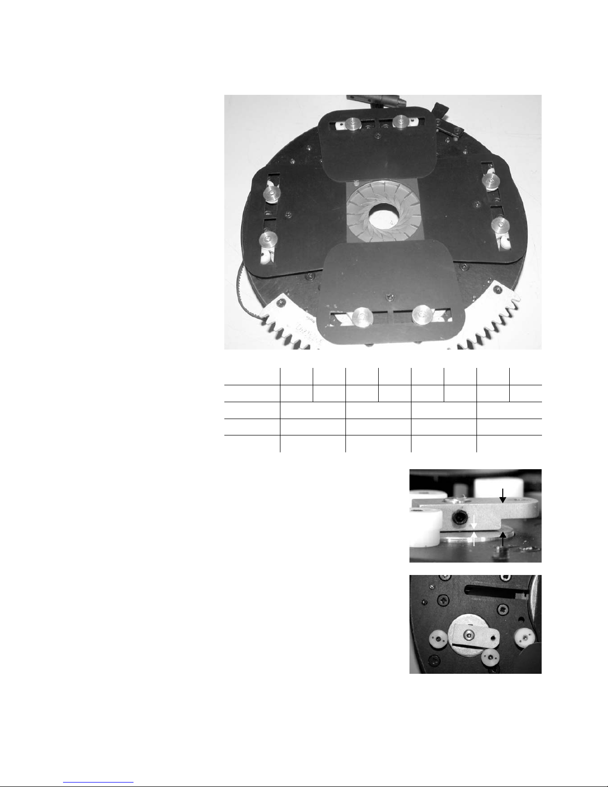
REMOVE FRAMING/IRIS/GOBO MODULE
1 Remove top head shell and lock the head horizontally.
2 Remove fastening screws as shown on each side.
3 Unplug the fan wires, framing/iris/gobo wires, dimmer cable (16), CMYC wires, and the
CMYC thermosensor (T) as shown.
4 Carefully lift the module out by the bridges.
1
2
2
2
33
4
4
5
6
7
1. fan connectors
2. framing/iris/gobo connectors
3. module bridges
4. fastening screws
5. dimmer connector
6. CMYC connectors
7. CMYC thermosensor connector
Page 5
Module disassembly 5
© 2000 Martin Professional A/S, Denmark
MAC 2000 Performance Service Manual
MODULE DISASSEMBLY
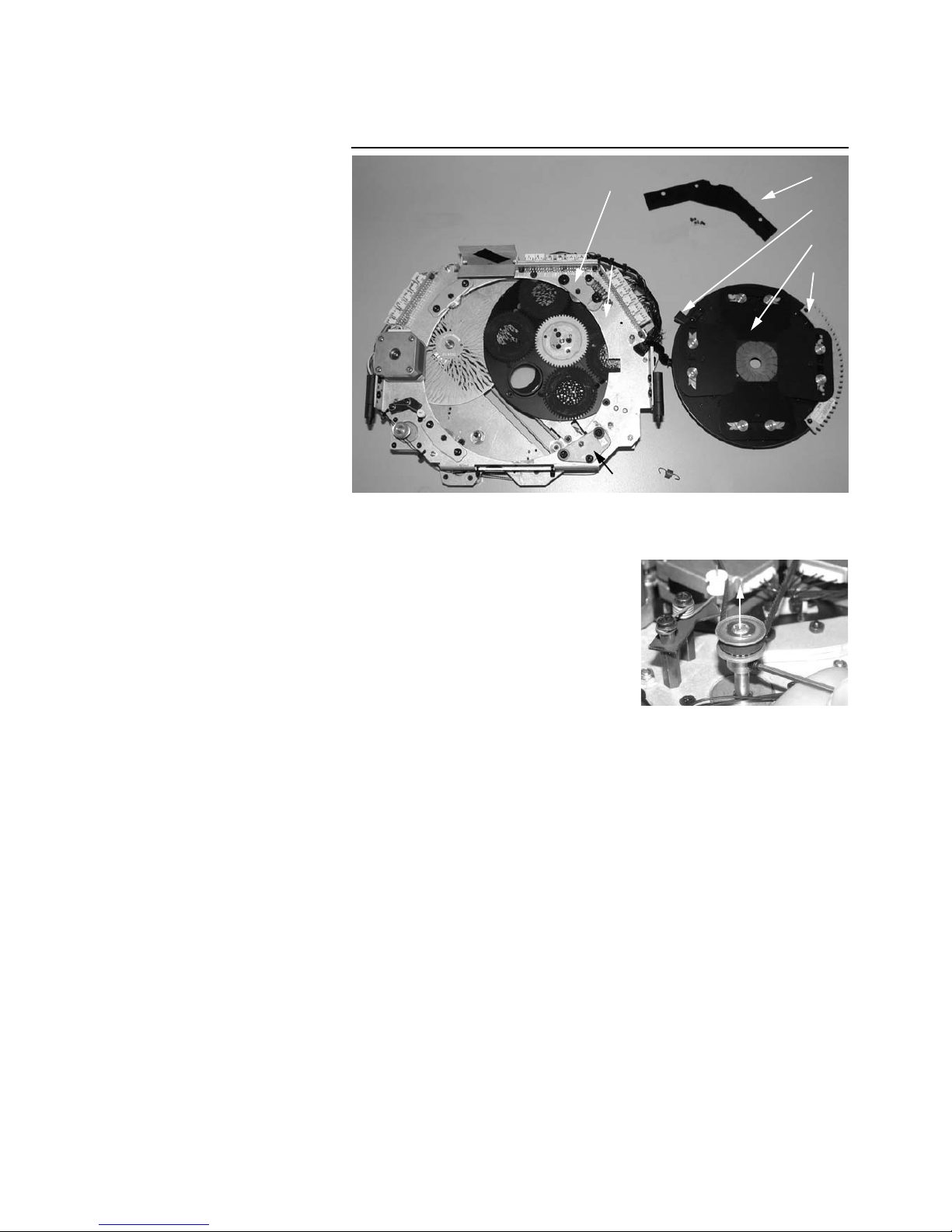
SEPARATE THE FRAMING/IRIS MODULE
1 To avoid damaging the iris belt when removing
and replacing, remove the iris motor gear from
the motor shaft.
2 Remove the cable guard.
3 Align the framing rotation stop with the access
hole in the framing plate.
4 Pull the springed guide wheel levers back to
release the module, you can remove springs to
make this easier, and lift out the rotating assembly.
5 Installation is the reverse. Important note:
Avoid twisting the cable bundle when
replacing the rotating assembly
.
1. cable guard
2. framing rotation stop
3. framing wheel and iris
4. framing wheel rack
5. guide-wheel levers
6. framing plate
7. gobo module
1
2
4
6
5
3
5
Page 6
Module disassembly 6
© 2000 Martin Professional A/S, Denmark
MAC 2000 Performance Service Manual
SEPARATE GOBO MODULE FROM FRAMING/IRIS
MODULE
1 Remove 5 torx screws from the module spacers. Do not remove the torx screws that
fasten the gobo rotation sensor PCB.
2 Unplug the gobo wheel sensor (29) and the gobo rotation sensor (28). Unplug the
gobo motors (1 and 2) from the connection print. Cut the strip tie securing the gobo
animation wheel motor and sensor.
3 Unfold the module.
1.gobo module
2. framing/iris module
1 2
Page 7
Framing shutters 7
© 2000 Martin Professional A/S, Denmark
MAC 2000 Performance Service Manual
FRAMING SHUTTERS
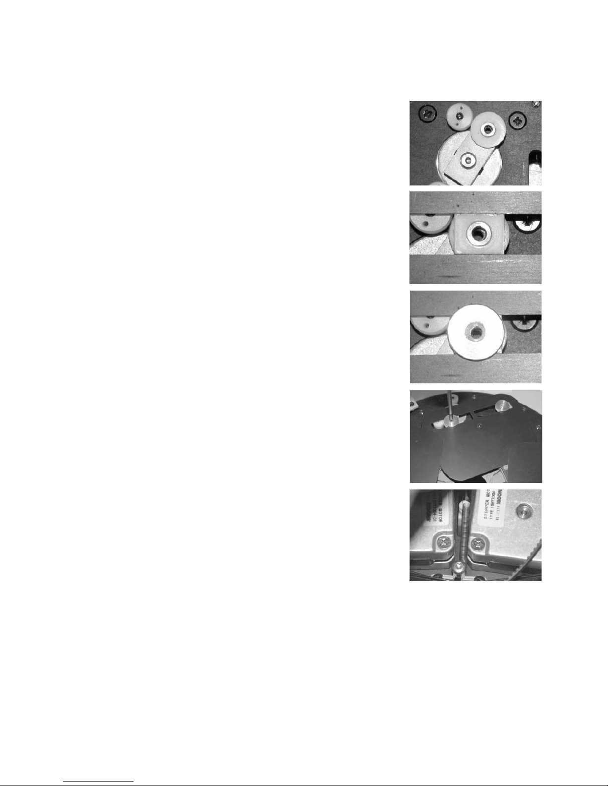
REPLACE MOTOR
The Pozidrive motor screws are locked
with threadlock and can be difficult to
remove without stripping the head.Use
a PZ 0 screwdriver in excellent condi-
tion. Heating the screws well with a
soldering iron softens the threadlock
and makes removal easier.
1 Separate the framing/iris module.
2 Remove the brass discs and lift off the shutter blade. There is a small spring on the
back.
3 Remove the motor screws from the shutter side of the plate. Remove the motor.
4 Remove shutter arm from shaft.
5 Install the new motor and loosely place the shutter arm on the shaft, between the
stops.
1
2
3
4
5
6
1. shutter blade
2. brass discs
3. nylon slide assemblies
4. outside stop
5. shutter arm
6. inside stop
Page 8
Framing shutters 8
© 2000 Martin Professional A/S, Denmark
MAC 2000 Performance Service Manual
ADJUST MOTOR
1 Set the shutter arm’s position along the shaft
to distance “A” (using a feeler gauge) or
distance “B” (using a calliper gauge) and
tighten one of the set screws just enough to
hold the adjustment.
2 Plug an extension cable between the
connection PCB and the head cable or PCB
output.
3 Apply power and cancel the pan/tilt reset by
pressing the “Menu” and “Enter” keys on the
control panel. Allow the reset to complete and
then navigate the control menu to UTIL / AdJ /
HEAd / bEAM / AdJ. Press the drive lever
against the inside stop and tighten the set
screws.
4 Check the adjustment with the “IN” and “OUT”
commands: when selected, the drive arm
should be about 0.5 mm (0.02 in.) from the
inside and outside stops, respectively. (If the motor turns backwards, the extension
cable is reversed at one end.)
Motor LA LB TA TB RA RB BA BB
Socket/Wire 345678910
Blade position upper lower upper lower
Distance “A” 1.2 mm 0.15 - 0.2 mm 1.2 mm 0.15 - 0.2 mm
Distance “B” 6.2 mm 5.15 - 5.2 mm 6.2 mm 5.15 - 5.2 mm
RBRA
BB
BA
LALB
TB
TA
A
B
Page 9
Framing shutters 9
© 2000 Martin Professional A/S, Denmark
MAC 2000 Performance Service Manual
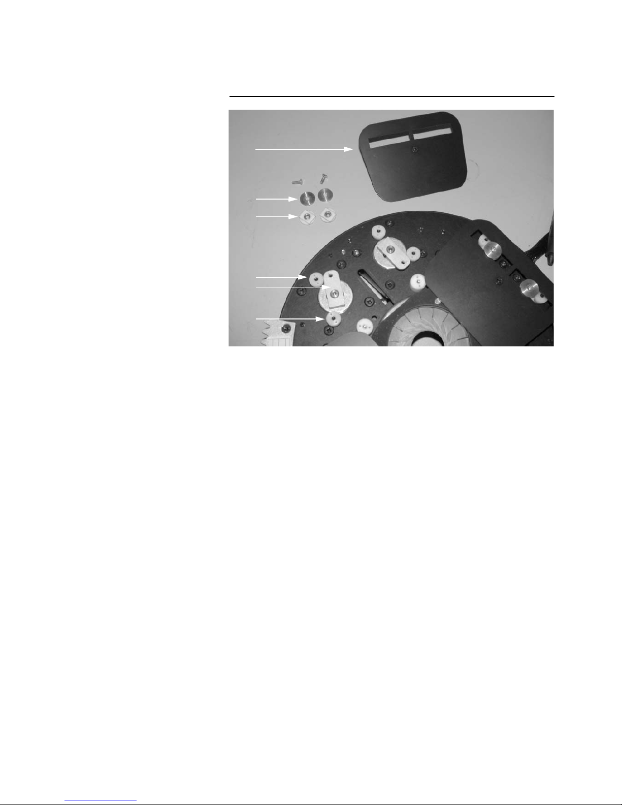
REPLACE SHUTTER BLADE
1 Remove the rectangular guide from each
sliding nylon assembly. Place the sliding
assembly on the shutter arm.
2 Position the shutter blade over the sliding
assemblies.
3 Press the rectangular guides into the slots and
onto the brass sleeves.
4 Place the brass discs over the rectangular
slides with the countersink up.
5 Align everything and insert the screws.
Tighten securely.
6 Flip the wheel over and hook the spring onto
the shutter blade pin.
Page 10
Framing rotation 10
© 2000 Martin Professional A/S, Denmark
MAC 2000 Performance Service Manual
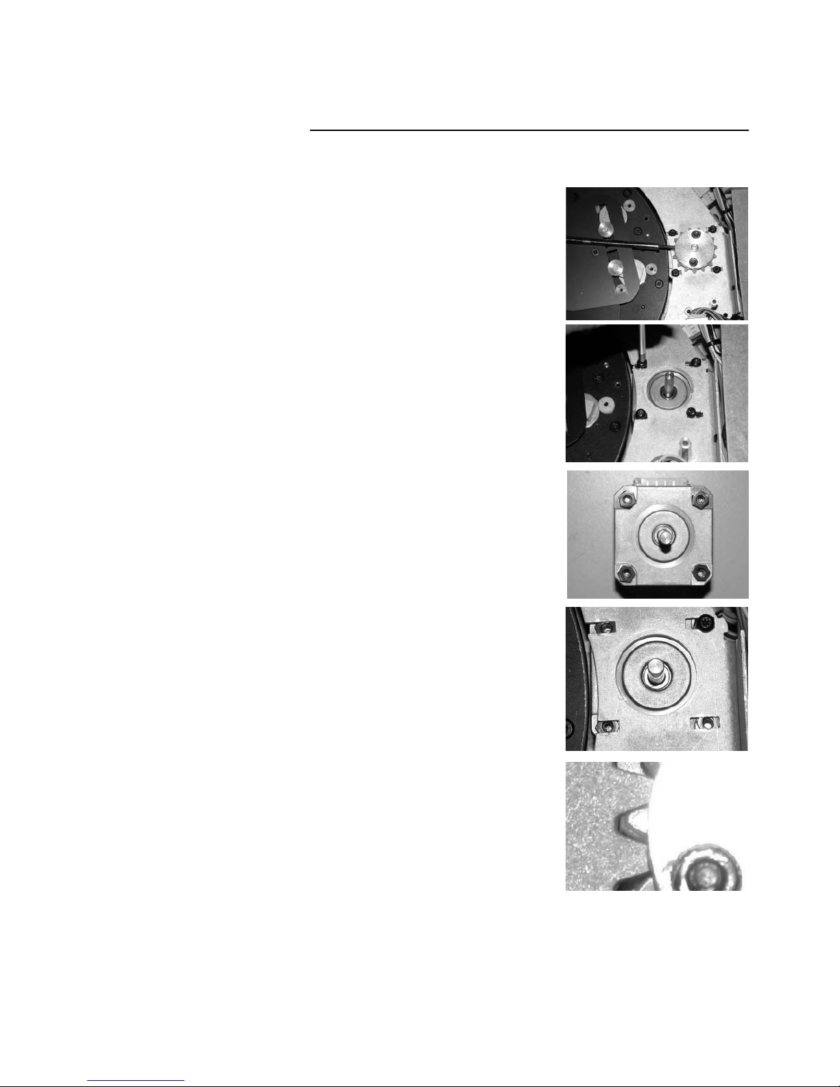
FRAMING ROTATION
REPLACE MOTOR OR GEAR
1 Separate the gobo module from the
framing/iris module.
2 Remove the rack from the framing wheel as
shown here or separate the framing/iris
module. Loosen 2 set screws and pull the gear
assembly off the motor shaft.
3 Remove and unplug the motor.
4 Arrange the nuts on the new motor and turn it
so the socket faces away from you. Note that
the nuts between the motor and the plate are
oversized and used as spacers only.
5 Place the module over the motor as shown and
replace the screws loosely.
6 Put the gear assembly on the motor shaft but
do not tighten. Put the framing wheel back in
the framing module, or, replace the rack using
new M3 x 12 CS Torx screws (P/N 08050801) to
replace the taptites.
7 Position the frame rotation motor so that there
is a paper-thin gap and the slightest amount of
play between the motor gear and the rack.
Tighten the motor screws and verify that the
framing wheel turns smoothly with even
resistance through its range.
8 Center the motor gear on the rack and tighten
both set screws.
9 Plug in the new motor and reassemble the
module.
ADJUSTMENT
Frame rotation is electrically indexed: no mechanical adjustment is required.
Page 11

Iris 11
© 2000 Martin Professional A/S, Denmark
MAC 2000 Performance Service Manual
IRIS
REPLACE IRIS
1 Separate the framing/iris module and place
the wheel with the shutter blades up.
Remove the bottom and right shutter
blades and partially remove the top blade to
access the 3 iris screws.
2 Remove 3 screws from iris.
3 Turn the wheel over and remove 4 screws
from iris drive plate. Lift out the iris.
4 Insert the new iris with the drive lever at 1
o’clock as shown. Turn the module over,
align the holes, and fasten the iris with the 3
screws.
Page 12

Iris 12
© 2000 Martin Professional A/S, Denmark
MAC 2000 Performance Service Manual
5 Turn the module back over to replace the
iris drive pulley. Orient the plate with the
spring end up, towards the wire bundle, and
turn the drive pulley to align the slot with
the iris lever. Align the plate over the spacer
nuts and fasten. Tighten the screws on the
side with the spring after tightening the
other 2 screws.
6 Replace the shutter blades.
REPLACE IRIS BELT
1 Work the iris belt off the drive motor.
2 Remove the belt retaining screw from the iris drive pulley and pull off the old belt.
3 Apply a few drops of
Loctite 408
to the drive pulley, under the retaining screw, place
the belt on the drive pulley, and replace the retaining screw.
4 Work the belt onto the motor gear and tensioner.
ADJUST IRIS
No mechanical adjustment of the iris is required. The iris can be calibrated with a software
offset value.
Page 13

Gobo animation wheel 13
© 2000 Martin Professional A/S, Denmark
MAC 2000 Performance Service Manual
GOBO ANIMATION WHEEL
REPLACE POSITION BELT
1 Remove the gobo animation wheel.
2 Release belt tension and work the position
belt off the end pulley closest to the motor.
Remove the 2 guide rail retaining brackets.
Snap the guide rails out of the plastic clips.
3 Work the belts off the pulleys.
4 Remove the sliding assembly from the
guide rails and loosen the belt clamp.
Remove the old belt and install the new one
with the teeth facing the clamp. Tighten the
clamp.
5 Put the sliding assembly in its approximate
location to remove twist. Lead the belt
down through the motor hole and up over
the gear.
6 Snap the inside guide rail into the clip, then
work the belt over the tensioner and end
pulleys.
1. rotation belt
2. rotation belt tensioner
3. gobo animation wheel
4. sliding assembly
5. guide rail retaining bracket
6. inside guide rail
7. position belt tensioner
8. position motor
9. rotation motor
10. outside guide rail
11. position belt
1
2
4
5
6
3
7
8
9
10
11
Page 14
Gobo animation wheel 14
© 2000 Martin Professional A/S, Denmark
MAC 2000 Performance Service Manual
7 Insert the outside guide rail into the sliding
assembly. Snap the outside rail into place.
8 Replace the guide rail retaining brackets.
9 Work the rotation belt over the rotation
motor and tensioner.
10 Replace the gobo animation wheel.
REPLACE POSITION
MOTOR
1 Separate the gobo module from the
framing/iris module to access the inside
motor screw. Unplug and remove motor.
2 Move motor gear to new motor. Install new
motor with plug socket towards the belt
tensioner.
3 Align the motor gear with the belt pulleys
and tighten the set screw.
ADJUSTMENT
The wheel position is electrically indexed: no mechanical adjustment is required.
REPLACE ROTATION BELT
1 Remove the gobo animation wheel.
2 Release tension from the belt and work it
off. This is easier if you separate the
framing/iris module, but it is not necessary
to do so.
Page 15

Gobo animation wheel 15
© 2000 Martin Professional A/S, Denmark
MAC 2000 Performance Service Manual
3 Lead the new belt around the drive gear and
under the guide rollers. Then lead the belt
around the motor gear and tensioner.
4 Replace the gobo animation wheel.
REPLACE ROTATION
MOTOR
1 Separate the gobo module from the
framing/iris module to access the motor
screws. Remove the gobo animation wheel.
2 Remove the 3 motor screws and remove the
motor.
3 Cut strip ties as required and unplug the
motor (13).
4 Move the gear to the new motor. Position it
with 1.5 - 1.6 mm (1/16 in.) between the face
of the motor and the bottom of the adapter.
Tighten the set screw.
If you don’t have 4 hands, hold 2 of the
screws in place with tape while you
start the third screw.
5 Place the new motor with the cable over the
sensor as shown and fasten with screws
and stand-offs.
6 Plug in the motor and arrange the belt.
7 Assemble the module, replace the gobo
animation wheel, and tie the cable with new
strip ties.
8 Verify that the sensor magnet aligns
vertically with the Hall sensor.
ADJUSTMENT
The rotation angle is magnetically indexed
using a routine that does not require
mechanical adjustment of the sensor magnet.
Page 16

Gobo wheel 16
© 2000 Martin Professional A/S, Denmark
MAC 2000 Performance Service Manual
GOBO WHEEL
REPLACE ROTATION MOTOR, ROTATION GEAR,
AND BELT
1 Separate the gobo module from the
framing/iris module.
2 Unscrew and remove the silicone gear.
To access the inner screw, remove the
gobo holder from position 1, which is
between open and the magnet. To
access the outer screws, align the service notch in the wheel with the screw.
3 Take the gobo holder out of position 1 and
remove tension from the belt by loosening
the motor screws.
4 Remove the snap ring from the bearing and
remove the gobo wheel. The belt can now
be replaced.
5 Remove the motor. When installing a new
motor, we recommend a new bearing (P/N
16900110, “Bearing/motor adaptor,
MAC2000” and shaft adaptor (P/N
16300220, “Gear wheel adaptor, MAC2000.”
If reusing the existing hardware, be careful
not to damage the bearing: it must fit
precisely inside the gobo wheel.
6 Place the bearing on the new motor. Apply
threadlock to the set screws and then press
the shaft adapter onto the motor shaft with
a 1.15 mm feeler gauge between the adapter
and the bearing. Tighten the set screws.
Page 17
Gobo wheel 17
© 2000 Martin Professional A/S, Denmark
MAC 2000 Performance Service Manual
7 Arrange the motor spacer as shown.
8 Place the motor as shown and fasten.
9 Place the belt over the motor and then
press the gobo wheel onto the bearing.
Replace the snap ring. Work the belt over
the wheel rotation motor.
10 To make it easier to adjust later, align the
magnet on the gobo wheel with the sensor
and, while holding the gobo wheel, turn the
motor adaptor so the set screw points
outward. Pull back on the motor to tighten
the belt and then tighten the motor screws.
11 Replace the gobo holder.
12 Replace the silicone gobo rotation gear
with three new M3 x 4 mm countersunk
screws.
13 Reassemble and install the module.
REPLACE GOBO WHEEL
MOTOR
1 Separate the gobo module from the
framing/iris module.
2 Remove the 3 screws and remove the gobo
wheel motor.
Page 18

Gobo wheel 18
© 2000 Martin Professional A/S, Denmark
MAC 2000 Performance Service Manual
3 Transfer the cable, stand-off nuts, and gear
to the new motor. Position the gear 0.8 mm
from the motor. Tighten the set screw.
4 Position the motor with its plug facing the
gobo rotation motor and fasten loosely.
5 Work the belt over the gear.
6 To make it easier to adjust the gobo wheel
later, turn the gobo wheel to align the
magnet with the sensor and turn the motor
adaptor so the set screw points outward.
7 Pull back on the motor to tighten the belt
and then tighten the motor screws.
8 Start a new strip tie for the motor cables
through the module plate before
reassembling the module.
ADJUSTMENT
1 Apply power to the fixture and wait until it
has finished resetting.
2 Via the menu, select motor adjustment
position UTIL/AdJ/HEAd/GObO/AdJ.
Press Enter.
3 Turn the gobo wheel until the magnet is centered over the magnetic sensor. Tighten
the set screw.
4 Reset the fixture and verify that it resets correctly. Re-select
UTIL/Adj/HEAd/GOb 1/ADj and verify that the magnet is positioned right at the
sensor. Check the alignment optically and calibrate the gobo wheel position if
necessary.
Page 19

Module removal and installation 19
© 2000 Martin Professional A/S, Denmark
MAC 2000 Performance Service Manual
ZOOM / FOCUS MODULE
MODULE REMOVAL AND INSTALLATION
REMOVE ZOOM / FOCUS MODULE
1 Remove the following:
• top and bottom head covers
• front lens ring
• framing/iris/gobo module (p. 4)
2 Remove the front lens now if you are
going to replace a lens, belt, or motor.
3 At the bottom of the head, remove the
front screw from the module alignment
plates and push the plates to the side.
4 Disconnect the 2-pole cable labelled
“23” from the right side connection
block.
Page 20

Module removal and installation 20
© 2000 Martin Professional A/S, Denmark
MAC 2000 Performance Service Manual
INSTALL ZOOM / FOCUS MODULE
5 Remove the 4 module fastening
screws.
6 Remove the screws that fasten the
starter to the module. You may need to
lift the module some to access the
bottom screw. Move the starter out of
the way.
7 Lift the module out of the head. Take
care not to damage the frost glass.
1 Find the 2-wire cable labelled “23” and
hold it outside the head.
2 Move the starter to the side and insert
the zoom/focus module into the head.
3 Fasten the starter to the module plate
with 2 M4 x 6 mm metric screws (Martin
P/N 08070401). You need a long
screwdriver to reach to bottom screw.
4 Fasten the zoom / focus module to the
chassis.
Page 21

Module removal and installation 21
© 2000 Martin Professional A/S, Denmark
MAC 2000 Performance Service Manual
5 Reposition and fasten the module
alignment plates at the bottom of the
head.
6 Insert the framing module and fasten it.
7 Connect the top fan cable to the 2 pins
closest to the starter on the junction
print labelled “38”. (The left-side lamp
cooling fan connects to the other 2
pins.)
8 Connect the cable from the bottom fan
to the forward 2 pins of socket 37.
Connect cable “23” to socket “D”.
Connect the zoom/focus microswitch
cable to the rear 3 pins of the center
socket of junction print “31”.
9 Connect and secure all cables in the
left and right wire bundles.
10 Locate the 3-wire cable for the effect
wheel sensor, lead it around the top
fan, and connect it to the sensor PCB.
11 Secure the cables with cable ties at the
corners of the fan.
Page 22

Module removal and installation 22
© 2000 Martin Professional A/S, Denmark
MAC 2000 Performance Service Manual
12 Tuck the right-side wire bundle into the
slot in the zoom/focus module plate.
13 Install the covers and lens ring.
Page 23

Zoom and focus 23
© 2000 Martin Professional A/S, Denmark
MAC 2000 Performance Service Manual
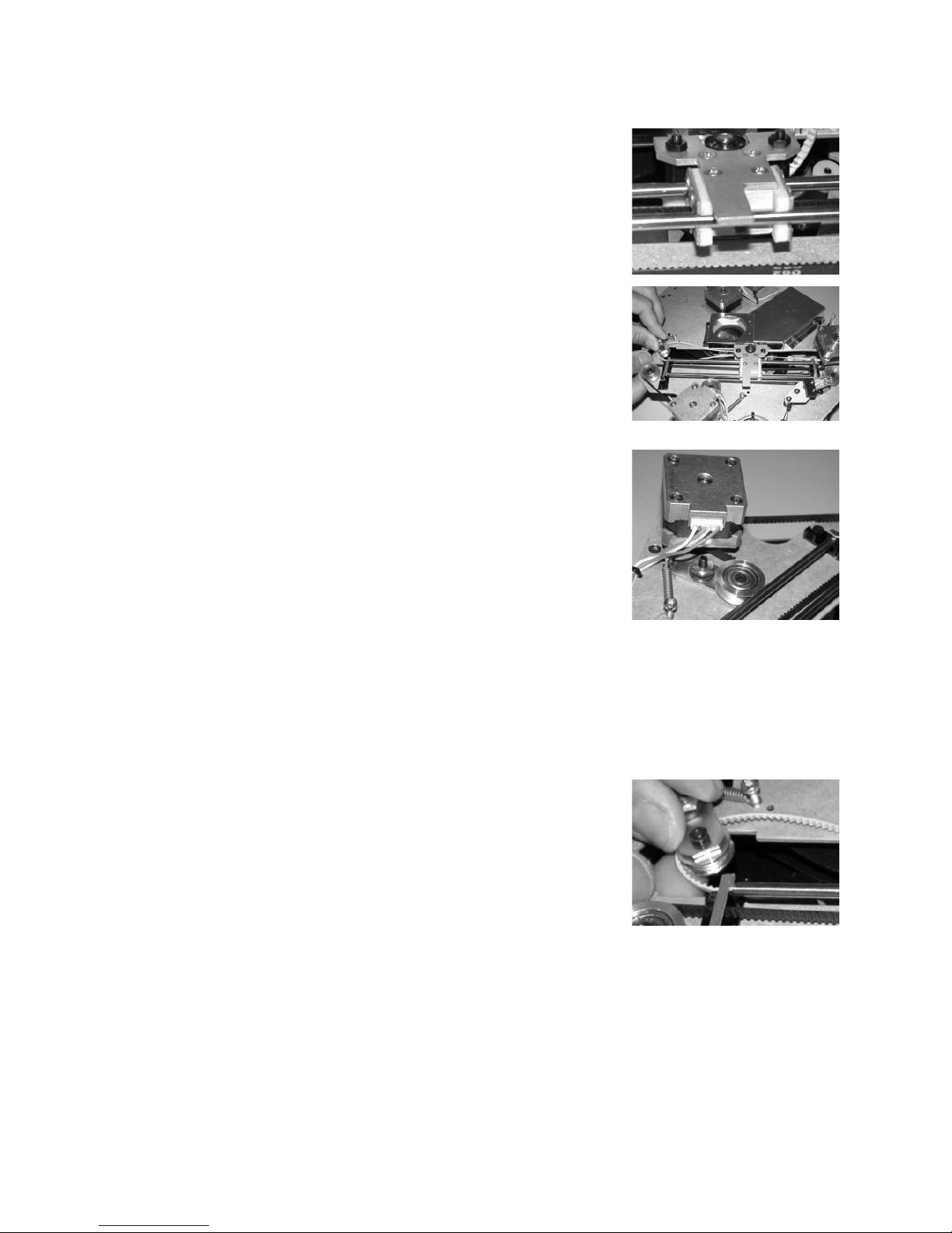
ZOOM AND FOCUS
REPLACE MOTORS
1 Remove the following:
• framing module (p. 4)
• front lens ring
• front lens
• zoom / focus module (p. 19)
• effect wheel module (p. 31)
2 Unplug and free the wires for the top
and bottom fans. Unscrew and remove
both fans.
3 Unplug the focus reset switch wires
and the focus motor.
4 Unplug the zoom motor.
5 Measure the length of the zoom and
focus belt tails at the rear plate.
Unscrew the clamps on the rear plate
and release the belts.
6 Pry the shaft retaining rings off of the
back end of the focus and zoom rails.
7 Remove 8 screws fastening the rear
plate to the side plates.
8 Remove 2 screws fastening the right
side plate to the front plate. Pull the
rear plate off the zoom/focus rails.
Page 24

Zoom and focus 24
© 2000 Martin Professional A/S, Denmark
MAC 2000 Performance Service Manual
9 Remove the focus assembly. Install a
new motor as shown and transfer the
gear. Do not tighten the set screw.
10 Remove the zoom assembly. Remove
the larger plastic slide. Install a new
motor as shown and transfer the gear.
Do not tighten the set screw. Reinstall
the plastic slide.
11 Place the zoom assembly on the zoom
rails.
12 Place the focus assembly on the focus
rails.
13 Thread the focus belt over the rollers
and gear.
14 Install the rear and right-side plate.
Fasten with metric hardware (P/N
08070801, “M4x8 screw, Torx, cs,
black”) instead of the original taptites.
Use an M4 nut to secure the screw if
the threads are stripped.
Page 25

Zoom and focus 25
© 2000 Martin Professional A/S, Denmark
MAC 2000 Performance Service Manual
15 Push or pull the zoom and focus rails
through the rear plate. The end of the
rail shall not stick out more than 7 mm
from the back of the rear plate. Fasten
with 4 new Starlock 5 mm shaft
retaining rings, P/N 08230113.
16 Arrange and fasten the focus belt.
• Slip the belt off of the tension
spring.
• Verify that the belt runs correctly
over the guide rollers and gear.
• Feed the belt through the slot in the
rear plate and under the clamp.
• Clamp the belt with the same length
of loose tail as measured earlier, or
use trial and error to achieve proper
tension.
• Guide the belt over the tension
spring.
17 Align the focus motor gear with the belt
and tighten the set screw.
18 Similarly arrange and fasten the zoom
belt.
19 Insert the focus reset switch and motor
wires through the slot between the
right-side plate and the bottom plate.
Connect the wires.
20 Install the fans.
21 Plug in the zoom motor cable. Connect
the bottom fan cable to the forward 2
pins of socket 37 on the right-side
junction print.
Page 26

Zoom and focus 26
© 2000 Martin Professional A/S, Denmark
MAC 2000 Performance Service Manual
REPLACE BELTS
22 Secure the wires at the bottom of the
module with 3 cable ties at the corners
of the fan.
23 Connect the top fan cable to the to the
2 pins closest to the starter on the
junction print labelled “38”.
24 Connect the zoom/focus microswitch
cable to the rear 3 pins of the center
socket of the right-side junction print
labelled “31”.
25 Install the effect wheel module (p. 31).
Verify that the wheel turns freely and
adjust the position of the rails if
necessary.
26 Install the zoom/focus module (p. 20).
1 If replacing the focus belt, remove
• the top head cover
• front lens ring
• front lens
• framing module (p. 4)
•top fan
2 If replacing the zoom belt, remove the
• top and bottom head covers
• front lens ring
• framing module (p. 4)
• one of the effect wheel effects
Page 27

Zoom and focus 27
© 2000 Martin Professional A/S, Denmark
MAC 2000 Performance Service Manual
REPLACE ZOOM LENS
3 Loosen the belt clamps at each end and
remove the belt. (The focus belt is
shown here; the zoom belt procedure is
identical).
4 Position the replacement belt under the
clamp and tension spring with
• the belt’s teeth facing down
• the belt centered under the spring
• the spring square with the clamp
• the end of the belt and spring flush
with the edge of the clamp.
5 Tighten the front clamp.
6 Working from front to back, thread the
belt over the rollers and motor gear.
Feed the belt through the slot in the
rear plate and under the clamp.
7 With the belt on the spring and with the
spring compressed by about half, pull
the belt from the back and note the
length of the tail. Then take the belt off
the spring and clamp the belt at the
back. Finally, place the belt back on the
spring.
8 Reassemble everything.
1 Remove the front lens ring and lens.
2 Unscrew and remove the zoom lens.
Discard the original taptite screws.
3 Install the replacement lens assembly
with the flat sides of the bracket down
and to the left (as you face the head).
Fasten with new M3 x 8 mm metric
screws, P/N 08050703, “M3x8 screw,
Torx, ph, black”.
Page 28

Zoom and focus 28
© 2000 Martin Professional A/S, Denmark
MAC 2000 Performance Service Manual
REPLACE FOCUS LENS
1 Remove the following parts:
• top cover
• front lens ring
• front lens
• zoom lens (p. 27)
•top fan
• one of the effect wheel effects
2 Pry the starlock shaft retaining ring off
of the rear end of the upper zoom rail.
3 Pull the rail forward to provide
clearance for the lens. You do not have
to remove it fully.
4 Unscrew the focus lens from the
bracket. Discard the original screws.
5 Work the lens out through the top fan
opening. Insert the new lens with the
longest end of the barrel facing
forwards. Fasten the lens with 4 new
M3 x 8 mm metric screws, P/N
08050703, “M3x8 screw, Torx, ph,
black”.
6 Push the zoom rail back into place and
fasten with a new Starlock 5 mm shaft
retaining ring, P/N 08230113. The rail
may not stick out more than 7 mm past
the rear plate.
7 Insert the effect and verify that the
effect wheel turns freely.
8 Install the zoom lens (p. 27).
9 Reassemble the remaining parts.
Page 29

Zoom and focus 29
© 2000 Martin Professional A/S, Denmark
MAC 2000 Performance Service Manual
ADJUST ZOOM RESET SWITCH ACTIVATOR
Perform this procedure if the fixture reports a zoom error (ZOER) after resetting or if you
replace the entire zoom module.
ADJUST FOCUS RESET SWITCH ACTIVATOR
Perform this procedure if the fixture reports a focus error (FOER) after resetting or if you
replace the entire focus module. It is easiest to perform while the zoom / focus module is
removed from the head.
1 Remove the following:
• top cover
• front lens ring
• front lens
2 Back the set screw that activates the
zoom reset micro-switch out a few
turns.
3 With the power off, slide the zoom lens
all the way forward and hold it in this
position.
4 Turn the set screw clockwise until you
hear the micro-switch click. Turn the
screw another half to a whole turn
clockwise.
5 Reinstall the lens and covers.
1 Remove the framing module (p. 4).
2 Back the set screw on the rear plate of
the zoom / focus module out a few
turns.
3 With the power off, slide the focus lens
all the way to the back and hold it there.
4 Turn the set-screw clockwise until you
hear the micro-switch click. Turn the
screw another whole turn clockwise.
5 Reassemble.
Page 30

Zoom and focus 30
© 2000 Martin Professional A/S, Denmark
MAC 2000 Performance Service Manual
REPLACE EFFECT FAN
1 Remove the top or bottom head cover,
depending on the fan to be replaced.
2 Unplug and free the fan wires.
3 Unscrew and remove the old fan. Install
the new fan and plug it in.
4 Tie the wires with new cable ties. Use
P/N 13104000, “Strap, black, high temp,
2.5x98mm”.
5 Apply power and check fan operation
before replacing the cover.
Page 31

Effect wheel 31
© 2000 Martin Professional A/S, Denmark
MAC 2000 Performance Service Manual
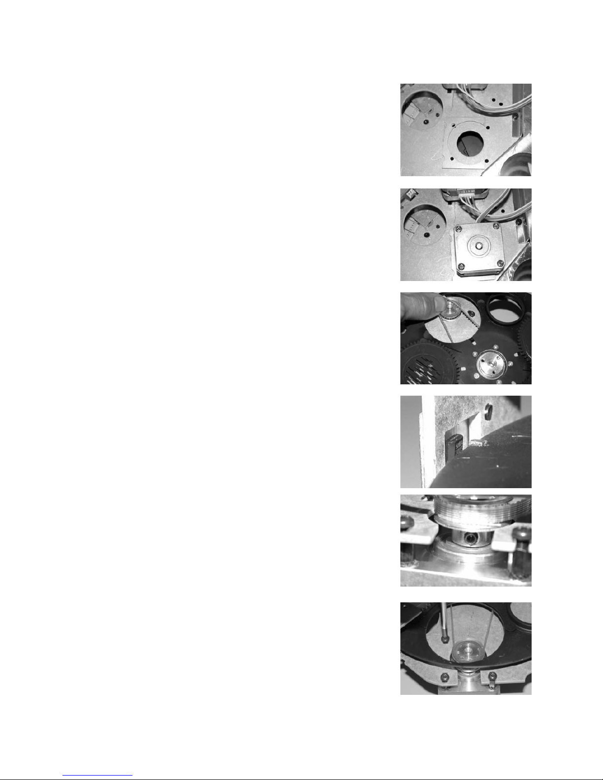
EFFECT WHEEL
REMOVE EFFECT WHEEL MODULE
INSTALL EFFECT WHEEL MODULE
REPLACE EFFECT WHEEL MOTOR
1 Remove the framing module (p. 4).
2 Remove one of the effects from the
effect wheel.
3 Using a short screwdriver or
equivalent, remove the 4 screws that
fasten the effect wheel module to the
zoom / focus module.
4 Unplug the effect wheel motor as you
remove the module.
1 Plug in the effect wheel motor. Turn the
motor so that the socket points down
and insert the motor through the rear
plate of the zoom / focus module. The
triangular corner of the module plate
points towards the junction print.
2 Align the screw holes and fasten with
P/N 08070801, “M4x8 screw, Torx, cs,
black”, instead of the original taptites.
3 Install the effect in the effect wheel.
4 Install the framing module.
1 Remove the effect wheel module.
2 Loosen the set screws and pull the
effect wheel off of the motor shaft.
3 Unscrew the old motor from the plate.
Install a new motor with the plug facing
away from the triangular corner.
4 Place the effect wheel on the motor
shaft. Do not tighten the set screws.
5 Reinstall the module and adjust. (p. 33)
Page 32

Effect wheel 32
© 2000 Martin Professional A/S, Denmark
MAC 2000 Performance Service Manual
REPLACE EFFECT WHEEL
REPLACE VARIABLE FROST FILTER
1 Remove the effect wheel module (p.
31).
2 Unscrew the wheel from the adaptor.
3 Place the replacement effect wheel on
the shaft adaptor and orient it as shown
with respect to the spring and set
screws. Fasten.
4 Reinstall the effect module (p. 31).
5 Transfer the effects to the new wheel. In
the standard configuration, the prism is
located next to the open position and
the wide angle lens is next to full frost.
6 Check the alignment and adjust if
necessary.
1 Remove the effect module.
2 Carefully remove the old filter and cut
away the remaining glue with a sharp
razor blade. Clean the surfaces with
alcohol.
3 Position the filter on the wheel using
the old glue line as your guide and
clamp it in place.
Page 33

Effect wheel 33
© 2000 Martin Professional A/S, Denmark
MAC 2000 Performance Service Manual
ADJUST EFFECT WHEEL
4 Apply a continuous bead of “Silicone
glue, medium temp. (250C), black” (P/N
37001001) along the edge of the glass.
5 Allow the glue to cure for 24 hours
before reinstalling the effect wheel
module. (p. 31)
1 Verify that the rim of the effect wheel
aligns with the sensor IC and that the
effect wheel rotates freely.
2 If the rim and sensor do not align,
check the lateral position of the effect
wheel along the motor axis. There
should be 7.7 mm (0.30 in.) measured
inside-to-inside between the effect
wheel (at the metal) and the plate for
the effect wheel motor. You can also
measure with a feeler gauge between
the face of the motor and the heads of
the screws on the back of the adaptor:
there should be a 0.8 mm gap. The gap
should not be any smaller, but may be a
slightly larger if the wheel clears the
framing module.
3 If the lateral position is correct and the
wheel does not align with the sensor,
the sensor IC may be bent out of
position. Straighten the IC or replace
the sensor PCB.
4 Apply power to the fixture and allow it
to reset.
5 Select UTIL > AdJ > HEAd > EFF > AdJ
from the control panel menu.
Page 34

Effect wheel 34
© 2000 Martin Professional A/S, Denmark
MAC 2000 Performance Service Manual
6 With the set screws loose, center the
magnet on the rim of the effect wheel
with the sensor IC. Tighten one set
screw. Switch off the power and tighten
the second set screw.
7 Reset the fixture and repeat step 5 to
verify the adjustment.
 Loading...