

Page 1
Martin®
Sonic Horns
Go to Martin® Sonic Horns web page
Operator’s Manual
M3829
Page 2
Important
MARTIN ENGINEERING HEREBY DISCLAIMS ANY LIABILITY FOR: DAMAGE DUE TO
CONTAMINATION OF THE MATERIAL; USER’S FAILURE TO INSPECT, MAINTAIN AND TAKE
REASONABLE CARE OF THE EQUIPMENT; INJURIES OR DAMAGE RESULTING FROM USE OR
APPLICATION OF THIS PRODUCT CONTRARY TO INSTRUCTIONS AND SPECIFICATIONS
CONTAINED HEREIN. MARTIN ENGINEERING’S LIABILITY SHALL BE LIMITED TO REPAIR
OR REPLACEMENT OF EQUIPMENT SHOWN TO BE DEFECTIVE.
Observe all safety rules given herein along with owner and Government standards and regulations. Know
and understand lockout/tagout procedures as defined by American National Standards Institute (ANSI)
z244.1-1982, American National Standard for Personnel Protection - Lockout/Tagout of Energy Sources -
Minimum Safety Requirements and Occupational Safety and Health Administration (OSHA) Federal
Register, Part IV, 29 CFR Part 1910, Control of Hazardous Energy Source (Lockout/Tagout); Final Rule.
The following symbols may be used in this manual:
!
DANGER
Danger: Immediate hazards that will result in severe personal injury or death.
!
WARNING
Warning: Hazards or unsafe practices that could result in personal injury.
!
CAUTION
Caution: Hazards or unsafe practices that could result in product or property damages.
IMPORTANT
Important: Instructions that must be followed to ensure proper installation/operation of equipment.
NOTE
Note: General statements to assist the reader.
Page 3

Table of Contents
Section Page
List of Figures . . . . . . . . . . . . . . . . . . . . . . . . . . . . . . . . . . . . . . . . . . . . . . . . . . . . . . . . . . . . . . ii
Introduction . . . . . . . . . . . . . . . . . . . . . . . . . . . . . . . . . . . . . . . . . . . . . . . . . . . . . . . . . . . . . . . . 1
General . . . . . . . . . . . . . . . . . . . . . . . . . . . . . . . . . . . . . . . . . . . . . . . . . . . . . . . . . . . . . . . . 1
Required accessories . . . . . . . . . . . . . . . . . . . . . . . . . . . . . . . . . . . . . . . . . . . . . . . . . . . . . 1
References . . . . . . . . . . . . . . . . . . . . . . . . . . . . . . . . . . . . . . . . . . . . . . . . . . . . . . . . . . . . . 1
Safety . . . . . . . . . . . . . . . . . . . . . . . . . . . . . . . . . . . . . . . . . . . . . . . . . . . . . . . . . . . . . . . . . 1
Materials required . . . . . . . . . . . . . . . . . . . . . . . . . . . . . . . . . . . . . . . . . . . . . . . . . . . . . . . 1
Before Installing Sonic Horn. . . . . . . . . . . . . . . . . . . . . . . . . . . . . . . . . . . . . . . . . . . . . . . . . . .2
Installing Sonic Horn. . . . . . . . . . . . . . . . . . . . . . . . . . . . . . . . . . . . . . . . . . . . . . . . . . . . . . . . . 3
Installing sonic horn. . . . . . . . . . . . . . . . . . . . . . . . . . . . . . . . . . . . . . . . . . . . . . . . . . . . . . 3
Installing restraining cable. . . . . . . . . . . . . . . . . . . . . . . . . . . . . . . . . . . . . . . . . . . . . . . . . 6
Connecting air supply to sonic horn. . . . . . . . . . . . . . . . . . . . . . . . . . . . . . . . . . . . . . . . . . 7
After Installing Sonic Horn . . . . . . . . . . . . . . . . . . . . . . . . . . . . . . . . . . . . . . . . . . . . . . . . . . . . 9
Maintenance. . . . . . . . . . . . . . . . . . . . . . . . . . . . . . . . . . . . . . . . . . . . . . . . . . . . . . . . . . . . . . . . 10
Every month. . . . . . . . . . . . . . . . . . . . . . . . . . . . . . . . . . . . . . . . . . . . . . . . . . . . . . . . . . . . 10
Troubleshooting. . . . . . . . . . . . . . . . . . . . . . . . . . . . . . . . . . . . . . . . . . . . . . . . . . . . . . . . . . . . . 11
Part Numbers . . . . . . . . . . . . . . . . . . . . . . . . . . . . . . . . . . . . . . . . . . . . . . . . . . . . . . . . . . . . . . . 12
Appendix A.. . . . . . . . . . . . . . . . . . . . . . . . . . . . . . . . . . . . . . . . . . . . . . . . . . . . . . . . . . . . . . . . A-1
Table of Contents
Martin Engineering M3829-08/13 i Martin® Sonic Horns
Page 4

Figure Title Page
1 Flush Mount Installation . . . . . . . . . . . . . . . . . . . . . . . . . . . . . . . . . . . . . . . . 4
2 Mid-Mount Installation . . . . . . . . . . . . . . . . . . . . . . . . . . . . . . . . . . . . . . . . . 5
3 Installing Restraining Cable . . . . . . . . . . . . . . . . . . . . . . . . . . . . . . . . . . . . . 6
4 Plumbing Detail for Normally-Closed Solenoid Valve . . . . . . . . . . . . . . . . . 8
5 Martin
6 Martin
7 Martin
®
75Hz Sonic Horn Assembly, P/N SH075-XXXXXXX . . . . . . . . . 14
®
230Hz Sonic Horn Assembly, P/N SH230-XXXXX . . . . . . . . . . . 16
®
75Hz Mega Horn Assembly, P/N SH075M-XXXXXX . . . . . . . . . 17
List of Figures & Tables
Table Title Page
List of Figures
List of Tables
I Martin® 75Hz Sonic Horn Assembly, P/N SH075-XXXXXXX . . . . . . . . . 15
II Martin
III Martin
®
230Hz Sonic Horn Assembly, P/N SH230-XXXXX . . . . . . . . . . . 16
®
75Hz Mega Horn Assembly, P/N SH075M-XXXXXX . . . . . . . . . 18
Martin Engineering M3829-08/13 ii Martin® Sonic Horns
Page 5

Introduction
General The Martin
generates intense sound waves and introduces vibration into vessels, transfer
chutes, gas ducts, and feed pipes to maintain material or gas flow.
This manual provides instructions for installing sonic horns on steel structures
only. For installations on other structures, call Martin Engineering or a
representative
®
Sonic Horn is a pneumatic bulk material-moving system that
.
Specifications See Appendix A for technical data specific to individual models.
Required
accessories
A sonic horn system requires additional accessories in order to be fully
operational. These accessories, which consist of solenoid valves, filters,
regulators, ball valves, air hoses, mounting plates, etc., can be purchased from
Martin Engineering. These accessories are packaged in kits for convenience
and are ordered separately from the sonic horn assembly. Contact Martin
Engineering or a representative to determine which kits are required for your
specific application.
References The following documents are referenced in this manual:
Introduction
• American National Standards Institute (ANSI) z244.1-1982, American
National Standard for Personnel Protection - Lockout/Tagout of Energy
Sources - Minimum Safety Requirements, American National Standards
Institute, Inc., 1430 Broadway, New York, NY 10018.
• Federal Register, Volume 54, Number 169, Part IV, 29 CFR Part 1910,
Control of Hazardous Energy Source (Lockout/Tagout); Final Rule,
Department of Labor, Occupational Safety and Health Administration
(OSHA), 32nd Floor, Room 3244, 230 South Dearborn Street,
Chicago, IL 60604.
• The National Electrical Code (NEC) Handbook, National Fire Protection
Association, 1 Batterymarch Park, P.O. Box 9101, Quincy MA 02269-9101.
• ICS 1-1988, General Standards for Industrial Control and Systems, and
250-1985, Enclosures for Electrical Equipment (1000 Volts Maximum),
National Electrical Manufacturers Association (NEMA), 2101 L Street
N.W., Washington, D.C. 20037.
Safety All safety rules defined in the above documents, and all owner/employer
safety rules, must be strictly followed when installing and servicing this
equipment.
Materials required Materials other than standard hand tools that are required to complete tasks
are listed where applicable.
Martin Engineering M3829-08/13 1 Martin® Sonic Horns
Page 6
Before Installing Sonic Horn
IMPORTANT
WARNING
!
WARNING
!
Before Installation
The delivery service is responsible for damage occurring in
transit. Martin Engineering CANNOT enter claims for
damages. Contact your transportation agent for more
information.
1. Inspect shipping container for damage. Report damage to delivery service
immediately and fill out delivery service’s claim form. Keep any damaged
goods subject to examination.
2. Remove sonic horn assembly from shipping container.
3. If you purchased accessories from Martin Engineering, they will be
packaged separately. Remove this equipment from its shipping container.
4. Take inventory of the equipment received. If anything is missing, contact
Martin Engineering or representative.
Before installing sonic horn, lock out/tag out any equipment
that is loading or unloading material from the vessel.
5. Turn off and lock out/tag out energy source to accessory equipment
according to ANSI standards (see “References”).
If equipment will be installed in an enclosed area, test gas level
or dust content before using a cutting torch or welding. Using
a cutting torch or welding in an area with gas or dust may
cause an explosion.
6. If using a cutting torch or welding, test atmosphere for gas level or dust
content.
Martin Engineering M3829-08/13 2 Martin® Sonic Horns
Page 7

Installing Sonic Horn
NOTE
NOTE
NOTICE OF LIMITED LIABILITY: Due to possible presence of latent
structural defects in the apparatus of the purchaser, Martin Engineering
shall not be responsible for consequential damage to the purchaser’s
equipment and/or apparatus resulting from the application of a Martin
Product. Martin
by the purchaser or other circumstances beyond the control of Martin
Engineering. Liability is disclaimed for the structural soundness of
apparatus or equipment not supplied by Martin Engineering. Liability
shall be strictly limited to the replacement of the purchased product or
refund of the purchase price. To secure the integrity of the installation,
specify supervision by qualified personnel from Martin Engineering.
Engineering shall not be liable for improper installation
Installation
®
Installing sonic
horn
Sonic horns must be solidly mounted to the vessel and the horn must have
unrestricted flow. A variety of installation methods and mount plate designs
can be used to install sonic horns. This section will describe the installation
using the most common methods. If you are not sure how to install the sonic
horn for optimum performance and convenience, contact Martin Engineering
or a representative.
If you are unsure where to locate sonic horn(s) on your vessel,
contact Martin Engineering or your representative.
1. Mark location for each sonic horn on vessel. Make sure sonic horn is not
positioned where material can flow into horn.
Martin Engineering M3829-08/13 3 Martin® Sonic Horns
Page 8
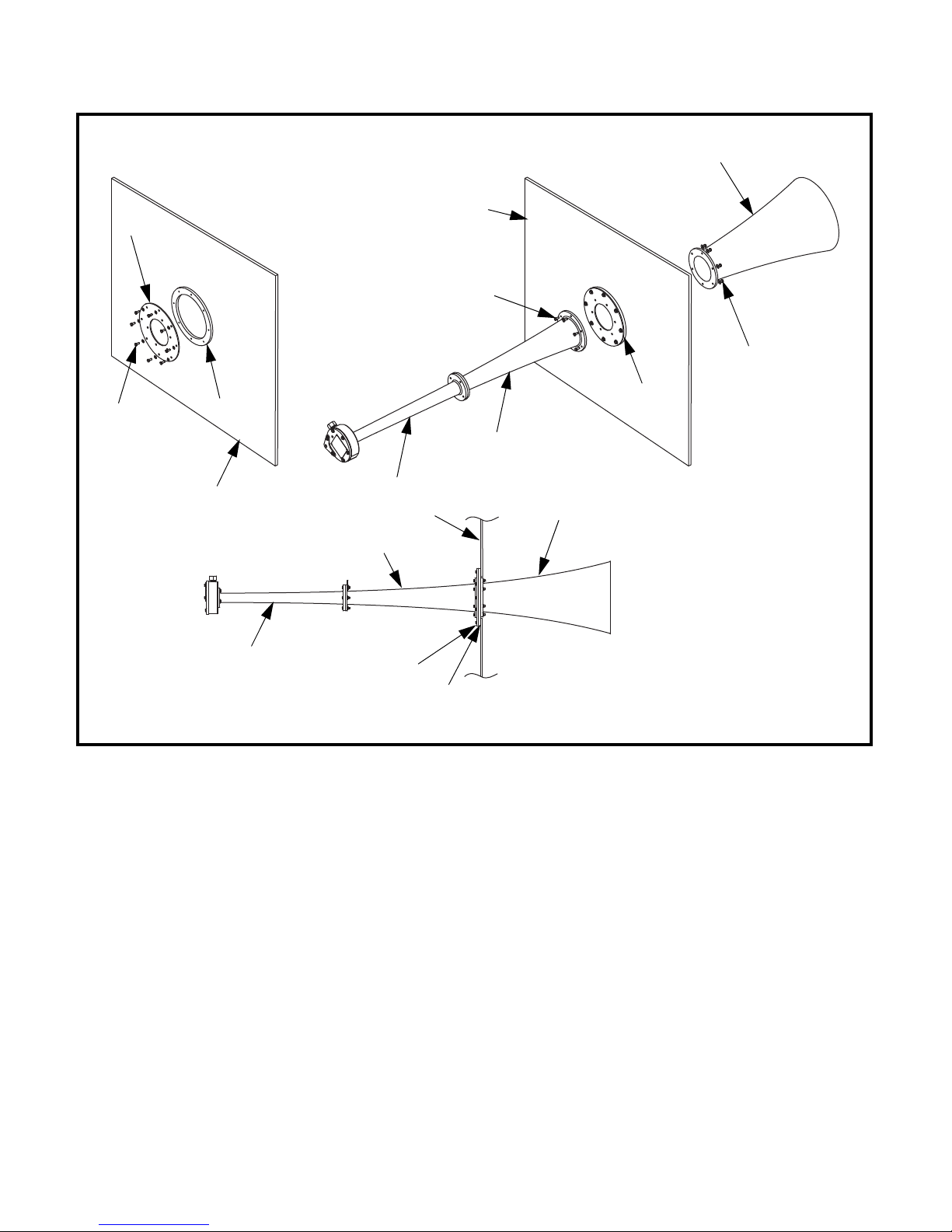
A
C
B
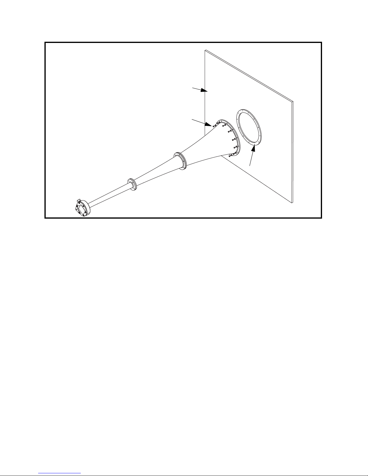
A. Vessel Wall
B. Cap Screw and Washer
C. Flange Ring
Installation
Figure 1. Flush Mount Installation
2. For flush mount installations:
a. Cut a hole in vessel using flange ring (C) as a template.
b. Tack weld flange ring (C) to vessel.
c. Attach sonic horn to flange ring (C) using cap screws and washers (B).
d. Weld flange ring (C) to vessel. Make a continuous weld around
perimeter of flange ring.
Martin Engineering M3829-08/13 4 Martin® Sonic Horns
Page 9
D
F
C
G
E
D
G
I
D
F
G
B
A
A
B
A. Section A
B. Section B
C. Section C
D. Vessel Wall
E. Cap Screw and Washer
F. Fla nge Ri n g
G. Flange Plate
H. Cap Screw
I. Nut and Washer
H
C
Installation
3. For mid-mount installations:
Martin Engineering M3829-08/13 5 Martin® Sonic Horns
Figure 2. Mid-Mount Installation
a. Cut a hole in vessel using flange ring (F) as a template.
b. Tack weld flange ring (F) to vessel.
c. Attach flange plate G) to flange ring (F) using cap screws and
washers (E).
d. Weld flange ring (F) to vessel. Make a continuous weld around
perimeter of flange ring.
e. Place sections A and B of sonic horn on the outside of the flange plate
(G) and place section C on the inside of the flange plate. Attach both
sections to flange plate and to each other using cap screws (H) and
washers and nuts (I).
Page 10

Installing
WARNING
!
A.
B.
C.
D.
D-ring
Vessel Wall
Wire rope
Cable clamp
E. Bracket
D
D
A
B
C
D
E
E
D
restraining cable
Installation
Always install restraining cable to secure sonic horn to vessel.
Without restraining cable, sonic horn could fall and cause
injury.
Do not use restraining cable to mount sonic horn to vessel wall.
Purpose of restraining cable is to keep sonic horn from falling
should it come loose from vessel wall, not as primary means of
securing sonic horn to wall.
1. Weld D-ring (A) onto vessel wall (B) with 1/4-in. (6-mm) field weld.
2. Insert one end of wire rope (C) through D-ring (A) on vessel, making a
Martin Engineering M3829-08/13 6 Martin® Sonic Horns
3. Route wire rope (C) through brackets (E) and back to D-ring on vessel.
4. Insert wire rope (C) through D-ring (A) on vessel, making a 3-in.
5. To fasten each wire loop:
Figure 3. Installing Restraining Cable
3-in. (76-mm) loop.
(76-mm) loop.
a. Clamp wire rope with one cable clamp (D) as close to loop as possible.
Place another cable clamp 1-3/4 in. (44 mm) from first clamp.
b. Leave at least 1 in. (25 mm) of wire rope on dead end.
c. Gradually tighten nuts alternately and evenly to 15 ft-lbs.
Leave 2 to 3 in. (51 to 76 mm) slack in wire rope.
Page 11

Connecting air
IMPORTANT
IMPORTANT
IMPORTANT
WARNING
!
supply to sonic
horn
Depending upon the application, a receiver tank may be
needed to supply amount of air required to effectively operate
sonic horns. For more information contact Martin
Engineering or a representative.
Installation
Do not use a lubricated air supply for sonic horns.
1. Apply pipe sealant to all fittings.
2. See Figure 4. Connect 1” lockout ball valve to compressed air source with
desired length of 1” pipe. Look at arrow on side of ball valve to make sure
flow is correct.
3. Connect air filter/regulator to 1” lockout ball valve with desired length of
1” pipe. Look at arrow on side of air filter/regulator to make sure flow is
correct.
4. Connect 1” to 3/4” reducer to air filter/regulator with desired length of
1” pipe.
5. Connect 3-way electrical solenoid valve to 1” to 3/4” reducer with 6” long
3/4” pipe nipple. See Figure 4 for solenoid connections.
6. Connect 3/4” lockout ball valve to solenoid valve using desired length of
3/4” pipe.
7. Connect sonic horn sound generator to 3/4” lockout ball valve using
braided stainless steel hose.
For electrical solenoid valve installations, design and wire
electrical solenoid controls according to NEC Handbook.
Electrical push buttons, timers, and programmable
controllers are available through Martin Engineering.
8. For electrical solenoid valve installations, if using electrical solenoid
controller, install according to instructions provided with controller.
Do not exceed 80 psi (5.52 bar) maximum working pressure.
Minimum recommended pressure for most applications is
60 psi (4.14 bar), but lower pressures can be used. Make sure
air supply is filtered and regulated.
9. Anchor all pipes and wires to prohibit movement.
Martin Engineering M3829-08/13 7 Martin® Sonic Horns
Page 12

From PLC or timer
To sound generator
Open to
atmosphere
From
air supply
Electrical Signal Line
(supplied by others)
60 to 80 psi (supplied by others)
Electrical Power Supply
(supplied by others)
Compressed Air Supply
B
A
E
D
H
C
G
F
1” pipe for less than 100’
1” pipe reduced to 3/4”
Installation
Figure 4. Plumbing Detail for Normally-Closed Solenoid Valve
Item
AMartin
B Braided Stainless Steel Hose 3/4” 38795-5
C 3-Way Solenoid Valve (normally closed) 38794-XXX
D Lockout Valve 1” 32284-04
E Filter Regulator Unit 38736
F Air Supply Pipe 1” 103005 or by others
G Lockout Valve 3/4” 32284-02
H Controller/PLC
* Contact MARTIN ENGINEERING for Recommendation.
** Contact MARTIN ENGINEERING for breakdown of parts contained in assemblies and kits.
Martin Engineering M3829-08/13 8 Martin® Sonic Horns
®
Sonic Horn
Description
Assembly & Kit
Part Numbers**
SH075-XXXXXXX &
SH230XXXXX
*
Page 13

After Installing Sonic Horn
WARNING
!
WARNING
!
Sonic horns produce intense sound waves. Use ear protection
to avoid impairment or loss of hearing.
Do not exceed 80 psi (5.52 bar) maximum working pressure.
Minimum recommended pressure for most applications is
60 psi (4.14 bar), but lower pressures can be used. Make sure
air supply is filtered and regulated.
1. Turn on air supply and open ball valves.
2. Sound sonic horn five times to ensure proper operation.
3. If sonic horn sounds properly, continue to operate as needed. If problems
occur, see “Troubleshooting.”
4. If sonic horn does not sound, see “Troubleshooting.”
5. Check system for air leaks. If leaking, see “Troubleshooting.”
After Installation
Martin Engineering M3829-08/13 9 Martin® Sonic Horns
Page 14

WARNING
!
Maintenance
Maintenance
Do not open door/port or enter vessel before turning off
compressed air source, locking out controls, and purging line
pressure.
Turn off and lock out/tag out energy source according to ANSI standards
(see “References”).
Every month 1. Inspect all connections from air supply to sonic horn for leaks and
deterioration. If connections are leaking, seal all fittings with pipe sealant
and tighten. Replace any deteriorating connections. Make sure hoses do
not flex more than 1/4 inch (6 mm).
2. Make sure all pipes and wires are anchored to prohibit movement. Secure
as needed.
3. Inspect sonic horn for material buildup. Remove buildup as necessary.
4. Inspect electrical solenoid valve, lockout ball valve, and air filter/
regulator for proper operation. If not operating correctly, replace.
5. Inspect sound generator for correct operation; If not operating correctly
see “Troubleshooting.”
Martin Engineering M3829-08/13 10 Martin® Sonic Horns
Page 15

Troubleshooting
If sonic horn will not sound, find possible cause(s) in appropriate chart below
and follow steps in “Solution” column. If after doing so you are still
experiencing problems, contact Martin Engineering or a representative.
Problem: Sonic Horn Will Not Sound
Cause Solution
Compressor source. Make sure compressor is on and air line has pressure.
Ball valves open. Check that ball valves are fully open.
Filter/Regulator. Factory-set at zero. Rotate clockwise to increase.
Check plumbing air flow direction (indicated with an
arrow).
Solenoid plumbing. Make sure plumbing is correct.
Check for leaks.
Check plumbing direction.
Solenoid electrical. Make sure wiring is connected.
Check that voltage is correct.
Check for signal.
Troubleshooting
Blocked discharge—
horn makes high-pitched sound.
Titanium diaphragm worn. Replace diaphragm.
Sound generator worn. Return to Martin Engineering for refurbishing.
Remove blockage.
Martin Engineering M3829-08/13 11 Martin® Sonic Horns
Page 16

Part Numbers
SECTION A MATERIAL
D: Ductile Iron
S: Stainless Steel
SECTION B CONSTRUCTION
C: Cast
F: Fabricated
SECTION B MATERIAL
D: Ductile Iron
S: Stainless Steel
SECTION B FLANGE
0: No Flange
(N/A with cast sections)
1: With Flange
SOUND GENERATOR
D: Ductile Iron
S: Stainless Steel
Blank: No Generator
SH230-X X X X X
NOMENCLATURE
Section A Material
Section B Construction
Section B Material
Section B Flange
Sound Generator
SECTION B MATERIAL
D: Ductile Iron
S: Stainless Steel
SECTION B STYLE
0: Straight
9: 90 Degree Elbow
SECTION C CONSTRUCTION
C: Cast
F: Fabricated
SECTION C MATERIAL
D: Ductile Iron
S: Stainless Steel
M: Mild Steel
SECTION C FLANGE
0: No Flange
(N/A with cast sections)
1: With Flange
SOUND GENERATOR
D: Ductile Iron
Blank: No Generator
SH075M-X X X X X X
NOMENCLATURE
Section B Material
Section B Style
Section C Construction
Section C Material
Section C Flange
Sound Generator
Part Numbers
NOMENCLATURE
Section A Material
Section B Material
Section B Style
Section C Construction
Section C Material
Section C Flange
Sound Generator
This section provides product names and corresponding part numbers for
®
Martin
Sonic Horns and related equipment. Please reference part numbers
when ordering parts. Part numbers for accessory equipment not listed here are
available from Martin Engineering or representative.
SH075-X X X X X X X
SECTION A MATERIAL
D: Ductile Iron
S: Stainless Steel
SECTION B MATERIAL
D: Ductile Iron
S: Stainless Steel
SECTION B STYLE
0: Straight
9: 90 Degree Elbow
SECTION C CONSTRUCTION
C: Cast
F: Fabricated
SECTION C MATERIAL
D: Ductile Iron
S: Stainless Steel
M: Mild Steel
SECTION C FLANGE
0: No Flange
(N/A with cast sections)
1: With Flange
SOUND GENERATOR
D: Ductile Iron
S: Stainless Steel
Blank: No Generator
Martin Engineering M3829-08/13 12 Martin® Sonic Horns
Page 17

Recommended Spare Parts
Description Part No. Qty*
Sound Generator Body Assembly
Sonic Horn Diaphragm/Gasket Kit
*Recommended quantity for two years of operation.
Accessories Martin
Martin
Martin
Martin
38770 (Standard Horn)
38770-M (Mega Horn)
38798 (Standard Horn)
38798-M (Mega Horn)
®
Sonic Horn Mounting Flange Kit: P/N 38800-XXXXXXXXX
®
Sonic Horn Air Line Kit: P/N 38793-XXX
®
Sonic Horn Manifold Plumbing Kit: P/N 38927
®
Sonic Horn Controller: P/N 38901-S
15% of Total Number of
Sonic Horns
40% of Total Number of
Sonic Horns
Part Numbers
Martin Engineering M3829-08/13 13 Martin® Sonic Horns
Page 18

1
5,8
4
3
5,6
7
2
9
1
5,8
4
3
5,6
7
2
SH075-XX9XX1X
SH075-XX0XX1X
Part Numbers
10 (NS) D-ring 32265 1
11 (NS) Cable Clamp 32264 4
12 (NS) Wire Rope 1/4 100258 12 ft
13 (NS) Operator’s Manual M3829 1
14 (NS) Hardware Kit (Items 5–12) 39129 1
Figure 5. Martin® 75Hz Sonic Horn Assembly, P/N SH075-XXXXXXX
Item Description Part No. Qty
1 75 Hz Section A Table I 1
2 75 Hz Section B Table I 1
3 75 Hz Section C Table I 1
4 Sound Generator Assembly Table I 1
5 Washer Compression 5/16 SS 38698 13
6 Screw, HHC 5/16-18NC
7 Screw, HHC 5/16-18NC
8 Nut Hex 5/16-18NC SS 37723 10
9 Safety Cable Clip 38797 2
X 1-1/4 SS 38697 3
X 1-1/2 SS SP04436-30 10
NS = Not Shown
Martin Engineering M3829-08/13 14 Martin® Sonic Horns
Page 19

Table I. Martin® 75Hz Sonic Horn Assembly, P/N SH075-XXXXXXX
Assembly
Part No.
SH075-DXXXXXX 38771-P SH075-D0XXXXX 38772-P
SH075-SXXXXXX 38771-SS SH075-S0XXXXX 38772-SS
Assembly
Part No.
SH075-XXXCD1X 38773-P SH075-XXXXXXD 38770
SH075-XXXCS1X 38773-SS SH075-XXXXXXS 38770-SS
SH075-XXXFM0X 38773-F0
SH075-XXXFM1X 38773-F1
SH075-XXXFS0X 38773-FC0
SH075-XXXFS1X 38773-FC1
Item 1
Part No.
Item 3
Part No.
Assembly
Part No.
SH075-D9XXXXX 38777-P
SH075-S9XXXXX 38777-SS
Assembly
Part No.
Item 2
Part No.
Item 4
Part No.
Part Numbers
Martin Engineering M3829-08/13 15 Martin® Sonic Horns
Page 20

1
4,6
3
4,5
6
2
8
Part Numbers
Figure 6. Martin® 230Hz Sonic Horn Assembly, P/N SH230-XXXXX
Item Description Part No. Qty
1 230 Hz Section A Table II 1
2 230 Hz Section B Table II 1
3 Sound Generator Assembly Table II 1
4 Washer Compression 5/16 SS 38698 9
5 Screw, HHC 5/16-18NC
6 Screw, HHC 5/16-18NC
7 Nut Hex 5/16-18NC SS 37723 6
8 Safety Cable Clip 38797 1
9 (NS) D-ring 32265 1
10 (NS) Cable Clamp 32264 4
11 (NS) Wire Rope 1/4 100258 12 ft
12 (NS) Operator’s Manual M3829 1
13 (NS) Hardware Kit (Items 4–11) 39129 1
NS = Not Shown
Table II. Martin® 230Hz Sonic Horn Assembly, P/N SH230-XXXXX
Assembly
Part No.
SH230-DXXXX 38778-P SH230-XCD0X 38779-P SH230-XXXXD 38770
SH230-SXXXX 38778-SS SH230-XCS0X 38779-SS SH230-XXXXS 38770-SS
Item 1
Part No.
X 1-1/4 SS 38697 3
X 1-1/2 SS SP04436-30 6
Assembly
Part No.
SH230-XFS0X 38779-FSS0
SH230-XFS1X 38779-FSS
Item 2
Part No.
Assembly
Part No.
Item 3
Part No.
Martin Engineering M3829-08/13 16 Martin® Sonic Horns
Page 21

1
4,7
3
4,5
6
2
8
1
4,7
3
4,5
6
2
SH075M-XX9XX1X
SH075M-XX0XX1X
Part Numbers
Figure 7. Martin® 75Hz Mega Horn Assembly, P/N SH075M-XXXXXX
Item Description Part No. Qty
1 75 Hz Section B Table III 1
2 75 Hz Section C Table III 1
3 Sound Generator Assembly 38770-M 1
4 Washer Compression 5/16 SS 38698 10
5 Screw, HHC 5/16-18NC
6 Screw, HHC 5/16-18NC
7 Nut Hex 5/16-18NC SS 37723 6
8 Safety Cable Clip 38797 1
9 (NS) D-ring 32265 1
10 (NS) Cable Clamp 32264 4
11 (NS) Wire Rope 1/4 100258 12 ft
12 (NS) Operator’s Manual M3829 1
13 (NS) Hardware Kit (Items 4–11) 39129 1
X 1-1/4 SS 38697 4
X 1-1/2 SS SP04436-30 6
NS = Not Shown
Martin Engineering M3829-08/13 17 Martin® Sonic Horns
Page 22

Table III. Martin® 75Hz Mega Horn Assembly, P/N SH075M-XXXXXX
SH075M-D0XXXX 38772-P SH075M-XXCD1X 38773-P
SH075M-S0XXXX 38772-SS SH075M-XXCS1X 38773-SS
SH075M-D9XXXX 38777-P SH075M-XXFM0X 38773-FO
Part Numbers
SH075M-S9XXXX 38777-SS SH075M-XXFS0X 38773-FCO
Assembly
Part No.
Item 1
Part No.
Assembly
Part No.
Item 2
Part No.
Martin Engineering M3829-08/13 18 Martin® Sonic Horns
Page 23

Appendix A
Martin® Sonic Horns Specifications
Appendix A
Martin Engineering M3829-08/13 A-1 Martin
®
Sonic Horns
Page 24

30.13
(765)
30.13
(765)
92.07
(2339)
29.26
(743)
3/4 NPT
Inlet
19.00
(483)
22.06
(560)
51.32
(1304)
38.63
(981)
8.50
(216)
19.00
(483)
SH075–XX9XX1X
SH075–XX0XX1X
Appendix A
Martin® 75Hz Sonic Horn Dimensions, P/N SH075-XXXXXXX
Martin Engineering M3829-08/13 A-2 Martin
®
Sonic Horns
Page 25

Martin® 230Hz Sonic Horn Dimensions, P/N SH230-XXXXX
3/4 NPT
Inlet
Section A
14.26
(362)
12.50
Appendix A
(317)
Section B
10.69
(272)
27.50
(699)
Martin Engineering M3829-08/13 A-3 Martin
®
Sonic Horns
Page 26

SH075M–X9CX1D
SH075M–X0FX0D
Section B
30.13
(765)
63.14
(1604)
30.13
(765)
16.33
(415)
Section C
Appendix A
Martin® 75Hz Mega Horn Dimensions, P/N SH075M-XXXXXX
38.63
(981)
8.50
(216)
34.45
(875)
22.06
(560)
Section B
Section C
Martin Engineering M3829-08/13 A-4 Martin
®
Sonic Horns
Page 27

Martin® 75Hz Sonic Horn Specifications
Fundamental Frequency (Hertz) 75 Hz
Output Power Level (Decibels) 147 dB
Section A Section B Section C
Cast Ductile Iron Cast Ductile Iron Cast Ductile Iron
Material*
Stainless Steel Stainless Steel Stainless Steel
Mild Steel
Diaphragm Material Titanium
Max Operating Temperature (Cast Ductile Iron) 1200°F (650°C)
Max Operating Temperature (Stainless Steel) 1600°F (870°C)
Weight 190 lbs (86.2 kg)
Air Consumption 80 SCFM @ 80 PSI (38 l/s @ 6.21 bar)
*Sonic Horn can be any combination of listed materials.
Cast Ductile Iron is ASTM A-240. Stainless Steel is ASTM A-395 60-40-18.
Martin® 230Hz Sonic Horn Specifications
Fundamental Frequency (Hertz) 230 Hz
Output Power Level (Decibels) 150 dB
Appendix A
Section A Section B
Material*
Cast Ductile Iron Cast Ductile Iron
Stainless Steel Stainless Steel
Diaphragm Material Titanium
Max Operating Temperature (Cast Ductile Iron) 1200°F (650°C)
Max Operating Temperature (Stainless Steel) 1600°F (870°C)
Weight 54 lbs (24.6 kg)
Air Consumption 80 SCFM @ 80 PSI (38 l/s @ 6.21 bar)
*Sonic Horn can be any combination of listed materials.
Cast Ductile Iron is ASTM A-240. Stainless Steel is ASTM A-395 60-40-18.
Martin Engineering M3829-08/13 A-5 Martin
®
Sonic Horns
Page 28

Martin® 75Hz Mega Horn Specifications
Fundamental Frequency (Hertz) 75 Hz
Output Power Level (Decibels) 160 dB
Appendix A
Material*
Diaphragm Material Titanium
Max Operating Temperature (Cast Ductile Iron) 1200°F (650°C)
Max Operating Temperature (Stainless Steel) 1600°F (870°C)
Weight 130–190 lbs (59–86 kg)
Air Consumption 100 SCFM @ 80 PSI (47 l/s @ 6.21 bar)
*Sonic Horn can be any combination of listed materials.
Cast Ductile Iron is ASTM A-240. Stainless Steel is ASTM A-395 60-40-18.
Section B Section C
Cast Ductile Iron Cast Ductile Iron
Stainless Steel Stainless Steel
Mild Steel
Martin Engineering M3829-08/13 A-6 Martin
®
Sonic Horns
Page 29

Any product, process, or technology described here may be the subject of intellectual property rights reserved by
Martin Engineering Company. Trademarks or service marks designated with the ® symbol are registered with the U.S.
Patent and Trademark Office and may be proprietary in one or more countries or regions. Other trademarks and
service marks belonging to Martin Engineering Company in the United States and/or other countries or regions may
be designated with the “TM” and “SM” symbols. Brands, trademarks, and names of other parties, who may or may
not be affiliated with, connected to, or endorsed by Martin Engineering Company, are identified wherever possible.
Additional information regarding Martin Engineering Company’s intellectual property can be obtained at
www.martin-eng.com/trademarks
.
Page 30

Martin Engineering USA
One Martin Place
Neponset, IL 61345-9766 USA
800 544 2947 or 309 852 2384
Fax 800 814 1553
www.martin-eng.com
Form No. M3829-08/13 © Martin Engineering Company 2011, 2013
 Loading...