

Page 1

M6
Screen Mount Kit
Accessory Mounts
© 2013 Martin Professional A/S
Page 2

© 2013 Ma rtin Professional A/S. Informa tion subject to cha nge without notice. Ma rtin Professional A/S and a ll a ffilia ted com panies
disclaim liability for any injury, damage, direct or indirect loss, consequential or economic loss or a ny other loss occasioned by the use
of, inability to use or reliance on the information conta ined in this manual. The Martin logo, the Martin na me and a ll other
tra demarks in this document pertaining to services or products by Martin Professiona l A/S or its affilia tes a nd subsidiaries are
tra demarks owned or licensed by Martin Professional A/S or its affilia tes or subsidia ries.
Page 3
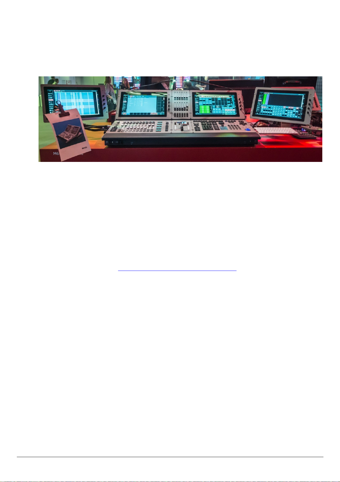
M-Series Components
M6
Screen Mounting Kit
M6 allows to attach VESA 100mm compatible screens to the outside of the desk, including the two screen
modules.
This allows for example to replace the internal screen with an additional playback module and use the M6 screen
on an external mounting arm, or add additional screens to the console as needed. The M6 supports a total of
four displays.
M6 offers support for two external screen mounting kits.
To accomplish this a few items are required:
1. Martin M6 screen mount kit, PN 91613109
Included items: console bracket, screen bracket, 4 screws, cable
2. Manfrotto Magic Arm 244N http://www.manfrotto.com/variable-friction-arm
3. Martin M-Series Touch Screen Module PN 91613108 (or other VESA compatible screen)
3
© 2013 Martin Professional A/SM-Series 3.0
Page 4

To mount a screen place it on a flat surface. Position the thumbwheel sideways and attach the screen bracket with
the supplied allen screws to the back of the screen and fasten them tightly.
4
© 2013 Martin Professional A/SM-Series 3.0
Page 5

Next, attach the console bracket to the side of the console just under the carrying handle and screw down the
thumbwheel for a tight fit.
The feet of the bracket have to be supported by the same flat and even surface the console is standing on.
5
© 2013 Martin Professional A/SM-Series 3.0
Page 6

Place the Magic Arm into the back of the screen mount and tighten the thumbscrew to it fits the ridge in the pin
of the arm. Then place the screen and arm into the mounting hole on the console bracket.
Use one hand to stabilize the screen and move it into a rough position, then tighten the center screw of the
Magic Arm down so the screen does not move.
Adjust the screen position as necessary for a comfortable working position.
Connect the provided cable to the M6. Make sure the console is turned off before connecting the cable.
First, connect the USB connection to the back of the desk, then connect the USB connection to the back of the
screen.
Next, connect the Display Port connection on the desk, then the screen.
Lastly, connect the 10-pin power plug to the screen, then to the desk.
Power up the console and confirm proper operation. The dimensions of the external screen may have to adjusted
set using the Display Settings menu in the M6.
6
© 2013 Martin Professional A/SM-Series 3.0
Page 7

Accessory Mounts
The left and right edge of the M6 allow mounting of various support arms.
Solutions can be found for keyboard holders, drink holders, paper clips, camera mounts and others.
Martin does not sell such accessories, they have to be provided by the user.
The accessory points are provided as 1/4"-20 threads, commonly found on the bottom of cameras to mount
tripods.
The maximum depth of the screw is 10mm, or 3/8 of an inch. Each side has three support points
Examples
The provides links are suggestions where to find such accessories. Martin is not associated with these companies.
Any arms and holders utilizing the 1/4"-20 thread will work. Some items may not be available in all countries.
Keyboard holder (fits Apple Mini keyboard)
2x 6" stainless steel rod
7
© 2013 Martin Professional A/SM-Series 3.0
Page 8

Paperclip or Camera
Camera Arm
8
© 2013 Martin Professional A/SM-Series 3.0
Page 9

RAM Mount
1" Ball with 1/4"-20 post
4" Arm
Drink Holder or Ashtray
Tablets and iPad
Clipboard Case
http://www.rammount.com/
RAM Mounts offers a large variety of mounting options in the "B" size series.
Once a 1" ball is attached to the desk, anything from RAM Mount can be used. Here are some basic examples:
9
© 2013 Martin Professional A/SM-Series 3.0
Page 10

www.martin.com • Olof Palmes Allè 18 • 8200 Aarhus N • Denmark
Tel: +45 8740 000 • Fax +45 8740 0010
 Loading...