

Page 1
LC Plus
LED Video Display
Panel
Installation and Safety
Manual
TM
Page 2
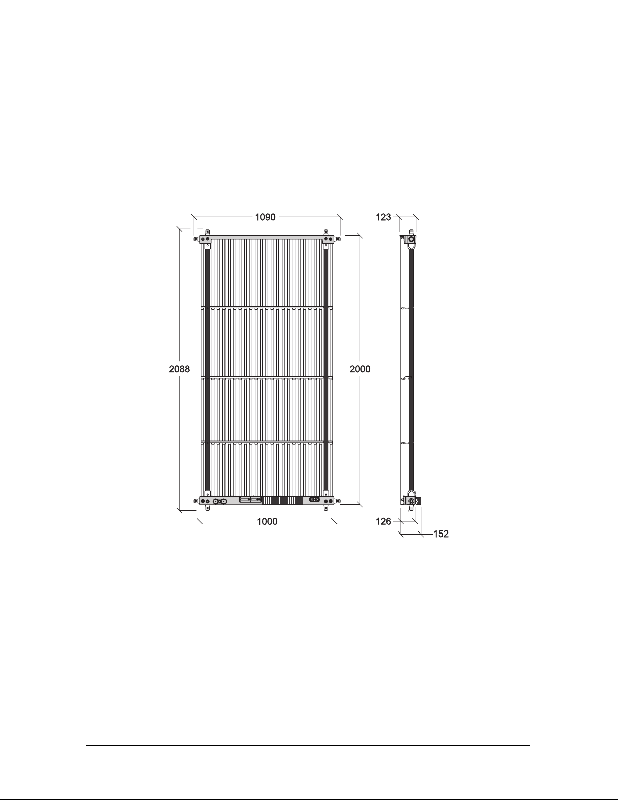
Dimensions
All dimensions are in millimeters
©2009 Martin Professional A/S. Information subject to change without notice. Martin Professional A/S and all affiliated companies disclaim liability for
any injury, damage, direct or indirect loss, consequential or economic loss or any other loss occasioned by the use of, inability to use or reliance on the
information contained in this manual. The Martin logo, the Martin name and all other trademarks in this document pertaining to services or products by
Martin Professional A/S or its affiliates and subsidiaries are trademarks owned or licensed by Martin Professional A/S or its affiliates or subsidiaries.
P/N 35000218, Rev. C
Page 3
Safety Information 3
Safety Information
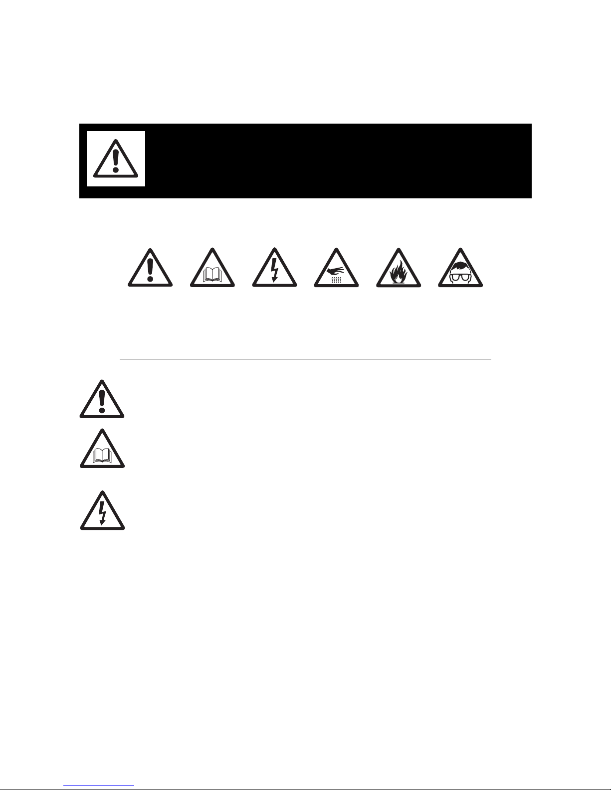
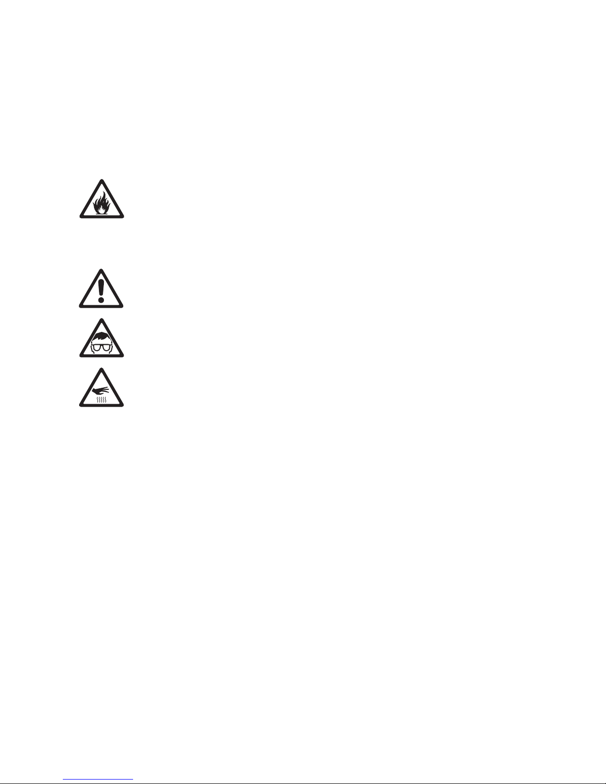
The following symbols are used to identify important safety information on the product and in this manual:
This product is for professional use only. It is not for household use.
This product presents risks of severe injury or death due to fire hazards, electric shock and falls.
Read this manual before installing, powering or servicing this product, follow the safety precautions listed
below and observe all warnings in this manual and printed on the product.
If you have questions about how to operate the fixture safely, please contact your Martin supplier or call the
Martin 24-hour service hotline on +45 8740 0000, or in the USA on 1-888-tech-180.
PROTECTION FROM ELECTRIC SHOCK
• Connect the product to AC mains power within the range 200 - 240 V nominal at 50 or 60 Hz only.
• Disconnect the entire installation from power and ensure that power cannot be reconnected, even
accidentally, before carrying out any installation or maintenance work.
• Disconnect the product from power when not in use and if you suspect that a fuse has blown.
• Always ground (earth) the product electrically.
• Use only a source of power that complies with local building and electrical codes and has both overload
and ground-fault (earth-fault) protection.
• Connect LC Plus panels to AC power using only 16 A-rated industrial Type B power plugs and socket
outlets that comply with IEC 60309 (or a comparable national standard) and provide an electrical
connection to ground (protective earth).
• Connect LC Plus panels to AC power and to each other using the 16 A rated, UL-listed, 16 AWG cables
supplied by Martin for this product. Replacement power cables from other sources can be used as an
alternative, but they must be 3-conductor Hypalon or neoprene rubber-jacket, approved for a current of
16
A and temperature of 90° C (194° F) minimum. Replacement cables must also be 16 AWG minimum
and UL-listed in North America or have conductor size 1.5 mm² minimum in other regions.
• Socket outlets used to supply LC Plus panels with power or external power switches must be located near
the panels and easily accessible so that the panels can easily be disconnected from power.
• Do not connect any other device than other LC Plus panels to the power output (throughput) connector in
the base of the LC Plus.
WARNING!
Read the safety precautions in this section before
installing, powering, operating or servicing this
product.
Warning!
Safety hazard.
Risk of severe
injury or death.
Warning!
Refer to
manual before
installing,
powering or
servicing.
Warning!
Hazardous
voltage. Risk of
lethal or severe
electric shock.
Warning!
Hot surface. Do
not touch.
Warnin g!
Fire hazard.
Warning!
Emission
hazardous to
eyesight.
Page 4
4 LC Plus user manual
• Connect no more than five LC Plus panels in total to AC mains power in one chain using the power output
(throughput) connectors in the base of the product.
• When using the product in a wet location, use only the Amphenol IP67-rated connectors supplied by
Martin and specified in this manual. Seal all unused connectors with their IP67-rated caps.
• Before using the product, check that all power distribution equipment and cables are in perfect condition
and rated for the current requirements of all connected devices.
• Do not use the product if the power cable or a power plug is in any way damaged, defective or showing
signs of overheating.
• Do not attempt to remove any LED tube or open any cover.
• Refer any service operation not described in this manual to a qualified technician.
PROTECTION FROM FIRE
• Provide a minimum clearance of 30 cm (11.8 in.) around the heatsink at the back of the panel base.
• Do not stick filters, masks or other materials directly onto LED tubes.
• Do not modify the product in any way not described in this manual.
• Install only genuine Martin parts in or on the product unless an alternative is described in this manual.
• Do not operate the product if the ambient temperature (Ta) exceeds 40° C (104° F).
PROTECTION FROM INJURY
• Ensure that any structure used for support as well as all fastening and connecting hardware can hold at
least 10 times the weight of all supported devices and equipment.
• When lifting a panel, suspend it using two approved conical couplers with eyebolts. Use two approved
conical couplers to suspend the panel from the supporting structure. Do not suspend panels using any
other method of attachment than those described in this manual.
• When stacking panels on top of each other, fasten panels securely to prevent them from tipping or falling
and do not stack more than:
- Nine LC Plus 1140 panels standing upright
- Eight LC Plus 1140 panels lying on their side
- Seven LC Plus 2140 panels standing upright, or
- Five LC Plus 2140 panels lying on their side
• When suspending in a curtain with panels hanging from each other, use two conical couplers to suspend
each panel and do not suspend more than:
- Eight LC Plus 1140 panels hanging upright
- Eight LC Plus 1140 panels hanging sideways
- Six LC Plus 2140 panels hanging upright, or
- Six LC Plus 2140 panels hanging sideways
• When mixing LC Plus 1140 and LC Plus 2140 products in a stack or curtain, observe the maximum limit
for LC Plus 2140 panels stated above.
• Use a minimum of two approved secondary attachments (such as safety cables) to secure each product
as described in this manual. Safety cables must be approved by an official body such as TÜV as a safety
attachment for the weight of all the fixtures it secures. Safety cables must comply with EN 60598-2-17
Section 17.6.6 and be capable of bearing a static suspended load ten times the weight of the fixture.
• Check that all external covers and rigging hardware are securely fastened.
• Block access below the work area and work from a stable platform whenever installing, servicing or
moving the product.
• Do not look at lit LEDs from a distance of less than 40 cm (1 ft. 4 in.) without suitable protective eyewear.
• Do not view lit LEDs with optical instruments that may concentrate the light output.
• The surface of the heatsink in the base of the panel can become hot, over 80° C (176° F), during normal
operation. Install panels in a restricted area only in order to ensure that accidental contact by members of
the public is impossible.
Page 5

Contents
Dimensions . . . . . . . . . . . . . . . . . . . . . . . . . . . . . . . . . . . . . . . . . . . . . . . . . . . . . . . . . . . . . . . . . . . . . . . . 2
Safety Information. . . . . . . . . . . . . . . . . . . . . . . . . . . . . . . . . . . . . . . . . . . . . . . . . . . . . . . . . . . . . . . . . . 3
Connections overview . . . . . . . . . . . . . . . . . . . . . . . . . . . . . . . . . . . . . . . . . . . . . . . . . . . . . . . . . . . . . . 6
Introduction . . . . . . . . . . . . . . . . . . . . . . . . . . . . . . . . . . . . . . . . . . . . . . . . . . . . . . . . . . . . . . . . . . . . . . . . 7
Unpacking . . . . . . . . . . . . . . . . . . . . . . . . . . . . . . . . . . . . . . . . . . . . . . . . . . . . . . . . . . . . . . . . . . . . . . . . 7
Using for the first time . . . . . . . . . . . . . . . . . . . . . . . . . . . . . . . . . . . . . . . . . . . . . . . . . . . . . . . . . . . . . . . 8
LC Plus flightcases . . . . . . . . . . . . . . . . . . . . . . . . . . . . . . . . . . . . . . . . . . . . . . . . . . . . . . . . . . . . . . . . . 8
Physical installation . . . . . . . . . . . . . . . . . . . . . . . . . . . . . . . . . . . . . . . . . . . . . . . . . . . . . . . . . . . . . . . . 9
Standing installation. . . . . . . . . . . . . . . . . . . . . . . . . . . . . . . . . . . . . . . . . . . . . . . . . . . . . . . . . . . . . . . . . 9
Flying from a truss, bar or other structure . . . . . . . . . . . . . . . . . . . . . . . . . . . . . . . . . . . . . . . . . . . . . . . 10
AC power . . . . . . . . . . . . . . . . . . . . . . . . . . . . . . . . . . . . . . . . . . . . . . . . . . . . . . . . . . . . . . . . . . . . . . . . . 12
Power and fuses . . . . . . . . . . . . . . . . . . . . . . . . . . . . . . . . . . . . . . . . . . . . . . . . . . . . . . . . . . . . . . . . . . 12
Power connection . . . . . . . . . . . . . . . . . . . . . . . . . . . . . . . . . . . . . . . . . . . . . . . . . . . . . . . . . . . . . . . . . 13
P3 communication link . . . . . . . . . . . . . . . . . . . . . . . . . . . . . . . . . . . . . . . . . . . . . . . . . . . . . . . . . . . . 16
Planning the P3 link . . . . . . . . . . . . . . . . . . . . . . . . . . . . . . . . . . . . . . . . . . . . . . . . . . . . . . . . . . . . . . . . 16
Connecting the P3 link. . . . . . . . . . . . . . . . . . . . . . . . . . . . . . . . . . . . . . . . . . . . . . . . . . . . . . . . . . . . . . 18
Configuration and testing . . . . . . . . . . . . . . . . . . . . . . . . . . . . . . . . . . . . . . . . . . . . . . . . . . . . . . . . . . 19
Control panel, display and status indicators . . . . . . . . . . . . . . . . . . . . . . . . . . . . . . . . . . . . . . . . . . . . . 19
Resetting and rebooting panels. . . . . . . . . . . . . . . . . . . . . . . . . . . . . . . . . . . . . . . . . . . . . . . . . . . . . . . 21
Service and maintenance. . . . . . . . . . . . . . . . . . . . . . . . . . . . . . . . . . . . . . . . . . . . . . . . . . . . . . . . . . 22
Cleaning. . . . . . . . . . . . . . . . . . . . . . . . . . . . . . . . . . . . . . . . . . . . . . . . . . . . . . . . . . . . . . . . . . . . . . . . . 22
Installing new software . . . . . . . . . . . . . . . . . . . . . . . . . . . . . . . . . . . . . . . . . . . . . . . . . . . . . . . . . . . . . 22
Troubleshooting . . . . . . . . . . . . . . . . . . . . . . . . . . . . . . . . . . . . . . . . . . . . . . . . . . . . . . . . . . . . . . . . . . 23
Specifications . . . . . . . . . . . . . . . . . . . . . . . . . . . . . . . . . . . . . . . . . . . . . . . . . . . . . . . . . . . . . . . . . . . . . 24
Page 6
6 LC Plus user manual
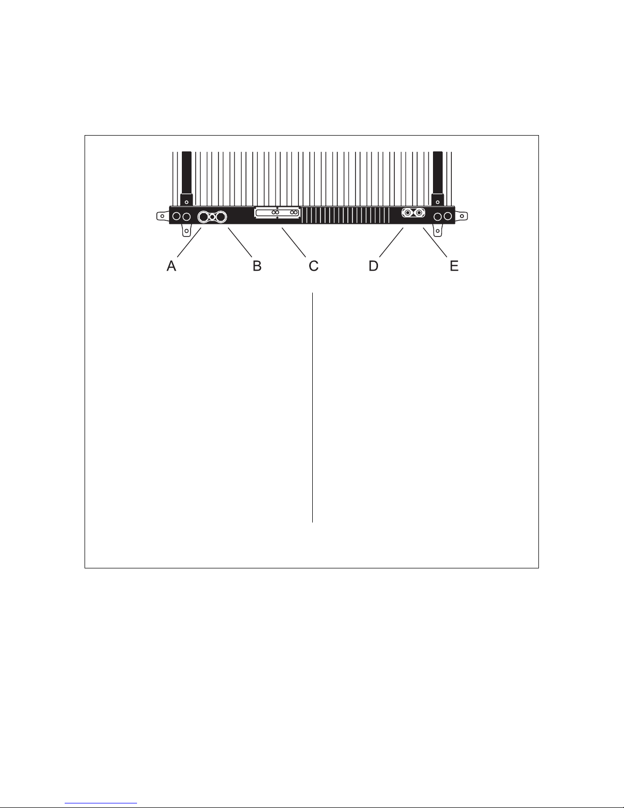
Connections overview
A - Ethernet port 1
Used for bi-directional P3 system communication.
Accepts an Amphenol IP67-rated Ethernet cable
connector (or a standard Ethernet connector for
indoor use only).
Warning! All connectors that are not in use
must be sealed at all times with the caps
provided.
B - Ethernet port 2
Used for bi-directional P3 system communication.
Accepts an Amphenol IP67-rated Ethernet cable
connector (or a standard Ethernet connector for
indoor use only).
Warning! All connectors that are not in use
must be sealed at all times with the caps
provided.
C - Control panel and LED display
See “Using the control panel and control panel
display” on page 19 for details.
D - Power input connector
Used to supply power to the panel. Accepts an
Amphenol IP67- rated power input (female) cable
connector.
E - Power throughput (output) connector
Used to relay power to another LC Plus panel.
Accepts an Amphenol IP67-rated power output
(male) cable connector. The voltage and
frequency available at this connector are the
same as those applied at the power input
connector D.
Warning! A maximum of FIVE LC Plus 2140
panels in total or TEN LC Plus 1140 panels in
total may be connected to power in one chain
that draws power through the first panel’s
power input connector. All connectors that
are not in use must be sealed at all times with
the caps provided.
Figure 1: Connections
Page 7

Introduction 7
Introduction
This Installation and Safety Manual explains how to install, configure and maintain Martin™ LC
Plus™ video panels. The Safety section contains important information about safety precautions.
The installation section contains details of how to physically install panels and cables, connect
panels to power and prepare for connection to a Martin™ P3-100™ System Controller and video
source.
For information about installing and using the P3-100 System Controller, see the P3-100 user
documentation supplied with the P3-100.
All LC Plus Series and P3-100 user documentation is also available for download free of charge from
the Product Support area at www.martin.com
Thank you for selecting the Martin™ LC Plus, a product from the LC™ Series of modular LED-based video
display panels from Martin™. This product features:
• 40 mm pixel pitch (seamless image at approx. 30 m)
• 3000 Cd/m2 (3000 nits) effective light output at 25° C (77° F)
• Rich RGB color
• 25 x 50 pixels (LC Plus 2140) or 25 x 25 pixels (LC Plus 1140) per panel image resolution
• Color resolution of 16 bits per color
• 100° x 40° viewing angle
• Silent convection cooling
• P3 signal in/out via 'daisy-chainable' Amphenol IP67-rated ruggedized bayonet-mount RJ-45 connectors
• Auto-sensing 200 - 240 VAC nominal switch mode power supply
• Amphenol IP67-rated ruggedized threaded locking power connectors
• Prolyte CCS6 conical coupler system for fast installation
For the latest firmware updates, documentation, and other information about this and all Martin
Professional™ products, please visit the Martin website at http://www.martin.com
Comments or suggestions regarding this document may be e-mailed to service@martin.dk or posted to:
Technical Documentation
Service Department
Martin Professional A/S
Olof Palmes Allé 18
DK-8200 Aarhus N
Denmark
Warning! Read “Safety Information” on page 3 before installing, powering, operating or
servicing the LC Plus.
This is an ITE Class A product. In a domestic environment this product may cause radio interference, in
which case the user may be required to take appropriate measures.
Unpacking
LC Plus Series products are packaged either in sets of 4 panels in a 4-unit flightcase or as single panels in
a cardboard box. The following items are included.
In the cardboard box:
• 4 x conical couplers (Prolyte CCS6 system): P/N 21021150
• 8 x threaded spigots* for LC Plus conical coupler: P/N 08330127
• 8 mm hex key for threaded spigots: P/N 50520619
• 5 m (16.4 ft.) power input cable with IP67 input connector for single-phase power: P/N 11521030
• 5 m (16.4 ft.) power input cable with IP67 input connector for 2-phase power: P/N 11521034
• 1.5 m (4.9 ft.) power throughput cable with IP67 connectors for single-phase power: P/N 11521031
• 1.5 m (4.9 ft.) power throughput cable with P67 connectors for 2-phase power: P/N 11521033
Page 8
8 LC Plus user manual
• 2.5 m (8.2 ft.) Ethernet patch cable with IP67 RJ-45 connectors: P/N 11840146
• 1.5 m (4.9 ft.) Ethernet patch cable with IP67 RJ-45 connectors: P/N 11840140
• LC Plus Installation and Safety Manual: P/N 35000218
In the 4-unit flightcase:
• 16 x conical couplers (Prolyte CCS6 system): P/N 21021150
• 32 x threaded spigots* for LC Plus conical couplers: P/N 08330127
• 8 mm hex key for threaded spigots: P/N 50520619
• 5 m (16.4 ft.) power input cable with IP67 input connector for single-phase power: P/N 11521030
• 5 m (16.4 ft.) power input cable with IP67 input connector for 2-phase power: P/N 11521034
• 4 x 1.5 m (4.9 ft.) power throughput cables with IP67 connectors for single-phase power: P/N 11521031
• 4 x 1.5 m (4.9 ft.) power throughput cables with IP67 connectors for 2-phase power: P/N 11521033
• 4 x 2.5 m (8.2 ft.) Ethernet patch cables with IP67 RJ-45 connectors: P/N 11840146
• 4 x 1.5 m (4.9 ft.) Ethernet patch cables with IP67 RJ-45 connectors: P/N 11840140
• LC Plus Installation and Safety Manual: P/N 35000218
* Threaded spigots for conical couplers in the Martin LC Plus are not interchangeable with the threaded
spigots for the standard Martin LC Series.
Important! Do not throw away the protective shock-absorbing materials from the flightcase when you
unpack panels. The protective materials will be needed when panels are repacked in the
flightcase.
Using for the first time
Before applying power to the panel:
• Carefully review “Safety Information” on page 3.
• Check that the local AC power voltage is within the ranges listed on the serial number label and in “Power
and fuses” on page 12.
• To supply the panel with power, use the supplied power cable or install an Amphenol C016 20 D 003 100
12 connector on a UL-listed, minimum 16 AWG or 1.5 mm
2
SJT (or better) power cable as described in
“Power connection” on page 13.
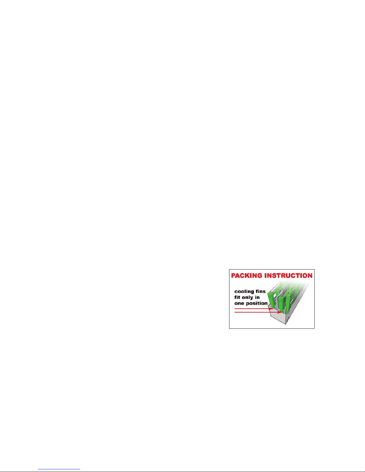
LC Plus flightcases
Important! To ensure that LC Plus panels can withstand the shocks
that normally occur during transport, they must be
packed in a Martin flightcase and transported in an
upright position following the instructions in the
flightcase (see
Figure 2). Damage caused to panels that
are incorrectly packed or exposed to abnormal shocks is
not covered by the product warranty.
When removing panels from the flightcase, keep all protective
material for use when repacking.
Important! Transport and store flightcases standing in an upright
position only. Do not transport flightcases lying flat on
their side.
Figure 2: Flightcase packing
Page 9
Physical installation 9
Physical installation
Warning! Read “Safety Information” on page 3 before installing the LC Plus.
Warning! The safety and suitability of lifting equipment, installation location, anchoring method,
mounting hardware and electrical installation is the responsibility of the installer. All local
safety regulations and legal requirements must be observed when installing and connecting the
LC Plus.
Warning! Installation must be carried out by qualified professionals only. Contact your Martin
supplier for assistance if you have any questions about how to install this product safely.
Warning! The surface of the heatsink in the base of the panel can become hot during normal
operation. Install so as to prevent accidental contact by members of the public.
Warning! Use two conical couplers to fasten a panel to a supporting structure or to another
panel. When lifting a panel, use two conical couplers as attachment points for lifting gear. Do
not use only one conical coupler or any other method to suspend, lift or attach panels. Do not
use the ventilation holes in the top rail or the LED tubes as attachment points.
Warning! Secure every panel with two safety cables that are approved for the weight they secure
and installed as described in this manual.
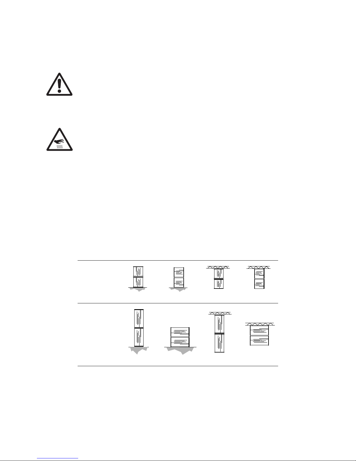
Warning! When stacking panels one on top of another or suspending panels one from another,
do not exceed the limits given in Figure 3. If an installation needs to be taller than the limits
given in Figure 3, additional support points must be provided to bear the weight of the
additional panels.
Warning! When stacking panels, secure them so that they cannot tip or fall.
The LC Plus can be installed in a standing position alone or stacked, flown in a vertical curtain or
suspended in any orientation from a truss or supporting structure.
Standing installation
See Figure 3. One vertical stack with LC Plus 1140 panels resting on each other may contain a maximum of
nine LC Plus 1140 panels stacked upright or eight LC Plus 1140 panels stacked on their sides.
Stacked
upright
Stacked
on side
Suspended
upright
Suspended
on side
LC Plus 1140
Max. 9 Max. 8 Max. 8 Max. 8
LC Plus 2140
Max. 7 Max. 5 Max. 6 Max. 6
Figure 3: Safety limits for stacking and suspending attached panels
Page 10

10 LC Plus user manual
One vertical stack with LC Plus 2140 panels resting on each other may contain a maximum of seven LC
Plus 2140 panels stacked upright or five LC Plus 2140 panels stacked on their sides.
An unlimited number of stacks of panels may be installed alongside each other.
If you install panels in a standing position:
1. Check that any structure or equipment used for support can bear at least 10 times the weight of all the
panels, clamps, cables, auxiliary equipment, etc. that will be placed on it.
2. Make sure that there will be at least 30 cm (11.8 in.) of free space and unrestricted airflow to and around
the heatsink fins in the base of the panels.
3. Check that there are no combustible materials within 0.5 m (20 in.) of the panels when installed, and that
there are no flammable materials nearby.
4. Fasten panels securely so that they cannot tip or fall. Panels are not safe if left free-standing.
Flying from a truss, bar or other structure
See Figure 3. One vertical curtain with LC Plus 1140 panels suspended from each other may contain a
maximum of eight panels. One vertical curtain with LC Plus 2140 panels suspended from each other may
contain a maximum of six panels. These limits apply to panels both when suspended in an upright position
and when suspended on their sides.
An unlimited number of curtains of panels may be installed
alongside each other
.
To fly panels from a rig or other structure:
1. Check that the structure can bear at least 10 times the
weight of all the panels, clamps, cables, auxiliary equipment,
etc. that it will have to support.
2. See Figure 4. Check that the structure will not flex under the
weight of the panels. Hanging panels from a structure that is
not straight will place a strain on panels. Damage caused to
panels by mechanical stress is not covered by the product
warranty.
3. Check that there are no combustible materials within 0.5 m
(20 in.) of the panels when installed, and that there are no
flammable materials nearby.
4. Install two conical couplers in the top of the first panel and
install two rigging clamps or eyebolts on the couplers.
5. Block access under the work area. Working from a stable
platform, hang the panel by fastening the rigging clamps or
eyebolts to the truss or structure.
6. See Figure 5. Do not use the ventilation holes
(arrowed) in the top rail to support the weight of
panels when lifting or installing. The only
permitted method of supporting the weight of
panels is by means of two conical couplers
fastened into the coupler sockets in the top rail
and secured with spigots (as shown in
Figure 7
on page 11).
Figure 4: Avoiding stress on panels
Figure 5: Holes for ventilation only
Page 11

Physical installation 11
7. As soon as a panel is fastened in place, install
two safety cables to secure it. Safety
attachments must be able to bear at least 10
times the weight of all the panels they secure.
See
Figure 6. Loop safety cables in a
figure-of-eight around vertical side columns
and the supporting structure or the panel
above so that if a rigging clamp or conical
connector fails, the weight of the panels will be
held by the vertical columns and the blocks
the columns are anchored in, and not by the
panel bases or top rails.
8. See Figure 7. Continue hanging panels,
attaching them with conical couplers (A)
secured with threaded spigots (B) as shown in
Figure 7. As soon as a panel is added to an
array, secure it with two safety attachments.
Figure 6: Panel-to-panel safety cable attachment
Figure 7: Conical coupler system
A
A
B
B
B
B
Page 12

12 LC Plus user manual
AC power
Warning! The safety of the installation is the responsibility of the installer. Read “Safety
Information” on page 3 before creating an installation or connecting an LC Plus panel to AC
mains power. Disconnect the entire installation from power before carrying out installation
work.
Warning! A maximum of FIVE LC Plus 2140 panels in total or TEN LC Plus 1140 panels in total
may be interconnected using power throughput connectors to form one chain that draws power
via the first panel’s power input cable. If you do not respect these limits you will overload cables
and components and create a serious safety hazard. Each time you reach the maximum
permitted number of interconnected panels in one daisy-chain and want to supply more panels
with power, you must create a new daisy-chain that draws power from a separate power outlet.
Warning! For protection from electric shock, the panel must be grounded (earthed). Power
distribution circuits must be fitted with a current overload fuse or circuit breaker and
ground-fault (earth-fault) protection.
Warning! When connecting LC Plus panels to single-phase power, use the supplied
single-phase power input and throughput cables with black connector shells. When connecting
to 2-phase power, use the supplied 2-phase power input and throughput cables with blue
connector shells.
Warning! LC Plus panels do not have a power on/off switch. They are powered on as soon as
mains power is applied to the power input connector and remain powered on until mains power
is shut down at source or disconnected from the panel. The external power switch or power
outlet socket must be located near the LC Plus and easily accessible so that power to the LC
Plus can easily be shut down or disconnected if necessary.
Important! Connect the panels in the installation and the P3 controller to AC mains power at the
same outlet point in the power distribution circuit, or you may experience ground/earth loop
problems or create differences in potential that can damage devices. Damage caused by
differences in potential if devices are incorrectly connected to power is not covered by the
product warranty.
Power and fuses
Warning! Fuses are not user-replaceable. Contact Martin Professional for assistance if you
suspect that a fuse has blown.
Warning! Double pole/neutral fusing.
The LC Plus features an auto-sensing switch-mode power supply that accepts 200-240 V nominal AC mains
power at 50 or 60 Hz. Connect the panel to power that is within this voltage range only.
The LC Plus can be connected to mains power in either:
• a single-phase 200-240 VAC system, or in
• a 3-phase delta system or split-phase mid-point neutral system using two phases to obtain 200-240 VAC.
Power and current figures are given in “Typical power and current” on page 25. Allow a sensible safety
margin when calculating the AC mains power distribution circuits current headroom required for an LC Plus
installation.
Each LC Plus 2140 panel is protected by one 10 AT (slow-blow) main fuse when connected using the
supplied single-phase power cables and protected by two 10
AT (slow-blow) main fuses when connected
using the supplied 2-phase power cables. Fuses are not user-replaceable.
Inrush current
Inrush current peaks are unlikely to occur at exactly the same time in multiple panel installations and only
have a duration of a few microseconds, but bear in mind that inrush current when powering on may cause
unintentional tripping of circuit-breakers, especially if these have poor resistance to momentary current
peaks.
Page 13

AC power 13
Power connection
Power is supplied to the panel via the input socket (see D in Figure 1 on page 6). This socket accepts an
Amphenol C016 20 D 003 100 12 cable connector (female, IP67- rated).
Power can be relayed to another LC Plus panel via the throughput socket (see E in Figure 1 on page 6).
This socket accepts an Amphenol C016 20 H 003 100 12 cable connector (male, IP67- rated).
Warning! A maximum of five LC Plus 2140 panels in total or ten LC Plus 1140 panels in total may
be interconnected using power throughput connectors to form one chain that draws power via
the first panel’s power input cable.
Two types of power input and power throughput cable are supplied with each panel (see Figure 8):
• EU color-coded cables fitted with connectors with a black shell. You must use these input and throughput
cables when using single-phase AC mains power.
• US color-coded cables fitted with connectors with a blue shell. You must use these input and throughput
cables when using two-phase AC mains power.
All cables are 16 A rated, UL-listed, 16 AWG.
Table 1 on page 15 gives details of the standard wiring color codes used in these two cable types, as well as
common pin identification symbols. If you have any doubts about proper installation, consult a qualified
electrician.
Separate Amphenol connectors and replacement power cables with Amphenol connectors installed are
available from your Martin supplier.
The supplied power cables can be replaced with cables from other sources, but replacement cables must be
3-conductor with a Hypalon or neoprene rubber jacket, approved for a current of 16 A and temperature of
90° C (194° F) minimum. Replacement cables must also be minimum 16 AWG and UL-listed in North
America or have conductor size minimum 1.5 mm² in other regions.
To connect an Amphenol power cable connector to an LC Plus panel, line up the keys in the cable connector
with the slots in the corresponding chassis connector in the rear of the panel base (D or E in
Figure 1 on
page 6), push the cable connector firmly into the chassis connector, then twist the locking ring on the cable
connector clockwise to screw the connectors together and form a waterproof and dustproof seal.
Any connectors that are not being used must be sealed with their caps at all times.
There is no power on/off switch on LC Plus panels. Apply and shut down power using an external switch at
the power outlet or at the main switchboard. Make sure that the external switch is near the panels and easily
accessible so that power to the panels can easily be shut down if necessary. Do not power panels on or off
by inserting or removing live power connectors, as this will cause arcing at the connector contacts that may
damage devices and connectors.
Figure 8: Power cable connectors
EU type,
for single-phase power
US type,
for 2-phase power
black blue
Page 14

14 LC Plus user manual
Installing power cable connectors
Installing Amphenol connectors
The Amphenol C016 ecomate series power cable connectors used with the LC Plus accept power cable
from 6 mm (0.24 in.) to 9 mm (0.35 in.) diameter when fitted with a standard cable gasket, or from 9 mm
(0.35 in.) to 12.5 mm (0.5 in.) diameter when fitted with an optional heavy gauge cable gasket.
If you need to install an Amphenol C016 series cable connector on a power cable for connection to an LC
Plus panel:
1. Ensure that the power cable is UL-listed, 16 AWG minimum in North America or 3 x 1.5 mm2 minimum
in other regions, 3-conductor Hypalon or neoprene rubber-jacket type, approved for a current of 16
A
and a temperature of 90° C (194° F) minimum.
2. Obtain a female cable connector (Amphenol C016 20 D 003 100 12) for power input or a male cable
connector (Amphenol C016 20 H 003 100 12) for power out/throughput.
3. See Figure 9. Pass the cable through the cable nut, correct gasket for the cable diameter, clamping ring
and back shell.
4. Strip 18-19 mm (0.70-0.75 in.) of cable jacket and then strip 7-8 mm (0.27-0.31 in.) of insulation from
each conductor (as indicated for screw contacts with internal cable retention in Figure 9). Twist the bared
strands at the end of each conductor to strengthen them.
5. Fasten the conductors in the cable into the screw terminals in the male or female contact insert as
follows:
When installing an Amphenol C016 series power connector in a single-phase system:
- Fasten the green/yellow ground (earth) conductor in the screw terminal marked Drain or .
- Fasten the blue neutral conductor in the screw terminal marked 2.
- Fasten the brown live conductor in the screw terminal marked 1.
- Do not connect anything to the terminal marked 3.
-OUNTING)NSTRUCTIONSTRAIGHTCABLECONNECTOR
ADDITIONALLY
INCLUDEDGASKET
CABLENUT
TIGHTENINGTORQUE
.M
TIGHTENINGTORQUE.M
-OUNTING)NSTRUCTIONS
B
A
3TRIPPING,ENGTHS
3CREWCONTACTS
WITHINTERNALCABLERETENTION
WITHOUTINTERNALCABLERETENTION
3OLDERCONTACTS
WITHINTERNALCABLERETENTION
WITHOUTINTERNALCABLERETENTION
#RIMPCONTACTS nMM
nMM
WITHINTERNALCABLERETENTION
WITHOUTINTERNALCABLERETENTION
0%MMENDSPLICERECOMMENDED
-EASUREB
-EASUREA
CLAMPINGRINGWITHMOUNTEDGASKET
BACKSHELL
TIGHTENINGTORQUE
.M
INTERNAL
STRAINRELIEF
MALECONTACT
INSERTWITH
LOCKINGRING
FEMALECONTACT
INSERTWITH
LOCKINGRING
Figure 9: Amphenol power cable connector assembly instructions
Content in this illustration is copyright ©Amphenol-Tuchel Electronics GmbH and used by permission. These illustrations may not
be reproduced in any form without the written permission of Amphenol-Tuchel Electronics GmbH.
Page 15

AC power 15
When installing an Amphenol C016 series power connector in a 2-phase system:
- Fasten the green/yellow ground (earth) conductor in the screw terminal marked Drain or .
- Fasten the black phase 1 conductor in the screw terminal marked 1.
- Fasten the white phase 2 conductor in the screw terminal marked 3.
- Do not connect anything to the terminal marked 2.
6. Tighten the internal strain relief clamp onto the cable.
7. Tighten the back shell onto the male or female contact insert.
8. Tighten the cable nut onto the back shell.
Power plugs and power outlet sockets
A power plug must be installed on the power input cable so that
you can connect LC Plus panels to AC mains power. Install a
grounding-type (earthed) industrial 3-prong type B plug (see
Figure 10) that complies with IEC 60309 or a comparable national
standard and is rated 16 A minimum, and use corresponding
power outlet sockets. Follow the plug and socket manufacturer’s
instructions and all locally applicable laws and electrical safety
codes.
When installing a power plug in a single-phase system:
• Connect the green/yellow ground (earth) conductor to the
terminal marked
or .
• Connect the brown live conductor to the terminal marked L.
• Connect the blue neutral conductor to the remaining terminal.
When installing a power plug in a 2-phase system:
• Connect the green ground (earth) conductor to the terminal marked or .
• Connect the black phase 1 conductor to the terminal marked L.
• Connect the white phase 2 conductor to the remaining terminal.
Wire color
(EU color code)
Wire color
(US color code) Pin Symbol Screw (US)
brown black live
L
yellow or brass
blue white neutral
N
silver
yellow/green green ground (earth) or green
Table 1: Wire colors and pin identification
Figure 10: Industrial IEC 60309 type
B power plug
Page 16

16 LC Plus user manual
P3 communication link
LC Plus series panels communicate using the Martin™ P3™ signal format via Ethernet cable. The P3
signal contains both video data and command signals.
Each LC Plus panel has two RJ-45 Ethernet sockets (see A and B in Figure 1 on page 6) for connection to
the P3 link. All sockets are bi-directional, handling both P3 signal input and output.
Cable and connector types
Use good-quality CAT 5e or better STP (shielded twisted pair) Ethernet cable for the P3 link in an
installation with LC Plus panels. RJ-45 connectors should be shielded type, with the shield around the
connector terminals electrically connected to the cable shield.
The two Ethernet sockets on each panel are mounted in Amphenol IP67-rated reverse bayonet-mount
housings. For outdoor use, RJ-45 plugs installed in Amphenol RJF RB 6 housings (as supplied with the
panel) must be used at all times. Any unused sockets must be sealed with the cap attached to each socket.
For indoor use in dry locations, non IP-rated standard RJ-45 Ethernet connectors and patch cables may be
used.
Suitable IP67-rated and non IP-rated patch cables in various lengths and suitable connector housings are
available from Martin (see
“Accessories” on page 26).
Planning the P3 link
Figure 11 shows an example of P3 system layout.
Media source
As a media source, we recommend the use of a product from the Martin™ Maxedia™ series. Maxedia
products offer fast processors, advanced features, DVI output and an intuitive user interface. Besides a
Maxedia media server/processor, any video camera or video source with an S-video, composite video or
component video output can be used as a video source.
P3 link requirements in large installations
A single P3-100 system controller can drive up to 400 LC Plus 2140 panels, up to 800 LC Plus 1140 panels,
or any combination within a limit of 500 000 pixels, provided that Ethernet switches are used to split and/or
amplify the P3 signal as described in this section.
Using Ethernet switches to split the link into chains
See Figure 11. If the LC Plus installation consists of more than 50 panels, you must first run the P3 signal
output from the P3-100 System Controller to a 1 GB Ethernet switch. Divide the panels into separate
daisy-chains with no more than 50 panels on any single chain, and use the outputs from the Ethernet switch
to send the P3 signal to each chain.
Figure 11 shows a 1 GB Ethernet switch on the P3 link as an example, but the switch is not necessary if
there are 50 panels or less in the installation.
Using Ethernet switches to extend the link
See Figure 11. The maximum permitted cable length between any two devices on the P3 link before a
signal amplifier is required is 100 m (328 ft.) if good quality Ethernet cable is used for the link. A 1 GB
Ethernet switch on the P3 link is an ideal signal amplifier. If the P3 link will exceed the 100
m cable length
limit at any point in the installation, insert a switch to boost the signal. If necessary, more switches can be
added each time the link reaches the 100 m limit.
Figure 11 shows the 1 GB Ethernet switch inserted between two panels on the P3 link as an example only:
the switch can be inserted in any position on the link where the cable length between any two devices would
exceed 100 m.
More expensive, sophisticated switches tend to carry out additional processing that can cause latency. You
should therefore choose a relatively cheap unmanaged gigabit Ethernet switch.
Page 17

P3 communication link 17
P3 system layout: schematic overview
Figure 11: Schematic diagram of P3 system connections
DVI
Analog
video
Analog
video
Monitor
Mouse
Keyboard
P3-100 System Controller
P3 signal
1GB Ethernet
switch required
1GB Ethernet
switch required
100 m
Max. 50 panels per daisy-chain
if installation
exceeds 50 panels
if cable length
exceeds 100 m
cable
Page 18

18 LC Plus user manual
Connecting the P3 link
Warning! For outdoor or wet location use, use Amphenol RJF RB 6 housings (as supplied with
the panels) on all the RJ-45 plugs used for P3 signal input and out/throughput.
Important! Power all panels and devices off while making connections.
To connect the P3 link:
1. Plug an Ethernet patch cable running from the P3-100 System Controller’s P3 signal output socket into
one of the RJ-45 Ethernet ports on the first LC Plus panel (it does not matter which port you use, as both
P3 connectors can be used for input and output). In outdoor or wet locations, an IP67-rated Amphenol
RJF RB 6 housing must be installed on the RJ-45 plug.
2. Continue connecting panels to the P3 link in a daisy-chain by running Ethernet patch cables from the
first panel’s Ethernet 2 socket to the next panel’s Ethernet 1 socket, respecting the layout and guidelines
given earlier in this section.
3. When you have made all P3 and power connections, set up the panels as described in the P3-100 user
manual.
4. Any connectors that are not being used must be sealed with their caps at all times.
5. The system is now ready for power to be applied.
Page 19

Configuration and testing 19
Configuration and testing
This section covers the needs of the installer and technician only. It explains the options available for
configuration and testing of LC Plus panels, but it does not explain how to allocate addresses to panels or
the options available for displaying video. For details of these, see the P3-100 System Controller user
documentation.
When repacking panels in a Martin flightcase after operation, follow the instructions in the flightcase (see
“LC Plus flightcases” on page 8).
Control panel, display and status indicators
Basic configuration, status checking and testing without a P3-100 connected can be carried out using the
control panel and LED display on the back of the frame base.
Five LEDs give information about panel and system status.
Using the control panel and control panel display
The panel’s address appears in the 7-segment 4-character LED display when an LC Plus panel is powered
on.
The control panel is used as follows:
• To enter the control menus (see Tabl e 5 ), hold MENU pressed in for one second. The red status LED at
the bottom right of the panel will flash quickly to indicate that you are about to enter the control menus.
After a second, the panel address will fade out and the first control menu
Addr will fade in. The red status
LED at the bottom right of the panel will light constantly.
• To scroll between menus or options in menus such as values, press PREV and NEXT.
• To select a function or submenu or to confirm a selection, press ENTER.
• To escape a function or menu, press MENU.
If no buttons are pressed for 25 seconds, the menu indicator LED will start flashing slowly. If no buttons are
pressed for a further 5 seconds, the panel will automatically exit the control menus.
When exiting the menu system (either manually or automatically), the menu display will fade out and the
panel address display will fade in. The red status LED at the bottom right of the panel will now be off to
indicate that the control menus are disabled.
Figure 12: Control panel and control panel display
Page 20

20 LC Plus user manual
RGB overall status LED
One overall status RGB LED on the left of the display panel gives at-a-glance indication of panel status. This
LED indicates the following states:
Red status LEDs
Four small red status LEDs located around the display panel indicate the following states:
Panels communicate with each other to determine which devices are connected on the P3 link, so the ‘P3
command receive’ LED (middle left) can indicate that the panel is receiving commands another panel as
well as from a P3 system controller.
Panel address and status messages in the display panel
The following information appears in sequence in the display panel at start-up:
The boot process generally takes approximately 4 seconds. When it is completed, the panel displays its
address. It will continue to display its address permanently unless the control menus are activated.
Color Output Indication Action required
Blue Constant
Busy (e.g. booting up or writing to
flash memory)
Wait a moment for normal operation
to be resumed
Red Constant
Error. The panel has encountered a
fatal error and can not run.
Perform a factory reboot, followed by
a firmware upload
Red Flashing
Disconnected. A system controller
could not be found
Connect a system controller to the
network
Green Flashing
Ready. A system controller is present
on the network
Configure the system controller to
use this panel
Green Constant
Running. A system controller is using
this panel
None
Table 2: RGB status LED
Marking Location Indication
ETHER 1 Top left Ethernet port 1 link (flashes during activity)
ACTIVE Middle left Receiving P3 commands
ETHER 2 Bottom left Ethernet port 2 link (flashes during activity)
MENUS Bottom right Control menu system active
Table 3: Red status LEDs
Display Indication
Boot
Controller hardware is booting (displayed
briefly, so may not even be seen)
rSEt
Panel firmware is resetting
2140
Panel model number (either 2140 or 1140)
PLUS
Identifies panel as LC Plus.
Table 4: Start-up display messages
Page 21

Configuration and testing 21
Control menus
The following menu commands and options are available in the control panel:
Resetting and rebooting panels
If it becomes necessary to reset an LC Plus panel, it is possible to force a 'normal reboot' (which causes the
panel to reset and start up as it normally would when power is applied), or a 'factory reboot' (which causes
the panel to start up the original factory-programmed firmware). The factory reboot is a fail-safe way to
ensure the panel can be started up if there is a problem with the most recently uploaded firmware. It should
not be required during normal operation.
Normal reboot: Press all four control panel buttons simultaneously. The display will show rSet. Release
the buttons within five seconds. The panel will boot up normally as though power has just been applied.
Factory reboot: Press and hold all four buttons for 5 seconds or longer. The panel will display FAct. When
the buttons are released, the panel display will alternate between FAct and LoAd a few times to indicate
that the factory firmware is about to be loaded. The panel will then boot the original factory-programmed
firmware.
Note that performing a factory reboot will only cause the panel to boot the factory firmware once. At the next
power cycle (or reset), a normal reboot will be carried out unless all four buttons are held in to force a factory
reboot again.
Menu Item Options Notes
ADDR 1 - 4999
Set panel’s display address (can also be set from P3-100 Controller)
Info
teP
28 C
Main PCB temperature, degrees Celsius
82 F
Main PCB temperature, degrees Fahrenheit
Fir
0.7
Panel firmware major and minor version numbers
.1
Panel firmware point version numbers
tYpe
2140
Panel type (2140 or 1140)
Upgr
Panel variant (upgraded standard LC panel or LC Plus panel)
FPS 60
Current video framerate (in frames per second)
Eth1 1000
Ethernet port 1 link speed (none/100/1000)
Eth2 nonE
Ethernet port 2 link speed (none/100/1000)
tESt
rEd 100
Red test pattern (intensity 0 - 100%)
grn 100
Green test pattern (intensity 0 - 100%)
bLUE 100
Blue test pattern (intensity 0 - 100%)
FULL 100
Full white test pattern (intensity 0 - 100%)
CyCL 100
Cycle between red, green, blue, white and off (intensity 0 - 100%)
ScAn 100
Illuminate one row and one column of pixels at a time (intensity 0 - 100%)
grAd 100
Display a vertical scrolling gradient from black to white (intensity 0 - 100%)
FLIP
Rotate the control panel display 180°
Table 5: Control menus
Page 22

22 LC Plus user manual
Service and maintenance
Warning! Disconnect the panel from power and ensure that all connectors are sealed either
with their corresponding cable connectors or with their caps, or isolate the entire
distribution circuit from power before cleaning. Refer any service operation not described
below to service technician approved by Martin Professional. Removing any cover or LED
tube may cause a safety risk or unsatisfactory performance and will invalidate the product
warranty.
The user will need to carry out periodic cleaning, and it is also possible for the user to update the LC Plus
firmware quickly and easily from the P3-100 System Controller. All other service operations must be carried
out by Martin Professional or its approved service agents.
Installation, on-site service and maintenance can be provided worldwide by the Martin Professional Global
Service organization and its approved agents, giving owners access to Martin’s expertise and product
knowledge in a partnership that will ensure the highest level of performance throughout the product’s
lifetime. Please contact your Martin supplier for details.
It is Martin policy to apply the strictest possible calibration procedures and use the best quality materials
available to ensure optimum performance and the longest possible component lifetimes. However, LEDs are
subject to wear and tear over the life of the product, resulting in gradual changes in color and overall
brightness over many thousands of hours of use. The extent of wear and tear depends heavily on operating
conditions and environment, so it is impossible to specify precisely whether and to what extent LED
performance will be affected. However, you may eventually need to ask Martin Professional to replace LED
tubes if LED characteristics are affected by wear and tear after an extended period of use and if you require
panels to perform within very precise optical and color parameters.
The fuses marked F1 and F2 on the PCB may only be replaced by Martin Service or its authorized agents.
These fuses must be 10 A/250 V, HBC type.
The LEDs will not be affected by weather conditions as they are sealed inside acrylic tubes. However, the
outer surfaces of the acrylic tube will be exposed to the elements, dirt, dust, etc.
Cleaning
Do not use abrasive, caustic or solvent-based products for cleaning, as they can cause surface damage.
To clean an LC Plus panel:
1. Vacuum or gently blow away dust and loose particles from the heatsink fins on the base of the panel with
low-pressure compressed air.
2. Wipe the outside of the LED tubes with a soft, lint-free cloth dampened with a solution of water and
detergent or auto shampoo. Apply gentle pressure only.
Installing new software
It may be necessary to upload new software to the LC Plus if the product appears to have a software-related
fault or if you want to update to a newer software version. Software updates are available from Martin and
can be installed from the P3-100 System Controller over the P3 link. See the P3-100 System Controller user
manual for instructions for this procedure.
Page 23

Troubleshooting 23
Troubleshooting
Problem Probable cause(s) Remedy
Panel is completely dead.
No power to panel. Check power and connections.
Fuse blown.
Disconnect panel from power. Contact Martin
Professional for service.
One or more panels displays
video incorrectly or does not
display video at all.
Incorrect panel settings on P3-100 System
Controller.
Check settings (display addresses, panel Device
Properties, etc.).
Fault on P3 link.
Inspect connections and cables. Correct poor
connections. Repair or replace damaged cables.
Panel defective.
Have faulty panel serviced by Martin service
technician.
Other device (e.g. Ethernet switch) on P3 link
defective.
Replace with a device known to be operating
correctly. Have faulty device tested and serviced.
All panels and/or monitor screen
display video incorrectly or do
not display video at all.
Incorrect video input or panel settings on
P3-100 System Controller.
Check settings (PAL/SECAM/NTSC selection,
overall panel intensity setting, etc.)
Unusable video signal or defective video
source.
Check video source.
Fault on P3 link.
Inspect connections and cables. Correct poor
connections. Repair or replace damaged cables.
Device on P3 link defective.
Have faulty panel or device tested and serviced by
Martin service technician or supplier.
Display cuts out intermittently. Panel is too hot.
Ensure free airflow around heatsink.
Clean heatsink.
Check that ambient temperature does not exceed
max. permitted level.
Contact Martin for service.
One LED tube cuts out.
LED tube incorrectly installed and connected. Check tube.
LED tube fuse has blown. Contact Martin Professional for service.
Table 6: Troubleshooting
Page 24

24 LC Plus user manual
Specifications
Physical
Width . . . . . . . . . . . . . . . . . . . . . . . . . . . . . . . . . . . . . . . . . . . . . . . . . . . . . . . . . . . . . . . .1000 mm (39.4 in.)
Depth . . . . . . . . . . . . . . . . . . . . . . . . . . . . . . . . . . . . . . . . . . . . . . . . . . . . . . . . . . . . . . . . . . . 152 mm (6 in.)
Height, LC Plus 2140. . . . . . . . . . . . . . . . . . . . . . . . . . . . . . . . . . . . . . . . . . . . . . . . . . . .2000 mm (78.8 in.)
Weight, LC Plus 2140 . . . . . . . . . . . . . . . . . . . . . . . . . . . . . . . . . . . . . . . . . . . . . . . . . . . 22.4 kg (47.0 lbs.)
Control/User Interface
Addressing and status . . . . . . . . . . . . . . . . . . . . . . . .Onboard control panel with LED display, status LEDs
Setup testing . . . . . . . . . . . . . . . . . . . . . . . . . . . . . . . . . . . . . . . . . . . . . . . . . . . . . . . . . . Local test patterns
Video Processing
Video signal processor . . . . . . . . . . . . . . . . . . . . . . . External P3-100 System Controller (one per system)
Processor capacity . . . . . . . . . . . . . . . . . . . . . . . . 500 000 pixels (400 LC Plus 2140 panels) with P3-100
Output resolution . . . . . . . . . . . . . . . . . . . . . . . . . . . . . . . . . . . . . . . . . . . . . . . . .Any within 500 K pixel limit
Total system latency (worst case) . . . . . . . . . . . . . . . . . . . . . . . . . . . . . . . . . . . . . . . . . Less than 3 frames
DVI video input. . . . . . . . . . . . . . . . . . . . . . . . . . . . . . . . . . . . . . . . . . . . . . Up to 1280 x 1024, 50/60/75 Hz
Analog video input . . . . . . . . . . . . . . . . . . . . Composite, component and S-video, PAL, NTSC and SECAM
Genlock . . . . . . . . . . . . . . . . . . . . . . . . . . . . . . . . . . . . . . . . . . . . . . . . Yes, integrated in P3-100 processor
Image rotation . . . . . . . . . . . . . . . . . . . . . . . . . . . . . . . . . . . . . . . . . . . Yes, integrated in P3-100 processor
Scaling . . . . . . . . . . . . . . . . . . . . . . . . . . . . . . . . . . . . . . . . . . . . . . . . . Yes, integrated in P3-100 processor
De-interlacing. . . . . . . . . . . . . . . . . . . . . . . . . . . . . . . . . . . . . . . . . . . . Yes, integrated in P3-100 processor
Gamma curve selection and adjustment . . . . . . . . . . . . . . . . . . . . . . . Yes, integrated in P3-100 processor
Real-time panel content remapping. . . . . . . . . . . . . . . . . . . . . . . . . . . Yes, integrated in P3-100 processor
P3 Signal Protocol
Signal type . . . . . . . . . . . . . . . . . . . . . . . . . . . . . . . . . . . . . . . . . . . . . . . . . . . . . . . . . . . . . .Gigabit Ethernet
Protocol . . . . . . . . . . . . . . . . . . . . . . . . . . . . . . . . . . . . . . . . . . . . . . . . . . . . . . . . . . . .Proprietary Martin P3
Hot pluggable. . . . . . . . . . . . . . . . . . . . . . . . . . . . . . . . . . . . . . . Yes, electrically isolated at all connections
Cable type . . . . . . . . . . . . . . . . . . . . . . . . . . . . . . . . . . . . . . . . . . . . . . . . . . . . . . . . . . Cat 5e or better, STP
Cable length. . . . . . . . . . . . Up to 100 m (328 ft.) between any 2 devices, extendable with Ethernet switch
Max. number of panels per chain. . . . . . . . . . . . . . . . . . . . . . . . . . . . . .50, extendable with Ethernet switch
Latency between first and last panel . . . . . . . . . . . . . . . . . . . . . . . . . . . . . . . . . . . . . . . . . . . . . . . . . . None
Photometric Data
Light source . . . . . . . . . . . . . . . . . . . . . . . . . . . . . . . . . . . . . . . . . . . . . . . . . . . . . . . 5 mm (0.2 in.) oval LED
Brightness (calibrated). . . . . . . . . . . . . . . . . . . . . . . . . . . . . . . . . . . . . 3000 Nit (candela per square meter)
Pitch (pixel center-to-center) . . . . . . . . . . . . . . . . . . . . . . . . . . . . . . . . . . . . . . . . . . . . . . . . .40 mm (1.6 in.)
Red dominant wavelength . . . . . . . . . . . . . . . . . . . . . . . . . . . . . . . . . . . . . . . . . . . . . . . . . . . . . . . . . 621 nm
Green dominant wavelength . . . . . . . . . . . . . . . . . . . . . . . . . . . . . . . . . . . . . . . . . . . . . . . . . . . . . . . 527 nm
Blue dominant wavelength. . . . . . . . . . . . . . . . . . . . . . . . . . . . . . . . . . . . . . . . . . . . . . . . . . . . . . . . .470 nm
Color resolution . . . . . . . . . . . . . . . . . . . . . . . . . . . . . . . . . . . . . . . . . . . . . . . . . . . . . . . . . . 16 bits per color
Viewing angle. . . . . . . . . . . . . . . . . . . . . . . . . . . . . . . . . . . >100° horizontal, >40° vertical at 50% intensity
LC Plus 2140
Resolution, one panel . . . . . . . . . . . . . . . . . . . . . . . . . . . . . . . . . . . . . . . . . . . . . . . . . . . . . . .25 x 50 pixels
Pixels per panel . . . . . . . . . . . . . . . . . . . . . . . . . . . . . . . . . . . . . . . . . . . . . . . . . . . . . . . . . . . . . . . . . . . 1250
LEDs per panel . . . . . . . . . . . . . . . . . . . . . . . . . . . . . . . . . . . . . . . . . . . . . . . . . . . . . . . . . . . . . . . . . . .3750
LC Plus 1140
Resolution, one panel . . . . . . . . . . . . . . . . . . . . . . . . . . . . . . . . . . . . . . . . . . . . . . . . . . . . . . .25 x 25 pixels
Pixels per panel . . . . . . . . . . . . . . . . . . . . . . . . . . . . . . . . . . . . . . . . . . . . . . . . . . . . . . . . . . . . . . . . . . . . 625
LEDs per panel . . . . . . . . . . . . . . . . . . . . . . . . . . . . . . . . . . . . . . . . . . . . . . . . . . . . . . . . . . . . . . . . . . .1875
Page 25

Specifications 25
Construction
Panel frames . . . . . . . . . . . . . . . . . . . . . . . . . . . . . . . . . . . . . . . . . . . . . . . . . . . . . . . . . . . . . . . . .Aluminum
LED tubes . . . . . . . . . . . . . . . . . . . . . . . . . . . . . . . . . . . . . . . . . . . . . . . . . . . . . . . . . . . UV-resistant acrylic
LED tubes per panel . . . . . . . . . . . . . . . . . . . . . . . . . . . . . . . . . . . . . . . . . . . . . . . . . . . . . . . . . . . . . . . . . 25
Transparency through LED tubes (unmasked area) . . . . . . . . . . . . . . . . . . . . . . . . . . . . . . . . . . . . . .> 60%
Color . . . . . . . . . . . . . . . . . . . . . . . . . . . . . . . . . . . . . . . . . . . . . . . . . . . . . . . . . . . . . . . . . . . . . . .Matt black
Protection rating. . . . . . . . . . . . . . . . . . . . . . . . . . . . . . . . . . . . . . . . . . . . . . . . . . . . . . . . . . . IP 65, NEMA 4
Installation
Orientation . . . Individually mounted panel any angle; stack or suspended chain horizontal or vertical only
Max. suspended in one chain . . . . . . . . . . . Max. six LC Plus 2140 panels hung vertically per single chain
Max. stacked . . . . . . . . . . . . . . . . . . . Max. seven LC Plus 2140 panels standing vertically per single stack
Panel interlocking. . . . . . . . . . . . . . . . . . . . . . . . . . . . . . . . . . . . . . . . Prolyte CCS6 conical coupler system
Connections
Power in/out. . . . . . . . . . . . . . . . . . . . . . . . . . . . . . . . . . . Quick-locking ruggedized IP67-rated connectors
P3 data in/out. . . . . . . . . . . . . . . . . . . . . . . . . . . . . .Quick-locking ruggedized IP67-rated RJ45 connectors
Electrical
AC power. . . . . . . . . . . . . . . . . . . . . . . . . . . . . . . . . . . . . . . . . . . . . . . . . . . . 200-240 V nominal, 50/60 Hz
Power supply unit. . . . . . . . . . . . . . . . . . . . . . . . . . . . . . . . . . . . . . . .Integrated, auto-sensing multi-voltage
Main fuse (not user-replaceable) . . . . . LC Plus 2140 single-phase power 10 AT; 2-phase power 2 x 10 AT
Typical power and current
LC Plus 2140
200 V, 60 Hz. . . . . . . . . . . . . . . . . . . . . . . . . . . . . . . . . . . . . . . . . . . . . . . . . . . . . . . 319 W, 1.6 A, PF 0.978
208 V, 60 Hz. . . . . . . . . . . . . . . . . . . . . . . . . . . . . . . . . . . . . . . . . . . . . . . . . . . . . . . 319 W, 1.6 A, PF 0.978
230 V, 50 Hz. . . . . . . . . . . . . . . . . . . . . . . . . . . . . . . . . . . . . . . . . . . . . . . . . . . . . . . 320 W, 1.5 A, PF 0.967
240 V, 50 Hz. . . . . . . . . . . . . . . . . . . . . . . . . . . . . . . . . . . . . . . . . . . . . . . . . . . . . . . 323 W, 1.4 A, PF 0.965
Measurements made at nominal voltage with all LEDs at full intensity. Allow for a deviation of +/-10%.
Thermal
Cooling. . . . . . . . . . . . . . . . . . . . . . . . . . . . . . . . . . . . . . . . . . . . . . . . . . . . . . . . . . . . . . . . . . . . .Convection
Maximum ambient temperature (Ta max.), 50% duty cycle, full white 1 sec. on/1 sec. off . . 40° C (104° F)
Minimum ambient temperature (Ta min.) . . . . . . . . . . . . . . . . . . . . . . . . . . . . . . . . . . . . . . . . . -20° C (-4° F)
Total heat dissipation, LC Plus 2140 (calculated) . . . . . . . . . . . . . . . . . . . . . . . . . . . . . . . . . . 1160 BTU/hr.
Approvals
EU safety . . . . . . . . . . . . . . . . . . . . . . . . . . . . . . . . . . . . . . . . . . . .EN 60825-1, EN 60950-1
EU EMC. . . . . . . . . . . . . . . . . . . . . . . EN 55022, EN 55024, EN 61000-3-2, EN 61000-3-3
US safety (pending) . . . . . . . . . . . . . . . . . . . . . . . . . . . . . . . . . . . . . . . . . .ANSI/UL 60950-1
Canadian safety (pending). . . . . . . . . . . . . . . . . . . . . . . . . . . . . . . . . CAN/CSA 60950-1-03
Included Items
Packed with cardboard box models:
Four Prolyte CCS6 conical couplers . . . . . . . . . . . . . . . . . . . . . . . . . . . . . . . . . . . . . . . . 4 x P/N 21021150
Eight threaded spigots* for CCS6 conical couplers in LC Plus panels . . . . . . . . . . . . . . 8 x P/N 08330127
8 mm hex key for threaded spigots . . . . . . . . . . . . . . . . . . . . . . . . . . . . . . . . . . . . . . . . . . . . P/N 50520619
5 m (16.4 ft.) AWG 16 power input cable with IP67-rated input connector:
EU color-coded for single-phase power input . . . . . . . . . . . . . . . . . . . . . . . . . . P/N 11521030
US color-coded for 2-phase power input. . . . . . . . . . . . . . . . . . . . . . . . . . . . . . P/N 11521034
1.5 m (4.9 ft.) AWG 16 power throughput cable with IP67-rated connectors:
EU color-coded for single-phase power . . . . . . . . . . . . . . . . . . . . . . . . . . . . . . P/N 11521031
US color-coded for 2-phase power . . . . . . . . . . . . . . . . . . . . . . . . . . . . . . . . . . P/N 11521033
2.5 m (8.2 ft.) Ethernet patch cable with IP67-rated RJ-45 connectors . . . . . . . . . . . . . . . . . P/N 11840146
1.5 m (4.9 ft.) Ethernet patch cable with IP67-rated RJ-45 connectors . . . . . . . . . . . . . . . . . P/N 11840140
Safety and Installation manual. . . . . . . . . . . . . . . . . . . . . . . . . . . . . . . . . . . . . . . . . . . . . . . . P/N 35000218
Page 26

26 LC Plus user manual
Packed with flightcase models:
Sixteen Prolyte CCS6 conical couplers . . . . . . . . . . . . . . . . . . . . . . . . . . . . . . . . . . . . . 16 x P/N 21021150
Thirty-two threaded spigots* for CCS6 conical couplers in LC Plus panels. . . . . . . . . . 32 x P/N 08330127
8 mm hex key for threaded spigots . . . . . . . . . . . . . . . . . . . . . . . . . . . . . . . . . . . . . . . . . . . . P/N 50520619
Four 5 m (16.4 ft.) AWG 16 power input cables with IP67-rated input connector:
EU color-coded for single-phase power input . . . . . . . . . . . . . . . . . . . . . . . 4 x P/N 11521030
US color-coded for 2-phase power input. . . . . . . . . . . . . . . . . . . . . . . . . . . 4 x P/N 11521034
Four 1.5 m (4.9 ft.) AWG 16 power throughput cable with IP67-rated connectors:
EU color-coded for single-phase power . . . . . . . . . . . . . . . . . . . . . . . . . . . 4 x P/N 11521031
US color-coded for 2-phase power . . . . . . . . . . . . . . . . . . . . . . . . . . . . . . . 4 x P/N 11521033
Four 2.5 m (8.2 ft.) Ethernet patch cables with IP67-rated RJ-45 connectors . . . . . . . . . 4 x P/N 11840146
Four 1.5 m (4.9 ft.) Ethernet patch cables with IP67-rated RJ-45 connectors . . . . . . . . . 4 x P/N 11840140
Safety and Installation manual. . . . . . . . . . . . . . . . . . . . . . . . . . . . . . . . . . . . . . . . . . . . . . . . P/N 35000218
*Threaded spigots for LC Plus and standard LC panels are not interchangeable
Accessories
Amphenol C016 20 D 003 100 12 power input connector, cable mount
Amphenol C016 20 H 003 100 12 power output connector, cable mount
Prolyte CCS6 conical coupler . . . . . . . . . . . . . . . . . . . . . . . . . . . . . . . . . . . . . . . . . . . . . . . . P/N 21021150
Threaded spigot for LC Plus conical coupler (fits LC Plus, not standard LC) . . . . . . . . . . . . P/N 08330127
Female conical coupler socket with hole for spigot . . . . . . . . . . . . . . . . . . . . . . . . . . . . . . . . P/N 21021151
Half conical coupler (floor-mounting option) with hole for spigot, length 44 mm . . . . . . . . . . P/N 21021152
Half conical coupler (floor-mounting option) with hole for spigot, length 63 mm . . . . . . . . . . P/N 21021153
Half conical coupler (floor-mounting option) without hole for spigot, length 44 mm. . . . . . . . P/N 26820300
Four-unit flightcase for 4 x LC Plus 2140 video panels . . . . . . . . . . . . . . . . . . . . . . . . . . . . . P/N 91510120
Martin™ P3-100™ System Controller Installation and Safety Manual . . . . . . . . . . . . . . . . . P/N 35000226
Martin™ P3-100™ System Controller User Documentation CD . . . . . . . . . . . . . . . . . . . . . . P/N 35005008
All LC Plus and P3 system controller user documentation is also available for download free of charge
from the Product Support area at www.martin.com
Related Products
Martin™ Maxedia PRO™ System Media Server, EU. . . . . . . . . . . . . . . . . . . . . . . . . . . . . . . P/N 90732520
Martin™ Maxedia PRO™ System Media Server, US. . . . . . . . . . . . . . . . . . . . . . . . . . . . . . . P/N 90732530
Martin™ Maxedia Compact™ System Media Server, EU/US . . . . . . . . . . . . . . . . . . . . . . . . P/N 90732540
Ordering Information
LC Plus 2140 (Flightcase) . . . . . . . . . . . . . . . . . . . . . . . . . . . . . . . . . . . . . . . . . . . . . . . . . . . P/N 90354101
LC Plus 2140 (Cardboard box) . . . . . . . . . . . . . . . . . . . . . . . . . . . . . . . . . . . . . . . . . . . . . . . P/N 90354102
Martin™ P3-100™ System Controller . . . . . . . . . . . . . . . . . . . . . . . . . . . . . . . . . . . . . . . . . . P/N 90721010
Specifications subject to change without notice
Disposing of this product
Martin™ products are supplied in compliance with Directive 2002/96/EC of the European
Parliament and of the Council of the European Union on WEEE (Waste Electrical and Electronic
Equipment), as amended by Directive 2003/108/EC, where applicable.
Help preserve the environment! Ensure that this product is recycled at the end of its life. Your
supplier can give details of local arrangements for the disposal of Martin products.
Page 27

Page 28

www.martin.com • Olof Palmes Allé 18 • 8200 Aarhus N • Denmark
Tel: +45 8740 0000 • Fax +45 8740 0010
 Loading...