

Page 1

TM TM
LC1140 – LC2140
LED Video Screen
user manual
Page 2

Dimensions
1000
1090
2092 2004
105
1000
1090
1092
1004
105
LC 2140
LC 1140
All dimensions are in millimeters
LC 2140
LC 1140
©2007 Martin Professional A/S. Information subject to ch ange without notice. Martin Professional A/S and all affiliated companies disclaim liability for
any injury, damage, direct or indirect loss, consequentia l or economic loss or any other loss occasioned by the use of, inability to use or reliance on the
information contained in this manual. The Martin logo, the Martin name and all other trademarks in this document pertaining to services or products by
Martin Professional A/S or its affiliates and subsidiaries are trademarks owned or licensed by Martin Professional A/S or its affiliates or subsidiaries.
P/N 35000196, Rev. F
Page 3

Safety Information
WARNING!
Read the safety precautions in this section before
installing, powering, operating or servicing this
product.
The following symbols are used to identify important safety information on the product and in this manual:
Warning!
Safety hazard.
Risk of severe
injury or death.
This product is for professional use only. It is not for household use.
This product presents risks of severe injury or death due to fire hazards, electric shock and falls.
Read this manual before installing, powering or servicing this product, follow the safety precautions listed
below and observe all warnings in this manual and printed on the product. If you have questions about how
to operate the product safely, please contact your Martin supplier or call the Martin 24-hour service hotline
at +45 70 200 201.
Warning!
Refer to
manual before
installing,
powering or
servicing.
Warning!
Hazardous
voltage. Risk of
lethal or severe
electric shock.
Warning!
Fire hazard.
Warning!
Emission
hazardous to
eyesight.
PROTECTION FROM ELECTRIC SHOCK
• Shut down power to the entire installation at the building’s main power distribution board and lock out
power (by removing the fuse for example) before carrying out any installation or maintenance work.
• Disconnect the product from AC power before removing or installing any cover or part and when not in
use.
• Always ground (earth) the product electrically.
• Use only a source of AC power that complies with local building and electrical codes and has both
overload and ground-fault (earth-fault) protection.
• The outlet used to supply the product with power must be installed near the product and easily accessible
so that the product can easily be disconnected from power.
• Connect this product to AC power using only a power cable that is listed, minimum 12 AWG or
3 x 2.5 mm2, SJT or better. Suitable cable jacket types include ST, SJT, STW, SEO, SEOW and STO.
• Connect this product to AC power using only listed power connectors rated 20 A minimum.
• The total current draw of all devices connected in a chain via one product’s power input socket, including
that product, must not exceed 20 amps.
• Before using the product, check that all power distribution equipment and cables are in perfect condition
and rated for the current requirements of all connected devices.
• Do not use the product if the power cable or power plugs are in any way damaged, defective or wet, or if
they show signs of overheating.
• Do not expose the product to rain or moisture.
• Refer any service operation not described in this manual to a qualified technician.
Page 4

PROTECTION FROM FIRE
• Do not attempt to bypass thermostatic switches or fuses. Replace defective fuses with ones of the
specified type and rating only.
• Provide a minimum clearance of 0.1 m (4 in.) around fans and air vents.
• Do not stick filters, masks or other materials directly onto LED tubes.
• Do not modify the product in any way not described in this manua l .
• Install only genuine Martin parts in or on the product unless an alternative is described in this manual.
• Do not operate the product if the ambient temperature (Ta) exceeds 40° C (104° F).
PROTECTION FROM INJURY
• Ensure that any structure used for support as well as all fastening and connecting hardware can hold at
least 10 times the weight of all supported devices and equipment.
• Do not suspend the product from only one conical coupler.
• When stacking products on top of each other, fasten panels securely to prevent them from tipping or
falling. Do not install more than:
- Ten LC 1140 panels standing upright
- Nine LC 1140 panels lying on their side
- Eight LC 2140 panels standing upright, or
- Six LC 2140 panels lying on their side
• When suspending in a curtain with panels hanging from each other, use two conical couplers to suspend
each product. Do not install more than:
- Nine LC 1140 panels hanging upright
- Nine LC 1140 panels hanging sideways
- Seven LC 2140 panels hanging upright, or
- Seven LC 2140 panels hanging sideways
• When mixing LC 1140 and LC 2140 products in a stack or curtain, observe the maximum limit for LC 2140
panels stated above.
• Use a minimum of two approved secondary attachments (such as safety cables) to secure each product.
Secondary attachments must be able to hold at least 10 times the weight of all the devices they secure
and must be installed as described in this manual.
• Check that all external covers and rigging hardware are securely fastened.
• Block access below the work area and work from a stable platform whenever installing, servicing or
moving the product.
• Do not look at lit LEDs from a distance of less than 40 cm (1 ft. 4 in.) without suitable protective eyewear.
Do not view lit LEDs with optical instruments that may concentrate the light output.
Disposing of this product
Martin™ products are supplied in compliance with Directive 2002/96/EC of the European
Parliament and of the Council of the European Union on WEEE (Waste Electrical and Electronic
Equipment), as amended by Directive 2003/108/EC, where applicable.
Help preserve the environment! Ensure that this product is recycled at the end of its life. Your
supplier can give details of local arrangements for the disposal of Martin products.
Page 5

Page 6

Contents
Dimensions . . . . . . . . . . . . . . . . . . . . . . . . . . . . . . . . . . . . . . . . . . . . . . . . . . . . . . . . . . . . . . . . . . . . . . . . 2
Safety Information . . . . . . . . . . . . . . . . . . . . . . . . . . . . . . . . . . . . . . . . . . . . . . . . . . . . . . . . . . . . . . . . . . 3
Connections panel overview. . . . . . . . . . . . . . . . . . . . . . . . . . . . . . . . . . . . . . . . . . . . . . . . . . . . . . . . 7
Introduction . . . . . . . . . . . . . . . . . . . . . . . . . . . . . . . . . . . . . . . . . . . . . . . . . . . . . . . . . . . . . . . . . . . . . . . . 8
Unpacking . . . . . . . . . . . . . . . . . . . . . . . . . . . . . . . . . . . . . . . . . . . . . . . . . . . . . . . . . . . . . . . . . . . . . . . . 8
Using for the first time . . . . . . . . . . . . . . . . . . . . . . . . . . . . . . . . . . . . . . . . . . . . . . . . . . . . . . . . . . . . . . . 8
Packing panels in the flightcase . . . . . . . . . . . . . . . . . . . . . . . . . . . . . . . . . . . . . . . . . . . . . . . . . . . . . . . 9
Physical installation . . . . . . . . . . . . . . . . . . . . . . . . . . . . . . . . . . . . . . . . . . . . . . . . . . . . . . . . . . . . . . . 10
Standing installation. . . . . . . . . . . . . . . . . . . . . . . . . . . . . . . . . . . . . . . . . . . . . . . . . . . . . . . . . . . . . . . . 10
Flying from a truss, bar or other structure . . . . . . . . . . . . . . . . . . . . . . . . . . . . . . . . . . . . . . . . . . . . . . . 11
Diffuser . . . . . . . . . . . . . . . . . . . . . . . . . . . . . . . . . . . . . . . . . . . . . . . . . . . . . . . . . . . . . . . . . . . . . . . . . 12
Single LED tubes. . . . . . . . . . . . . . . . . . . . . . . . . . . . . . . . . . . . . . . . . . . . . . . . . . . . . . . . . . . . . . . . . . 12
AC power. . . . . . . . . . . . . . . . . . . . . . . . . . . . . . . . . . . . . . . . . . . . . . . . . . . . . . . . . . . . . . . . . . . . . . . . . 13
Power and main fuses. . . . . . . . . . . . . . . . . . . . . . . . . . . . . . . . . . . . . . . . . . . . . . . . . . . . . . . . . . . . . . 13
Power connection . . . . . . . . . . . . . . . . . . . . . . . . . . . . . . . . . . . . . . . . . . . . . . . . . . . . . . . . . . . . . . . . . 13
Video link. . . . . . . . . . . . . . . . . . . . . . . . . . . . . . . . . . . . . . . . . . . . . . . . . . . . . . . . . . . . . . . . . . . . . . . . . 15
Planning the video link. . . . . . . . . . . . . . . . . . . . . . . . . . . . . . . . . . . . . . . . . . . . . . . . . . . . . . . . . . . . . . 15
Connecting the video link. . . . . . . . . . . . . . . . . . . . . . . . . . . . . . . . . . . . . . . . . . . . . . . . . . . . . . . . . . . . 17
Panel setup . . . . . . . . . . . . . . . . . . . . . . . . . . . . . . . . . . . . . . . . . . . . . . . . . . . . . . . . . . . . . . . . . . . . . . 18
Tips for panel addressing . . . . . . . . . . . . . . . . . . . . . . . . . . . . . . . . . . . . . . . . . . . . . . . . . . . . . . . . . . . 24
Advanced setup. . . . . . . . . . . . . . . . . . . . . . . . . . . . . . . . . . . . . . . . . . . . . . . . . . . . . . . . . . . . . . . . . . . 24
Operation. . . . . . . . . . . . . . . . . . . . . . . . . . . . . . . . . . . . . . . . . . . . . . . . . . . . . . . . . . . . . . . . . . . . . . . . . 25
Service and maintenance. . . . . . . . . . . . . . . . . . . . . . . . . . . . . . . . . . . . . . . . . . . . . . . . . . . . . . . . . . 26
Cleaning. . . . . . . . . . . . . . . . . . . . . . . . . . . . . . . . . . . . . . . . . . . . . . . . . . . . . . . . . . . . . . . . . . . . . . . . . 26
Fuse replacement . . . . . . . . . . . . . . . . . . . . . . . . . . . . . . . . . . . . . . . . . . . . . . . . . . . . . . . . . . . . . . . . . 27
Replacing LED tubes. . . . . . . . . . . . . . . . . . . . . . . . . . . . . . . . . . . . . . . . . . . . . . . . . . . . . . . . . . . . . . . 28
Installing new software . . . . . . . . . . . . . . . . . . . . . . . . . . . . . . . . . . . . . . . . . . . . . . . . . . . . . . . . . . . . . 29
Troubleshooting . . . . . . . . . . . . . . . . . . . . . . . . . . . . . . . . . . . . . . . . . . . . . . . . . . . . . . . . . . . . . . . . . . 30
Specifications. . . . . . . . . . . . . . . . . . . . . . . . . . . . . . . . . . . . . . . . . . . . . . . . . . . . . . . . . . . . . . . . . . . . . 31
6 LC 1140/LC 2140 user manual
Page 7

Connections panel overview
Power in
DVI in
Aux. Out
DVI out
DIP switch
y: 0-201m
12 off
on
Pulse
Error DVI
Power
x: 0-40
Number of daisy chain
linked mains cables is
limited by max.
current of 10Amps.
Voltage: AC100V - 240V
Frequency: 50 / 60 Hz
max. 580W / max. 5.5A
(@100VAC at full white picture)
A B
Power in
Voltage: AC100V - 240V
Frequency: 50 / 60 Hz
max. 580W / max. 5.5A
(@100VAC at full white picture)
Number of daisy chain
linked mains cables is
limited by max.
current of 10Amps.
C
Aux. Out
D E F
DVI in
G H
A - Power input socket
Insert a PowerCon input connector (blue,
NAC3FCA) carrying 100-240 VAC nominal 50/60
Hz power. Warning! Total current drawn via this
socket must not exceed 20 amps maximu m.
B - Power output connector
Insert a PowerCon out put connector (light grey,
NAC3FCB) to relay power to the next panel.
C - Auxiliary out
Output for one extra LED tube (used when
installing panels at an angle from each other)
D - DVI input connector
DVI-D single-link digital inpu t from pre v ious panel
or video source.
E - Pulse indicator
Flashes when the system controller is r un nin g .
Slow flashing indicates that there is no signal.
I
J
DVI out
y: 0-20
x: 0-40
F - Power on indicator
Lights when power is applie d.
G - Error/communication indicator
Should not light during normal operation.
Flashes during communication with a PC.
Lights constantly in case of error in video signal
or panel.
H - DVI signal indicator
Lights when valid video signal is received.
I - DIP switch
Pins 1-6 set the panel’s x axis coordinates in the
video image.
Pins 7-12 set the panel’s y axis coordinates.
J - DVI output connector
DVI-D single-link digital output to next panel.
Figure 1: Connections panel
Connections panel overview 7
Page 8

Introduction
Thank you for selecting a product from the LC™ Series of modular LED-based video display panels from
Martin™. This product features:
• Bright output 5 mm oval LEDs
• 1800 Cd/m2 (1800 nits) effective light output at 25° C (77° F)
• Rich RGB color
• 25 x 50 pixels (LC 2140) or 25 x 25 pixels (LC 1140) per panel image resolution
• Color resolution of 14-bit per color
• 100° x 40° viewing angle
• Integrated video signal processor
• Video in/out via ‘daisy-chainable’ DVI connectors
• Genlock (using Martin DVI buffer box)
• Auto-sensing multi-voltage switch mode power supply
• Tough Neutrik PowerCon locking power connectors
• Prolyte CCS6 conical coupler system for fast installation
For the latest firmware updates, documentation, and other information about this and all Martin
Professional™ products, please visit the Martin website at http://www.martin.com
Comments or suggestions regarding this document may be e-mailed to service@martin.dk or posted to:
Technical Documentation
Service Department
Martin Professional A/S
Olof Palmes Allé 18
DK-8200 Aarhus N
Denmark
Warning! Read “Safety Information” on page 3 before installing, powering, operating or
servicing the LC 1140/LC 2140.
This is an ITE Class A product. In a domestic environment this product may cause radio interference in
which case the user may be required to take adequate measures.
Unpacking
LC Series products are packaged either in sets of 4 panels in a 4-unit flightcase or as single panels in a
cardboard box. The following items are included:
• In the 4-unit flightcase: 16 conical connectors and 24 threaded spigots, four flightcase castors (two with
brakes) with mounting screws
• In the cardboard box: 4 conical connectors and 6 threaded spigots
• This user manual
Important! Do not throw away the protective shock-absorbing materials from the flightcase when you
unpack the panels. The protective strips will be needed when panels are repacked in the
flightcase (see
“Packing panels in the flightcase” on page 9).
Using for the first time
Before applying power to the panel:
• Carefully review “Safety Information” on page 3.
• Check that the local AC power voltage is within the ranges listed on the serial number label and in “Power
and main fuses” on page 13.
• To supply the panel with power, install a Neutrik PowerCon NAC3FCA connector on a listed, minimum 12
AWG or 2.5 mm2 SJT (or better) power cable as described in “Power connection” on page 13.
8 LC 1140/LC 2140 user manual
Page 9
Packing panels in the flightcase
Important! To ensure that LC 1140/LC 2140 panels can withstand the shocks that normally occur during
transport, they must be packed in a Martin flightcase and transported in an upright position as
described in this section. Damage caused to panels that are incorrectly packed or exposed to
abnormal shocks is not covered by the product warranty.
Front
Front Front
Figure 2: Panel orientation in flightcase
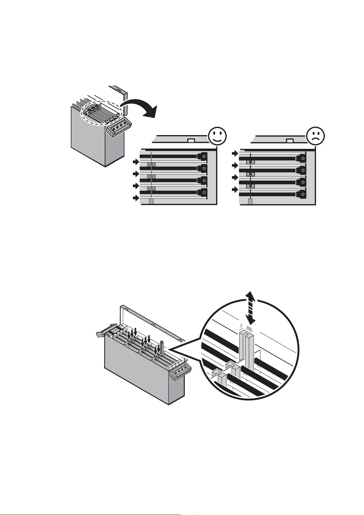
When removing panels from the flightcase, keep all protective material for use when repacking.
When repacking panels in the flightcase:
1. Insert panels with the clear LED tubes facing the front of the flightcase as shown in Figure 2, and
2. Insert the protective strips supplied with the flightcase so that the channel in each strip faces the front of
the flightcase and slides over the clear plastic brackets as shown in
Figure 3.
Front
Figure 3: Protective strip orientation
Important! When transporting a flightcase that is not full, pack panels from the front without leaving gaps,
so that any empty slots are at the back of the flightcase. Transport and store flightcases
standing in an upright position o nly. Do not transport flightcases lying flat on th eir si de.
Introduction 9
Page 10

Physical installation
Warning!Use two conical couplers to fasten a panel to a supporting structure or to another
panel – never use only one conical coupler. Secure with two approved safety cables, looping
one cable around each vertical side column. Do not use the LED tubes as secondary attachment
points.
When stacking panels one on top of another or suspending panels one from another, do not
exceed the limits given in Figure 4. If an installation needs to be taller than the limits gi ven in
Figure 4, additional support points must be provided to bear the weight of the additional panels.
The LC 1140/LC 2140 can be installed in a standing position alone or stacked, flown in a vertical curtain or
suspended in any orientation from a truss or supporting structu re.
LC 1140
LC 2140
Figure 4: Safety limits for stacking and suspending attached panels
Standing installation
Important! Do not place LC 1140/LC 2140 panels directly on a flat surface, as this will block the
flow of air to the air vents in the base and cause overheating.
Stacked
upright
Max. 10 Max. 9 Max. 9 Max. 9
Max. 8 Max. 6 Max. 7 Max. 7
Stacked
on side
Suspended
upright
Suspended
on side
See Figure 4. One vertical stack with LC 1140 panels resting on each other may contain a maximum of 10
LC 1140 panels stacked upright or 9 LC 1140 panels stacked on their sides.
One vertical stack with LC 2140 panels resting on each other may contain a maximum of 8 LC 2140 panels
stacked upright or 6 LC 2140 panels stacked on their sides.
An unlimited number of stacks of panels may be installed alongside each other.
If you install panels in a standing position:
1. Check that any structure or equipment used for support can bear at least 10 times the weight of all the
panels, clamps, cables, auxiliary equipment, etc. that will be placed on it.
2. Make sure that there will be at least 0.1 m (4 in.) of free space and unrestricted airflow to and around the
air vents in the base of the panels. One option is to install panels on stands or trusses placed on the
surface.
3. Check that there are no combustible materials within 0.5 m (20 in.) of the panels when installed, and that
there are no flammable materials nearby.
4. Fasten panels securely so that they cannot tip or fall.
10 LC 1140/LC 2140 user manual
Page 11

Flying from a truss, bar or other structure
See Figure 4. One vertical cur tain with LC 1140 panels suspended from each other may contain a
maximum of 9 panels. One vertical curtain with LC 2140 panels suspended from each other may contain a
maximum of 7 panels. These limits apply to panels both when suspended in an upright position and when
suspended on their sides.
An unlimited number of curtains of panels may be installed
alongside each other
To fly panels from a rig or other structure:
1. Check that the structure can bear at least 10 times the
weight of all the panels, clamps, cables, auxiliary equipment,
etc. that it will have to support.
2. See Figure 5. Check that the structure will not flex under the
weight of the panels. Hanging panels from a structure that is
not straight will place a strain on panels. Damage caused to
panels by mechanical stress is not covered by the product
warranty.
3. Check that there are no combustible materials within 0.5 m
(20 in.) of the panels when installed, and that there are no
flammable materials nearby.
4. Install two conical couplers in the top of the first panel and
install two rigging clamps or eyebolts on the couplers.
5. Block access under the work area. Working from a stable
platform, hang the panel by fastening the rigging clamps or
eyebolts to the truss or structure.
6. As soon as a panel is fastened in place, install two safety
cables to secure it. Safety attachments must be able to bear
at least 10 times the weight of all the panels they secure.
Loop safety cables in a figure-of-eight around vertical side
columns so that if a rigging clamp or conical connector fails,
the weight of the panels will be held by the vertical columns
and the blocks the columns are anchored in, and not by the
panel bases or top rails.
7. See Figure 6. Continue hanging panels, attaching them with
conical couplers (A) secured with threaded spigots (B) as illustrated. As soon as a panel is added to an
array, secure it with two safety attachments.
.
Figure 5: Avoidi ng stress on panels
B
B
A
B
A
B
Figure 6: Conical coupler system
Physical instal la tion 11
Page 12

Diffuser
280 280360
LC 1140: 900
15
480 440
LC 2140: 1900
A diffuser may be fastened to the panel,
respecting the diffuser manufacturer’s
safety precautions. Installing a diffuser
gives a softer rendition of the video
image, eliminating the ‘hot-spot’ effect.
Threaded holes for fastening a diffuser
front are provided next to the holes for
the conical coupler system. See Figure 7
for dimensions.
Single LED tubes
If you install panels angled away from
each other, you will be left with a gap in
the LED tubes at the apex of the angle.
To fill this gap and give a solid wall of
LEDs, it is possible to install a single
LED tube between two panels. This tube
must be connected to the Au x. Out
connector on the connections panel.
If you are interested in this solution,
contact your Martin supplier for details.
LC 1140: 900
LC 2140: 1900
Figure 7: Diffuser front mounting holes
12 LC 1140/LC 2140 user manual
Page 13

AC power
Warning! Read “Safety Information” on page 3 before connecting an LC 1140/LC 2140 panel to
AC power. Lock out power to the entire distribution system before carrying out installation work.
Important! Do not supply the panel with power via an external dimming system, or you may
cause damage to the panel that is not covered by the product warranty.
Power and main fuses
Warning! Replace fuses with ones of the same type and rating only.
The LC 1140/LC 2140 features an auto-sensing switch-mode power supply that automatically adapts to
100-120 V and 200-240 V nominal AC power at 50 or 60 Hz. Connect the panel to AC power that is within
these voltage ranges only.
Power circuits in both LC1140 and LC 2140 screens are protected by three 5 amp slow-blow main fuses
located on the three power PCBs in the base. See
and changing a main fuse.
Current fluctuation
Power and current figures are given in “Typical power and current” on page 32. Current draw fluctuates
slightly on a cycle of approximately one minute, especially at voltages over 200 V. Peak current draw is
unlikely to occur at exactly the same time in multiple fixtures, but to avoid unintentional tripping of
circuit-breakers, allow a safety margin of at least 20% when calculating the current requirements of an LC
1140/LC 2140 installation.
“Fuse replacement” on page 27 for details of accessing
Power connection
Warning! For protection from electric shock, the panel must be grounded (earthed). Power
distribution circuits must be fitted with a current overload fuse or circuit breaker and
ground-fault (earth-fault) protection.
Warning! The total current draw of all devices connected via one power input socket, including
the first panel connected, must not exceed 20
Warning! Use only a power cable that is listed, 12 AWG or 2.5 mm2, SJT (or better) and power
connectors that are listed, rated 20 A minimum.
Warning! The power socket/outlet must be installed near the LC 1140/LC 2140 and must be
easily accessible so that the LC 1140/LC 2140 can easily be disconnected from power if
necessary.
Powe r is supplied to the panel via the input socket. This socket accepts a blue Neutrik P o werCon NA C3FCA
cable connector.
Power can be relayed to another device via the output socket. This socket accepts a light-grey PowerCon
NAC3FCB cable connector. The total current drawn by devices that are interconnected by relaying power,
including the first panel, must not exceed 20 amps. This means that, with a safety margin of 20%, a
maximum of five LC 2140 panels or ten LC 1140 panels may be connected together at 230 V, for example.
Current draw figures for LC 1140/LC 2140 panels are given in
PowerCon connectors and suitable pow er cables with PowerCon connectors installed are available from
your Martin supplier.
amps.
“Typical power and current” on page 32.
AC power 13
Page 14

The Neutrik PowerCon NAC3FCA and NAC3FCB po wer cable connectors used with the LC 1140/LC 2140
accept power cable from 5 mm (0.20 in.) to 11 mm (0.43 in.) diameter when fitted with a white chuck, or
from 9.5 mm (0.4 in.) to 15 mm (0.6 in.) diameter when fitted with a black chuck.
ChuckInsertHousing
Bushing
Figure 8: PowerCon cable connector assembly
Content in these line drawings is cop yright ©2003 Neutrik A G and used b y permission. These illustrations ma y not be reprod uced in
any form without the written permission of Neutrik AG.
Figure 8 gives details of how to install a PowerCon connector on a power cable. Connect the live conductor
to the terminal marked L, the neutral conductor to the terminal marked N and the ground (earth) conductor
to the terminal marked .
You may need to fit your power cable with a pow er plug that is suitable for y our A C power outlets. If so , install
a grounding-type (earthed) plug that is rated 20 A minimum and follow the plug manufacturer’s instructions.
Wire Color Pin Symbol Screw (US)
brown live
blue neutral
yellow/green ground (earth) green
L
N
yellow or brass
silver
Table 1: Wire colors an d pin ide ntification
Table 1 shows common wire color codes and pin identification symbols. If pins are not clearly identified, or if
you have any doubts about proper installation, consult a qualified electrician .
To plug a PowerCon connector in, line up the raised tab on the cable connector with the keyway in the
chassis connector, push the cable connector in and twist clockwise to lock. To remove the connector, pull
back the latch to release the lock, twist the connector counterclockwise and pull out.
There is no power on/off switch on LC panels. Apply and shut down power using an external switch at the
power outlet or at the main switchboard. Make sure that the external switch is near the panels and easily
accessible so that power to the panels can easily be shut down if necessary. Do not power panels on or off
by inserting or removing live PowerCon connectors, as this will cause arcing at the connector contacts that
will damage devices and connectors.
Important! Shut down power to all panels and devices before connecting or disconnecting any element on
the video link, or you may damage your graphics card or other video components.
Shut down power to PowerCon connectors before inserting or removing them.
Apply power to the LC panels (and mo ni tor, if used) before you apply power to the media server,
or you may damage the panels’ video circuitry.
14 LC 1140/LC 2140 user manual
Page 15

Video link
LC Series panels accept a 1024 x 768 XGA DVI-D single link (digital
and DDC) signal and will display
2140) pixel image.
Each panel has two DVI connectors on its connections panel: one for
video input and one for video output. See Figure 9. Although the
video signal is DVI-D single link, the connectors are DVI-I dual link
type. The advantage of this solution is that any DVI cable can be
used, although only the pins that carry the DVI-D single link signal
are actually used.
An output labelled AUX is also provided for one extra LED tube that
can be added to fill the gap in a video cur tain if panels are installed
angled away from each other.
The LED labelled DVI on the connections panel lights when a valid
video signal is being received.
Planning the video link
Figure 10 and Figure 11 show examples of video link layout. The following elements are involved:
Media server: We recommend the use of the Martin Maxedia™ for its advanced features and intuitive user
interface.
a 25x25 (LC 1140) or 25x50 (LC
DVI-I dual link connector
DVI-D single link pins
Figure 9: DVI connectors
Important! The media server’s graphics card must be set to send a video signal with a 50 or 60 Hz refresh
rate, as LC 1140 and 2140 screens ac cept only these rates.
DVI buffer box: You need a buffer box on the link if the following functions are required:
1. 1024 x 768 DVI monitor emulation. The Maxed ia ‘expects to see’ a monitor on each of its outputs. The
DVI buffer box emulates a 1024 x 768 DVI monitor, allowing a Maxedia to operate correctly, and relays
the DVI signal to the rest of your installation.
2. Genlock synchronization of your installation via the buffer box’s BNC connector. The Martin DVI Buffer
Box also has a jumper that allows matching with a 50 or 60 Hz refresh rate.
3. Communication (reading installed software version, uploading new software, etc.) between the LC
Series management application running on a PC and video panels via the buffer box’s RS-232
connector. See “Advanced setup” on page 24 for the full list of functions.
DVI splitter: A splitter is required to send the video signal to more than one panel. It duplicates the video
signal and sends it to two or more DVI devices. Splitters aff ect the quality of the D VI signal so there are limits
to the number of devices that can be connected to successive generations (connecting a panel to a splitter
as shown in
Figure 11 creates a further generation).
Important! If a DVI splitter is used, the DDCCLOCK and DDCDATA signals on pins 6 and 7 of the DVI input
must be relayed to each of the splitter’s DVI outputs if you want a PC to communicate with the
panels connected to that output. Many DVI splitters relay the DDCCLOCK and DDCDATA signals
to only one output (typically Output 1). The Martin DVI splitters listed under
page 32 relay these signals to all outputs, ensuring that a PC can communicate with all the
panels on the video link.
Figure 10 gives a first generation signal, and connecting a splitter to a splitter as shown in
“Accessories” on
DVI monitor: A monitor is required to view the video image in parallel with the array of LC panels.
Important! The monitor must accept a DVI-D signal with a 50/60 Hz refresh rate.
Video link 15
Page 16

Figure 10 is a schematic diagram showing how to route the DVI video signal through one splitter with four
DVI outputs . Do not e xceed a maximum DVI cable length of 5 m (16.5 feet) between the splitter and the first
panel.
Media server
DVI monitor
DVI buffer box
Splitter
Figure 10: Schematic diagram of video connections
Sending the video signal through one splitter gives a first generation video signal. A maximum of 6 panels
can be connected to a first generation signal. If you have one splitter with 4 outputs on your video link, you
can therefore connect one monitor and 18 panels (or 12 panels with 2 monitors, 24 panels with no monitor,
etc.).
See Figure 11. If you want to connect more panels, you must connect y our monitor to the first output from
the first splitter and then connect more splitters to the first splitter’s other outputs. Sending a video signal
through two splitters gives a second generation video signal. A maximum of 5 panels can be connected to a
second generation signal. Sending a signal through a third splitter will give a third-generation signal, to
which you can connect a maximum of 4 panels, and so on.
16 LC 1140/LC 2140 user manual
Page 17

Figure 11 gives a schematic diagram of a link that contains a second level of splitters, giving a second
generation signal that allows a total of 60 panels to be connected.
Media server
DVI monitor
Splitter
DVI buffer box
Splitter
Splitter
Splitter
5 x LC
5 x LC 5 x LC
5 x LC 5 x LC
5 x LC
5 x LC 5 x LC
5 x LC
5 x LC
= Maximum five LC 1140 or 2140 panels
5 x LC 5 x LC
5 x LC
Figure 11: Second generation splitting
Connecting the video link
Important! Media server graphics cards, LC panel video circuits and other components on the video link
are sensitive and can easily be damaged by differences in potential. Observe the precautions
listed below, or you may cause damage that is not covered by the product warranty:
1. Shut down power to all panels and devices before connecting or disconnecting any
connector on the video link.
2. When inserting DVI connectors, ensure that the metal shields around the outside of male and
female connectors make contact before the pins. This will provide a path to ground (earth) for
any difference in potential between devices or components.
3. Apply power to the LC panels (and monitor, if used) before you apply power to the media
server.
4. When you shut down the entire installation, power the media server off before you cut power
to the LC panels and monitor.
To maintain signal quality, the DVI cable between any splitter and the first panel connected to it
must be maximum 5 m (16.5
feet) long.
To connect the video link:
1. Power all panels and devices off while making connections.
2. Connect the DVI output from the source (Martin Maxedia, for example) to a DVI buffer box.
3. Connect the DVI output from the DVI buffer box to the DVI input on a DVI splitter.
4. If you want to monitor the video image, connect the first DVI output from the splitter to your DVI monitor.
5. Connect the next DVI output from the splitter to either a second DVI splitter or the first panel’s DVI input
socket using a DVI cable max. 5 m (16.5 ft.) long.
6. Continue adding splitters or panels, connecting DVI output to DVI input and respecting the layout and
guidelines explained earlier in this section.
7. When you have made all connections, set up the panels as described in the next section of this man u al
before applying power first to the panels (and DVI monitor, if used) and then to the other devices.
Video link 17
Page 18

Panel setup
25pix
25pix
This section describes how to set panels to display a video image.
Video image resolution
Because LC 1140 panels can only display 25 x 25 pixels and LC 2140 panels can only display 25 x 50
pixels, to map every pixel in a 1024 x 768 pixel video image to a single pixel in a video curtain would require
a very large installation with 41 panels horizontally and either 31 LC 1140 or 16 LC 2140 panels vertically.
This arrangement would give full 1024 x 768 resolution with a few spare pixels at the edges.
Your installation probably has a smaller number of panels than this, so you can set up the output from your
media server in two ways:
• You can display an area of the video image that has the same number of pixels as your installation at full
pixel resolution (one pixel in the installation displays one pixel of the video image). The advantage of this
is that you do not lose any detail from this area of the image, but the disadvantage is that you can only
display part of the video image.
• You can display an area of the video image that has more pixels than your installation, but at reduced pixel
resolution (one pixel in the installation displays an “average” of more than one pixel in the video image).
The advantage of this is that you can display more of the video image than in the first method, but
because you only have a limited number of pixels in your installation, you must accept loss of detail from
the video image.
If you have a limited number of LC panels, you are thus faced with a trade-off between the amount of the
video image you display and the amount of detail that is possible: the more of the video image you display,
the less detail you can display. T o take an extreme example of this, it is possible to displa y a full 1024 x 768
video image on one LC panel, but you have to accept a very significant reduction in video image resolution
and loss of detail.
To reduce the resolution of a full 1024 x 768 video image, ‘shrink’ the image on your monitor screen until it
contains the same number of pixels as your installation. For example, to display a full 1024 x 768 video
image on an installation 200 pixels (8 panels) wide and 150 pixels (6 x LC 1140 panels or 3 x LC 2140
panels) high, you must ‘shrink’ the image to just under 20% of its original size, so that it fits in an area on
your monitor screen 200 pixels wide and 150 pixels high.
Note that LC panels cannot ‘shrink’ a video image themselves – ‘shrinking’ must be carried out on the media
server.
If your installation has the same aspect ratio as the video image (e.g. 1024 x 768, 800 x 600, 400 x 300, 200
x 150 pixels etc. for a 4:3 aspect ratio image), y ou can displa y the full video image using all the pixels in your
installation. However, the smaller your installation is, the more you must ‘shrink’ the video image, reducing
its resolution and thus the amount of detail you can display.
Tiles in the video image
The DVI signal on the video link contains the full video
image information everywhere on the link, so each
panel on the link receives the full video image. One
panel can display only a small part of the full image,
however, so each panel divides the video image into
x 25 pixel “tiles” as shown in Figure 12, and then
25
displays one or two tiles:
• an LC 1140 panel displays one tile
• an LC 2140 panel displays two tiles – one tile plus
the tile below it.
Setting panels to display tiles
To identify individual tiles, a panel gives each tile an x
and a y coordinate according to the following
principles:
• Coordinates are numbered starting at the top
left-hand corner of the video image when facing the
video image.
• The top left-hand tile is given the coordinates x = 0, y = 0.
• The next tile to the right is one tile further along the x axis, so it is given the coordinates x = 1, y = 0. After
this tile, the next tile to the right is assigned the coordinates x = 2, y = 0, and so on.
• The tile below the top left-hand tile is one tile furthe r down the y axis, so it is given the coordinates x = 0,
y = 1. The next tile down is assigned the coordinates x = 0, y = 2, and so on.
Figure 12: Tiles in the video image
18 LC 1140/LC 2140 user manual
Page 19

To set a panel to display a specific part of the video image, you set the x and y coordinates of the tile you
1-6
7-12
ON
OFF
12
1
ON
OFF
12
1
10 01111 0 0011 0 011
want it to display:
•An LC 1140 panel will display that 25 x 25 pixel tile
•An LC 2140 panel will display that 25 x 25 pixel tile plus the 25 x 25 pixel tile below it.
See Figure 13. Address setting is carried out on the panel’s DIP
switch. The DIP switch has 12 pins that are numbered from the
x coordinatey coordinate
right:
• Pins 1 to 6 are used to select the tile position on the x axis.
• Pins 7 to 12 are used to select the tile position on the y axis.
Numbers are set on DIP switches in binary form (1 = 000001,
2 = 000010, 3 = 000011, 4 = 000100, etc.). You set the
binary number for the x coordinate on pins 1 - 6 and set the binary
7-12
12
1-6
1
OFF
ON
number for the y coordinate on pins 7 - 12.
For example, to set the x coordinate 17 and the y coordinate 14 on
Figure 13: DIP switch functions
a DIP switch, you must first convert these coordinates to binary
numbers (17 =
010001, 14 = 001110), then set the dip switch
pins as shown in Figure 14.
12
1
1
OFF
ON
x coordinatey coordinate
PIN121110987654321
Setting OFF OFF ON ON ON OFF OFF ON OFF OFF OFF ON
001110010001
Figure 14: Example DIP switch settings
Video link 19
Page 20

Figure 15: Mapping LC 2140 and 1140 panels from the top left corner of the image
See Figure 15. The addressing principle for the y axis is slightly different for LC 2140 and LC 1140 panels
because they are different heights. Both types of panel are addressed starting with y = 0, but:
• setting the y coordinate to zero maps an LC 2140 panel to the top row (if you set DIP switch pins 7 - 12 to
0, the panel displays the rows with y coordinates 0 and 1), and
• setting the y coordinate to zero maps an LC 1140 panel to the second row (if you set DIP switch pins 7 12 to 0, the panel displays the row with y coordinate 1).
Note that an LC 1140 panel cannot be mapped to the top row of the video image.
If the principle behind mapping and addressing is confusing, just refer to the DIP switch settings shown in
Figure 15, Figure 17 and Figure 18, and set the addresses in your installation following these examples.
20 LC 1140/LC 2140 user manual
Page 21

Panel addressing – an example
20
14
21
15
Here is an example of how to set an array of panels so that each panel displays the correct ti le in the video
image. Let us say that:
• You have installed twenty-four LC 2140 panels in a curtain eight panels wide and three panels high, giving
you 200 x 150 pixels in your installation.
• You have ‘shrunk’ the image you want to display to 200 x 150 pixels on your monitor screen.
• You have positioned this 200 x 150 pixel image approximately in the center of your monitor (positioning in
the center of the monitor may not be absolutely necessary, but it usually gives more cropping and resizing
options in your media software).
You now need to set the addresses of your panels so that they display a block of 25 x 25 pixel tiles that is
= 8 tiles wide and 150/25 = 6 tiles high, positioned approximately in the center of the 1024 x 768
200/25
video image.
See Figure 16. In the full video signal, the x axis is approximately 41 tiles wide and the y axis is
approximately 32 tiles high. The tile with x coordinate 21 and y coordinate 16 is in the approximate center of
the video image.
15
16
Figure 16: Finding the approximate center of the video display
Video link 21
Page 22

See Figure 17. To address the LC 2140 panels in your installation so that they display the 200 x 150 pixel
block in the center of your monitor, you must give them the x and y coordinates shown in the illustration.
Figure 17: Displaying tiles in center of video image (LC 2140)
22 LC 1140/LC 2140 user manual
Page 23

If LC 1140 panels are used to display the same pixels from the video image, they must be set as shown in
17
16
15
14
18
19
18
19
20
21
22
23
24
17
Y= 16 X = 17
Y= 16 X = 18
Y= 16 X = 19
Y= 16 X = 20
Y= 14 X = 17
Y= 14 X = 18
Y= 14 X = 19
Y= 14 X = 20
Y= 15 X = 17
Y= 15 X = 18
Y= 15 X = 19
Y= 15 X = 20
Y= 17 X = 17
Y= 17 X = 18
Y= 17 X = 19
Y= 17 X = 20
Y= 18 X = 17
Y= 18 X = 18
Y= 18 X = 19
Y= 18 X = 20
Y= 13 X = 17
Y= 13 X = 18
Y= 13 X = 19
Y= 13 X = 20
Y= 17 X = 21
Y= 17 X = 22
Y= 17 X = 23
Y= 17 X = 24
Y= 18 X = 21
Y= 18 X = 22
Y= 18 X = 23
Y= 18 X = 24
Y= 13 X = 21
Y= 13 X = 22
Y= 13 X = 23
Y= 13 X = 24
Y= 14 X = 21
Y= 14 X = 22
Y= 14 X = 23
Y= 14 X = 24
Y= 15 X = 21
Y= 15 X = 22
Y= 15 X = 23
Y= 15 X = 24
Y= 16 X = 21
Y= 16 X = 22
Y= 16 X = 23
Y= 16 X = 24
001 111 - 010001
001 111 - 010010
001 111 - 01001 1
001111 - 0101 00
010000 - 010001
010000 - 010010
010000 - 010011
010000 - 010100
010001 - 010001
010001 - 010010
010001 - 010011
010001 - 010100
010010 - 010001
01001 0 - 01001 0
01001 0 - 010011
01001 0 - 010100
001 101 - 010001
001101 - 010010
001101 - 010011
001101 - 010100
001 110 - 010001
001 110 - 010010
001 110 - 010011
001110 - 01 01 00
01001 0 - 0101 01
01001 0 - 010110
01001 0 - 010111
01001 0 - 011000
001101 - 010101
001101 - 010110
001101 - 010111
001101 - 011000
001110 - 01 01 01
001110 - 01 011 0
001110 - 01 0111
001110 - 0110 00
001111 - 0101 01
001111 - 01011 0
001111 - 01 0111
001 111 - 01 1000
010000 - 010101
010000 - 010110
010000 - 01011 1
010000 - 011000
010001 - 010101
010001 01 011 0
010001 - 010111
010001 - 011000
Figure 18.
Note that with LC 1140 panels, you must set the y coordinate to the number of the row on the y axis minus
one (i.e. to locate an LC 1140 panel on row 16 of the y axis, you must set its y coordinate to 15).
14
15
16
17
18
17
Y = 13 X = 17
001101 - 010001
Y = 14 X = 17
001110 - 010001
Y = 15 X = 17
001111 - 010001
Y = 16 X = 17
010000 - 010001
Y = 17 X = 17
010001 - 010001
18
Y = 13 X = 18
001101- 010010
Y = 14 X = 18
001110 - 010010
Y = 15 X = 18
001111 - 010010
Y = 16 X = 18
010000 - 010010
Y = 17 X = 18
010001 - 010010
19
Y = 13 X = 19
001101- 010011
Y = 14 X = 19
001110 - 010011
Y = 15 X = 19
001111 - 010011
Y = 16 X = 19
010000 - 010011
Y = 17 X = 19
010001 - 010011
20
Y = 13 X = 20
001101- 010100
Y = 14 X = 20
001110 - 010100
Y = 15 X = 20
001111 - 010100
Y = 16 X = 20
010000 - 010100
Y = 17 X = 20
010001 - 010100
21
Y = 13 X = 21
001101- 010101
Y = 14 X = 21
001110 - 010101
Y = 15 X = 21
001111 - 010101
Y = 16 X = 21
010000 - 010101
Y = 17 X = 21
010001 - 010101
22
Y = 13 X = 22
001101- 010110
Y = 14 X = 22
001110 - 010110
Y = 15 X = 22
001111 - 010110
Y = 16 X = 22
010000 - 010110
Y = 17 X = 22
010001 010110
23
Y = 13 X = 23
001101- 010111
Y = 14 X = 23
001110 - 010111
Y = 15 X = 23
001111 - 010111
Y = 16 X = 23
010000 - 010111
Y = 17 X = 23
010001 - 010111
24
Y = 13 X = 24
001101- 011000
Y = 14 X = 24
001110 - 011000
Y = 15 X = 24
001111 - 011000
Y = 16 X = 24
010000 - 011000
Y = 17 X = 24
010001 - 011000
19
Y = 18 X = 17
010010 - 010001
Y = 18 X = 18
010010 - 010010
Y = 18 X = 19
010010 - 010011
Y = 18 X = 20
010010 - 010100
Y = 18 X = 21
010010 - 010101
Y = 18 X = 22
010010 - 010110
Figure 18: Displaying tiles from center of video image (LC 1140)
Video link 23
Y = 18 X = 23
010010 - 010111
Y = 18 X = 24
010010 - 011000
Page 24

Tips for panel addressing
You may find the following tips helpful when setting addresses on panels:
• Remember that if you have LC 2140 panels in your installation, you must set y coordinate addresses to
14, 16 and 18 to obtain a correct video image.
• As mentioned earlier, when setting the y coordinate of an LC 1140 panel, remember that you must
subtract 1 from the row on the y axis where you want to locate that panel (for example, set the y
coordinate on an LC 1140 panel’s DIP switch to 15 if you want that panel to display a tile on row 16 on the
y axis.
• If you are mixing LC 2140 and LC 1140 panels in an installation, bear in mind that LC 1140 panels cannot
be set to display the top row (row with y coordinate zero) in the video image – this row can only be
displayed with LC 2140 panels.
• You can save time converting decimal to binary numbers by using one of the many free converters
available on the Internet.
• After setting the addresses of the panels in an installation, you may need to do a little fine adjustment to
the position of the pixel image on your monitor to align it precisely with your group of panels.
Advanced setup
Using the Martin LC Series DVI Buffer Box (P/N 91611269) and a PC with the LC Series management
application (included with the buffer box), the following operations can be carried out via the video link:
• Viewing the software version currently installed in each panel in an installation.
• Uploading new software to panels in an installation.
• Genlock via the buffer box’s BNC connector
• Brightness adjustment for an individual panel
• Global brightness adjustment for a complete installation
• Video image freeze-frame from the PC application
Full details and instructions covering these operations are included with the DVI buffer box.
24 LC 1140/LC 2140 user manual
Page 25

Operation
If the system is correctly set up, operation is simply a question of displaying video from the media server or
other DVI video source.
During operation, four LED indicators on the connections panel give information about the status of the
panel and the video signal:
• The Power LED lights when power is applied to the panel.
• The Pulse LED flashes when the system controller is running. The flash rate is 1/16 of the signal
frequency (at 50 Hz, 20 flashes take approx. 12 seconds). The LED flashes slowly when there is no
signal.
• The Error LED should not light during normal operation. It lights constantly if there is a fault in the video
signal or panel. The Error LED has a secondary function: it flashes when there is communication
between a PC and the panel.
• The DVI LED lights when the panel is receiving a valid DVI signal.
When repacking panels in a Martin flightcase after operation, follow carefully the instructions in “Packing
panels in the flightcase” on page 9.
Operation 25
Page 26

Service and maintenance
Warning! Read “Safety Information” on page 3 before carrying out service or maintenance work
on the LC 1140/LC 2140. Lock out power to the entire distribution system before servicing,
cleaning or removing any cover. Refer any service operation not described here to a
qualified service technician.
Important! Excessive dust, smok e fluid, and par ticle buildup degrades performance, causes
overheating and will damage the panel. Damage caused by inadequate cleaning or maintenance
is not covered by the product warranty.
As with electronic components in general, the LC 1140/LC 2140’s PCBs are sensitive to ESD
(electrostatic discharge). Take precautions to avoid ESD damage during service.
It is Martin policy to use the best quality materials available to ensure optimum performance and the longest
possible component lifetimes. However, optical components in all lighting fixtures are subject to wear and
tear over the life of the fixture, resulting in gradual changes in color rendition, for example.
The extent of wear and tear depends heavily on operating conditions, maintenance and environment, so it is
impossible to specify precise lifetimes for optical components. However, you will eventually need to replace
the LEDs in the LC 1140/LC 2140 if their characteristics are affected by wear and tear after an extended
period of use and if you require panels to perform within very precise optical and color parameters.
To maximize the life of the LC 1140/LC 2140 and protect the investment it represents, clean the panel
regularly – especially the cooling fans and grilles – following the guidelines in this section.
Cleaning
Regular cleaning is essential for product life and performance. Buildup of dust, dirt, smoke particles, fog
fluid residues, etc. degrades the panel’s light output and cooling ability.
Cleaning schedules for lighting fixtures vary greatly depending on the operating environment. It is therefore
impossible to specify precise cleaning intervals for the LC 1140/LC 2140. Cooling fans suck in airborne dust
and smoke particles, and in extreme cases panels may require cleaning after surprisingly few hours of
operation. Environmental factors that may result in a need for frequent cleaning include:
• Use of smoke or fog machines.
• High airflow rates (near air conditioning vents, for example).
• Presence of cigarette smoke.
• Airborne dust (from stage effects, building structures and fittings or the natural environment at outdoor
events, for example).
If one or more of these factors is present, inspect panels within their first 25 hours of operation to see
whether cleaning is necessary. Check again at frequent intervals. This procedure will allow you to assess
cleaning requirements in your particular situation. If in doubt, consult your Martin dealer about a suitable
maintenance schedule.
Do not use abrasive, caustic or solvent-based products for cleaning, as they can damage plastic or painted
surfaces.
To clean the panel:
1. Disconnect the panel from power and allow it to cool for at least 10 minutes.
2. Vacuum or gently blow away dust and loose particles from the fan blades and grilles in the base of the
panel with compressed air.
3. Wipe the outside of the LED tubes with a soft, lint-free cloth dampened with a solution of water and
detergent or auto shampoo. Apply gentle pressure only.
If the inside surfaces of the LED tubes require cleaning, remove the tubes, slide the LED circuit boards out
of each tube as described in “Replacing LED tubes” on page 28, and blow through with compressed air. If
necessary, flush each tube with a warm water/detergent solution. Dry thorough ly with compressed air
before reassembling.
26 LC 1140/LC 2140 user manual
Page 27

Fuse replacement
Torx 10
Warning! Disconnect from power before opening covers. Replace fuses with ones of the same
type and rating only.
Important! The PCBs are sensitive to ESD (electrostatic discharge). Take precautions to avoid
ESD damage. Avoid touching electronic components.
LC 1140 and LC 2140 panels are protected by three 5 amp slow-blow fuses on the three power supplies in
the panel base.
To replace a fuse:
1. Disconnect the panel from power and allow to cool for 10 minutes.
2. See Figure 19. Remove four screws (arro wed) from a base co v er and lift the cov er up slightly for access
to the fuse. Avoid pulling hard on covers, as this will strain the wiring.
Torx 10
Figure 19: Fuse replacement
3. Replace the defective fuse with one of the same type and rating only . Replacement fuses are av ailable
from Martin suppliers.
4. Reinstall the cover before reapplying power.
Service and maintenance 27
Page 28

Replacing LED tubes
A
B
C
D
E
F
To replace an LED tube:
1. Disconnect the panel from power and allow to
cool for 10 minutes.
2. See Figure 20. Insert a broad flat-blade
screwdriver into the slot in each of the clear
plastic brackets immediately behind the tube
you want to remove. Twist the screwdriver very
slightly to release the tube in the slot so that it
can be pulled forward out of the bracket.
3. See Figure 21. When the tube is released from
all brackets, bend it outwards at the center (A
and B) until the top of the tube is clear of the
retaining bracket (C).
4. Pull the top of the tube forward (D) just enough
for the tube to clear the retaining bracket. Do not
pull the tube further forward than is necessary.
5. Lift the tube upwards (E), holding the PCB at
the bottom of the tube so that it is unplugged
from the base as the tube is l ifted (F). Be carefu l
not to damage the connector terminals on the
PCBs while handling.
6. Slide the PCBs out of the tube for access to the LEDs.
Figure 20: Releasing an LED tube
C
E
Figure 21: Removing an LED tube
F
D
To install an LED tube:
1. Hold the tube up against the panel. Plug the PCB at the bottom of the tube carefully into the panel base,
avoiding any pressure that might damage the terminals.
2. Bend the center of each tube outwards as shown at (A) in Figure 21 until the top of the tube can pass
28 LC 1140/LC 2140 user manual
under the retaining bracket (C). Slide the top of the tube under the retaining bracket.
3. Allow the tube to straighten so that the top of the tube engages in its cutout in the retaining bracket.
4. Clip the tube into the clear plastic brackets.
5. Do not reapply power until all tubes have been installed.
Page 29

Installing new software
It may be necessary to upload new software to the LC 1140/LC 2140 if the product appears to have a
software-related fault or if you want to update to a newer software v ersion. Software updates are available
from Martin and can be installed via the video link.
The following items are required in order to update software:
• The LC 1140/LC 2140 main CPU software update file, downloadable free of charge from the Support area
of the Martin website at http://www.martin.com
• A Martin LC Series DVI Buffer Box (P/N 91611269) and PC with the LC management application that is
included with the DVI buffer box.
Instructions for uploading new software are included with the DV I buffer box.
Service and maintenance 29
Page 30

Troubleshooting
Problem Probable cause(s) Remedy
No power to panel. Check power and connections.
Panel is completely dead.
One or more panels displays
video incorrectly or does not
display video at all.
All LC panels and/or monitor
screen display video incorrectly
or do not display video at all.
Display cuts out intermittently. Panel is too hot.
Error LED lights continuously. Fault in video signal or panel.
Error LED flashes while a PC is
connected.
Fuse blown (located on PCBs behind
connections panel).
Fault on video link.
Incorrect panel addressing. Check addressing on panel.
Panel defective.
Device on video link defective.
Media server not sending at 50 or 60 Hz
refresh rate.
Fault on video link.
Device on video link defective.
No action is needed, this is normal.
Disconnect panel from power. Check fuses and
replace.
Inspect connections and cables. Correct poor
connections. Repair or replace damaged cables.
Have faulty panel serviced by Martin service
technician.
Have faulty panel tested and serviced by Martin
service technician or supplier.
Adjust media server/graphic card settings.
Inspect connections and cables. Correct poor
connections. Repair or replace damaged cables.
Have faulty panel tested and serviced by Martin
service technician or supplier.
Ensure free airflow around air vents.
Clean fans and vents.
Check that ambient temperature does not exceed
max. permitted level.
Contact Martin for service.
Check all video connections, cables and
equipment.
Reset panel by disconnecting from power, then
reconnecting.
If Error LED continues to light, contact Martin for
service.
Table 2: Troubleshooting
30 LC 1140/LC 2140 user manual
Page 31

Specifications
Physical
Length . . . . . . . . . . . . . . . . . . . . . . . . . . . . . . . . . . . . . . . . . . . . . . . . . . . . . . . . . . . . . . .1000 mm (39.4 in.)
Width . . . . . . . . . . . . . . . . . . . . . . . . . . . . . . . . . . . . . . . . . . . . . . . . . . . . . . . . . . . . . . . . . .110 mm (4.3 in.)
Height, LC 1140. . . . . . . . . . . . . . . . . . . . . . . . . . . . . . . . . . . . . . . . . . . . . . . . . . . . . . . .1004 mm (39.5 in.)
Height, LC 2140. . . . . . . . . . . . . . . . . . . . . . . . . . . . . . . . . . . . . . . . . . . . . . . . . . . . . . . .2004 mm (78.9 in.)
Weight, LC 1140 . . . . . . . . . . . . . . . . . . . . . . . . . . . . . . . . . . . . . . . . . . . . . . . . . . . . . . . 14.3 kg (31.5 lbs.)
Weight, LC 2140 . . . . . . . . . . . . . . . . . . . . . . . . . . . . . . . . . . . . . . . . . . . . . . . . . . . . . . . 19.4 kg (42.8 lbs.)
Control and Programming
Setting and addressing . . . . . . . . . . . . . . . . . . . . . . . . . . . . . . . . . . . . . . . . . . . . . . . . . . . . . . . . DIP switch
Video Processing
Video signal processor . . . . . . . . . . . . . . . . . . . . . . . . . . . . . . . . . . . . . . . . . . . . . . . . . . . . . . . . .Integrated
Video signal. . . . . . . . . . . . . . . . . . . . . . . . . XGA 1024 x 768 DVI-D (digital single link), 25 x 25 (LC 1140)
Video signal frequency . . . . . . . . . . . . . . . . . . . . . . . . . . . . . . . . . . . . . . . . . . . . . . . . . . . . . . . 50 or 60 Hz
Genlock . . . . . . . . . . . . . . . . . . . . . . . . . . . . . . . . . . . . . . . . . . . . . . . . . . . . .Yes (via Martin DVI b u f fer box)
Photometric Data
Light source. . . . . . . . . . . . . . . . . . . . . . . . . . . . . . . . . . . . . . . . . . . . . . . . . . . . . . .5 mm (0.2 in.) oval LED
Total output (max.) . . . . . . . . . . . . 1800 Cd/m2 (1800 nits) measured outside LED tubes, Ta 25° C (77° F)
Pitch (pixel center-to-center) . . . . . . . . . . . . . . . . . . . . . . . . . . . . . . . . . . . . . . . . . . . . . . . . .40 mm (1.6 in.)
Pixels per m2 . . . . . . . . . . . . . . . . . . . . . . . . . . . . . . . . . . . . . . . . . . . . . . . . . . . . . . . . . . . . . . . . . . . . . .625
Red dominant wavelength . . . . . . . . . . . . . . . . . . . . . . . . . . . . . . . . . . . . . . . . . . . . . . . .627.5 nm ± 2.5 nm
Green dominant wavelength . . . . . . . . . . . . . . . . . . . . . . . . . . . . . . . . . . . . . . . . . . . . . .522.5 nm ± 2.5 nm
Blue dominant wavelength. . . . . . . . . . . . . . . . . . . . . . . . . . . . . . . . . . . . . . . . . . . . . . . .472.5 nm ± 2.5 nm
Color resolution . . . . . . . . . . . . . . . . . . . . . . . . . . . . . . . . . . . . . . . . . . . . . . . . . . . . . . . . . . 14 bits per color
Viewing angle. . . . . . . . . . . . . . . . . . . . . . . . . . . . . . . . . . . >100° horizontal, >40° vertical at 50% intensity
or 25 x 50 (LC 2140) pixels displayed
LC 1140
Resolution, one panel . . . . . . . . . . . . . . . . . . . . . . . . . . . . . . . . . . . . . . . . . . . . . . . . . . . . . . .25 x 25 pixels
Pixels per panel. . . . . . . . . . . . . . . . . . . . . . . . . . . . . . . . . . . . . . . . . . . . . . . . . . . . . . . . . . . . . . . . . . . .625
LEDs per panel . . . . . . . . . . . . . . . . . . . . . . . . . . . . . . . . . . . . . . . . . . . . . . . . . . . . . . . . . . . . . . . . . . .1875
LC 2140
Resolution, LC 2140, one panel . . . . . . . . . . . . . . . . . . . . . . . . . . . . . . . . . . . . . . . . . . . . . . .25 x 50 pixels
Pixels per panel. . . . . . . . . . . . . . . . . . . . . . . . . . . . . . . . . . . . . . . . . . . . . . . . . . . . . . . . . . . . . . . . . . .1250
LEDs per panel . . . . . . . . . . . . . . . . . . . . . . . . . . . . . . . . . . . . . . . . . . . . . . . . . . . . . . . . . . . . . . . . . . .3750
Construction
Panel frames . . . . . . . . . . . . . . . . . . . . . . . . . . . . . . . . . . . . . . . . . . . . . . . . . . . . . . . . .Steel and aluminum
LED tubes . . . . . . . . . . . . . . . . . . . . . . . . . . . . . . . . . . . . . . . . . . . . . . . . . . . . . . . . . . . . . . . . . . . . . Acrylic
LED tubes per panel . . . . . . . . . . . . . . . . . . . . . . . . . . . . . . . . . . . . . . . . . . . . . . . . . . . . . . . . . . . . . . . . .25
Transparency through LED tubes (unmasked area) . . . . . . . . . . . . . . . . . . . . . . . . . . . . . . . . . . . . . .> 60%
Color . . . . . . . . . . . . . . . . . . . . . . . . . . . . . . . . . . . . . . . . . . . . . . . . . . . . . . . . . . . . . . . Black panel frames
Protection rating. . . . . . . . . . . . . . . . . . . . . . . . . . . . . . . . . . . . . . . . . . . . . . . . . . . . . . . . . . . . . . . . . . .IP 20
Installation
Orientation. . . . . . . . . . . . . . . . . . . . . . . . . . . . . . . . . . . . . . . . . . . . . . . . . . . . . . . . . . . . . . . . . . . . . . . .Any
Panel combination. . . . . . . . . . . . . . . . . . . . . . . . . . . . . . . . . . .Up to 7 hung vertically, no limit horizontally
Panel interlocking. . . . . . . . . . . . . . . . . . . . . . . . . . . . . . . . . . . . . . . . Prolyte CCS6 conical coupler system
Connections
Power in/out. . . . . . . . . . . . . . . . . . . . . . . . . . . . . . . . . . . . . . . . . . . . . . . . . . . . . . . . . . . Neutrik PowerCon
Video in/out . . . . . . . . . . . . . . . . . . . . . . . . . . . . . . . DVI-D single link (DVI-I dual link connecto rs provided)
Specifications 31
Page 32

Electrical
AC power. . . . . . . . . . . . . . . . . . . . . . . . . . . . . . . . . . . . . . . . . . . . . 100-120/200-240 V nominal, 50/60 Hz
Power supply unit. . . . . . . . . . . . . . . . . . . . . . . . . . . . . . . . . . . . . . . .Integrated, auto-sensing multi-voltage
Main fuses . . . . . . . . . . . . . . . . . . . . . . . . . . . . . . . . . . . . . . . . . . . . . . . . .3 x 5 AT (LC 1140 and LC 2140)
Typical power and current
LC 1140
100 V, 50 Hz. . . . . . . . . . . . . . . . . . . . . . . . . . . . . . . . . . . . . . . . . . . . . . . . . . . . . .310 W, 3.2 A, PF = 0.988
100 V, 60 Hz. . . . . . . . . . . . . . . . . . . . . . . . . . . . . . . . . . . . . . . . . . . . . . . . . . . . . .309 W, 3.2 A, PF = 0.989
127 V, 50 Hz. . . . . . . . . . . . . . . . . . . . . . . . . . . . . . . . . . . . . . . . . . . . . . . . . . . . . .305 W, 2.5 A, PF = 0.974
200 V, 50 Hz. . . . . . . . . . . . . . . . . . . . . . . . . . . . . . . . . . . . . . . . . . . . . . . . . . . . . .299 W, 1.6 A, PF = 0.978
240 V, 50 Hz. . . . . . . . . . . . . . . . . . . . . . . . . . . . . . . . . . . . . . . . . . . . . . . . . . . . . .291 W, 1.6 A, PF = 0.820
LC 2140
100 V, 50 Hz. . . . . . . . . . . . . . . . . . . . . . . . . . . . . . . . . . . . . . . . . . . . . . . . . . . . . .627 W, 6.4 A, PF = 0.995
100 V, 60 Hz. . . . . . . . . . . . . . . . . . . . . . . . . . . . . . . . . . . . . . . . . . . . . . . . . . . . . .627 W, 6.3 A, PF = 0.995
127 V, 50 Hz. . . . . . . . . . . . . . . . . . . . . . . . . . . . . . . . . . . . . . . . . . . . . . . . . . . . . .612 W, 4.9 A, PF = 0.987
200 V, 50 Hz. . . . . . . . . . . . . . . . . . . . . . . . . . . . . . . . . . . . . . . . . . . . . . . . . . . . . .590 W, 3.1 A, PF = 0.964
240 V, 50 Hz. . . . . . . . . . . . . . . . . . . . . . . . . . . . . . . . . . . . . . . . . . . . . . . . . . . . . .584 W, 2.8 A, PF = 0.875
Figures apply with all LEDs at max. intensity . Figures are valid at nominal vo ltage and are typical averages ,
not maximum. Current draw may fluctuate at approx. 1 cycle per minute, especially at 200 V and above.
Current fluctuation will not occur at the same cycle in all panels, but to avoid unintentional tripping of circuit
breakers, add a 20% safety margin when calculating the current capacity of the power distrib ution syste m.
Thermal
Cooling. . . . . . . . . . . . . . . . . . . . . . . . . . . . . . . . . . . . . . . . . .Forced air (temperature-regulated, low noise)
Maximum ambient temperature (Ta max.) . . . . . . . . . . . . . . . . . . . . . . . . . . . . . . . . . . . . . . . 40° C (104° F)
Minimum ambient temperature (Ta min.) . . . . . . . . . . . . . . . . . . . . . . . . . . . . . . . . . . . . . . . . . . 0° C (32° F)
Total heat dissipation LC 1140 (calculated, 200 V, 50 Hz / 100 V, 60 Hz) . . . . . . . . . . 1020 / 1060 BTU/hr.
Total heat dissipation LC 2140 (calculated, 200 V, 50 Hz / 100 V, 60 Hz) . . . . . . . . . . .2020 / 2140 BTU/hr.
Acoustic
Noise level. . . . . . . . . . . . . . . . . . . . < 45 dBA for one panel at 1 m (3.3 ft.), steady state, Ta 25° C (77° F)
Approvals
EU safety. . . . . . . . . . . . . . . . . . . . . . . . . . . . . . . . . . EN 60825-1, EN 60950
EU EMC. . . . . . . . . . . . EN 55022, EN 55024, EN 61000-3-2, EN 61000-3-3
US safety. . . . . . . . . . . . . . . . . . . . . . . . . . . . . . . . . . . . . . .ANSI/UL 60950-1
Canadian safety. . . . . . . . . . . . . . . . . . . . . . . . . . . . . . CAN/CSA 60950-1-03
Included Items
Prolyte CCS6 conical couplers and threaded spigots
User manual . . . . . . . . . . . . . . . . . . . . . . . . . . . . . . . . . . . . . . . . . . . . . . . . . . . . . . . . . . . . . P/N 35000196
Accessories
3 m (9.8 ft.) power cable with Neutrik PowerCon NAC3FCA power input connector. . . . . . . P/N 11541503
Neutrik PowerCon NAC3FCA power input connector, cable mount, blue . . . . . . . . . . . . . . . P/N 05342804
Neutrik PowerCon NAC3FCB power output connector, cable mount, light grey . . . . . . . . . . P/N 05342805
PowerCon daisy-chain power cable, 1.4 m (55 in.) . . . . . . . . . . . . . . . . . . . . . . . . . . . . . . . . P/N 11850099
PowerCon daisy-chain power cable, 2.25 m (89 in.) . . . . . . . . . . . . . . . . . . . . . . . . . . . . . . . P/N 11850100
PowerCon daisy-chain power cable, 3.25 m (128 in.) . . . . . . . . . . . . . . . . . . . . . . . . . . . . . . P/N 11850101
DVI-D cable, 1.5 m (59 in.). . . . . . . . . . . . . . . . . . . . . . . . . . . . . . . . . . . . . . . . . . . . . . . . . . . P/N 91611265
DVI-D cable, 3.2 m (126 in.). . . . . . . . . . . . . . . . . . . . . . . . . . . . . . . . . . . . . . . . . . . . . . . . . . P/N 91611266
DVI-D cable, 5 m (197 in.) . . . . . . . . . . . . . . . . . . . . . . . . . . . . . . . . . . . . . . . . . . . . . . . . . . . P/N 91611267
Martin DVI buffer box, LC Series . . . . . . . . . . . . . . . . . . . . . . . . . . . . . . . . . . . . . . . . . . . . . . P/N 91611269
Martin DVI splitter, 2-output . . . . . . . . . . . . . . . . . . . . . . . . . . . . . . . . . . . . . . . . . . . . . . . . . . P/N 91611280
Martin DVI splitter, 4-output . . . . . . . . . . . . . . . . . . . . . . . . . . . . . . . . . . . . . . . . . . . . . . . . . . P/N 91611290
Martin DVI splitter, 8-output . . . . . . . . . . . . . . . . . . . . . . . . . . . . . . . . . . . . . . . . . . . . . . . . . . P/N 91611281
Prolyte CCS6 conical coupler . . . . . . . . . . . . . . . . . . . . . . . . . . . . . . . . . . . . . . . . . . . . . . . . P/N 21021150
Threaded spigot for conical coupler. . . . . . . . . . . . . . . . . . . . . . . . . . . . . . . . . . . . . . . . . . . . P/N 08330125
Half conical coupler (used as floor-mounting option). . . . . . . . . . . . . . . . . . . . . . . . . . . . . . . P/N 26820300
Four-unit flightcase for 4 x LC 1140. . . . . . . . . . . . . . . . . . . . . . . . . . . . . . . . . . . . . . . . . . . . P/N 91510110
Four-unit flightcase for 4 x LC 2140. . . . . . . . . . . . . . . . . . . . . . . . . . . . . . . . . . . . . . . . . . . . P/N 91510040
32 LC 1140/LC 2140 user manual
Page 33

Related Products
Martin Maxedia PRO™ System Media Server, EU . . . . . . . . . . . . . . . . . . . . . . . . . . . . . . . . P/N 90732520
Martin Maxedia PRO™ System Media Server, US . . . . . . . . . . . . . . . . . . . . . . . . . . . . . . . . P/N 90732530
Martin Maxedia Compact™ System Media Server, EU/US . . . . . . . . . . . . . . . . . . . . . . . . . . P/N 90732540
Ordering Information
4 x Martin LC 2140™, 2 x 1 m, in 4-unit flightcase with 16 couplers and 24 spigo ts. . . . . . . P/N 90 354100
4 x Martin LC 1140™, 1 x 1 m, in 4-unit flightcase with 16 couplers and 24 spigots. . . . . . . P/N 90354110
Martin LC 2140™, 2 x 1 m, in cardboard box with 4 couplers and 6 spigots. . . . . . . . . . . . . P/N 90354120
Martin LC 1140™, 1 x 1 m, in cardboard box with 4 couplers and 6 spigots. . . . . . . . . . . . . P/N 90354130
Specifications subject to change without notice
Specifications 33
Page 34

Notes
Page 35

Page 36

 Loading...