

Page 1

user manual
P/N 35010042-D
READ AND SAVE THESE INSTRUCTIONS
Page 2
2
Dimensions/Legal
Dimensions/Legal
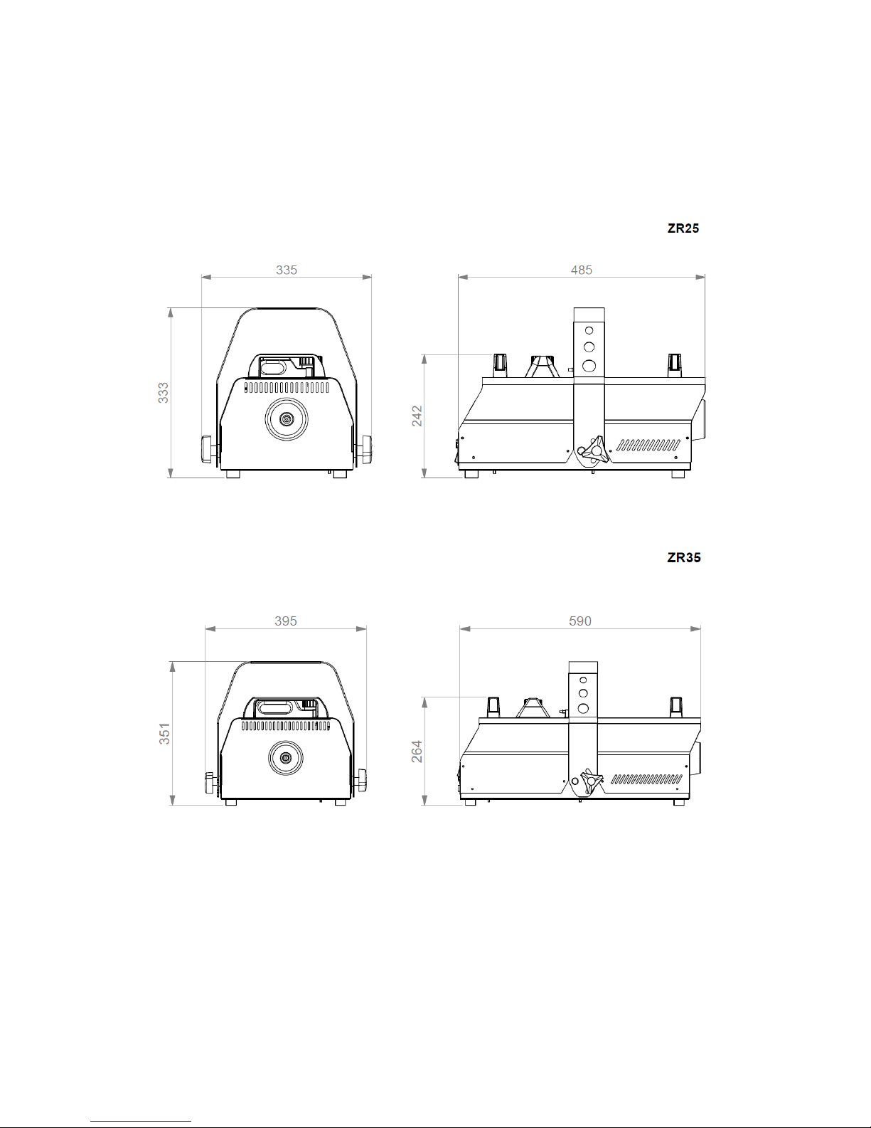
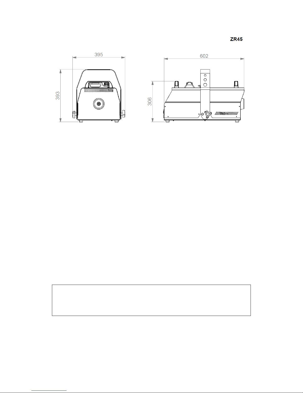
All dimensions are in millimeters
™
™
Page 3
3
© 2016 Martin Professional™ ApS. Information subject to change without notice. Martin Professional and all
affiliated companies disclaim liability for any injury, damage, direct or indirect loss, consequential or economic loss or
any other loss occasioned by the use of, inability to use or reliance on the information contained in this manual.
Martin™, Harman™ and all other trademarks in this document pertaining to services or products by Martin
Professional or its affiliates and subsidiaries are registered as the property of Harman International Industries.
Martin Professional™ ApS • Olof Palmes Allé 18 • 8200 Aarhus N • Denmark • www.martin.com
™
Page 4

4
Contents
Contents
Dimensions/Legal ...................................................................................................................... 2
Contents .................................................................................................................................... 4
Safety information ...................................................................................................................... 5
Product overview ....................................................................................................................... 8
Product description ................................................................................................................ 8
Features at a glance .............................................................................................................. 8
Product details ....................................................................................................................... 9
Quick Start ............................................................................................................................... 12
Setting up ............................................................................................................................. 12
Making fog ........................................................................................................................... 12
Installation and Setting Up ...................................................................................................... 13
Location ............................................................................................................................... 13
AC power ............................................................................................................................. 13
Setting up ............................................................................................................................. 14
Final checks ......................................................................................................................... 14
Turning on the power ........................................................................................................... 14
Control Settings ....................................................................................................................... 15
Overview .............................................................................................................................. 15
Setting Run modes .............................................................................................................. 15
Setting Fog output density ................................................................................................... 15
Setting the Timer .................................................................................................................. 16
Using the Settings menu...................................................................................................... 16
Setting the DMX base address ............................................................................................ 16
Display back light setting ..................................................................................................... 16
Setting the master-slave link mode...................................................................................... 16
Priming the machine after fluid out ...................................................................................... 17
Resetting options to factory settings ................................................................................... 17
DMX Control ............................................................................................................................ 19
Overview .............................................................................................................................. 19
Connection ........................................................................................................................... 19
DMX functions ...................................................................................................................... 19
Optional PLC Interface Control ................................................................................................ 20
Overview .............................................................................................................................. 20
Approved Fog Fluid Types ...................................................................................................... 21
Temperature Menu ........................................................................................... 22
Pro Clean Supreme Fluid ..................................................................................................... 23
Basic Service ........................................................................................................................... 24
Cleaning ............................................................................................................................... 24
Fuse replacement ................................................................................................................ 24
Troubleshooting ...................................................................................................................... 25
Status Messages ..................................................................................................................... 26
Resetting the machine after fluid out ................................................................................... 26
Technical Specifications .......................................................................................................... 27
Page 5
5
Safety information
Read the safety precautions in this manual before installing, operating or
servicing this product.
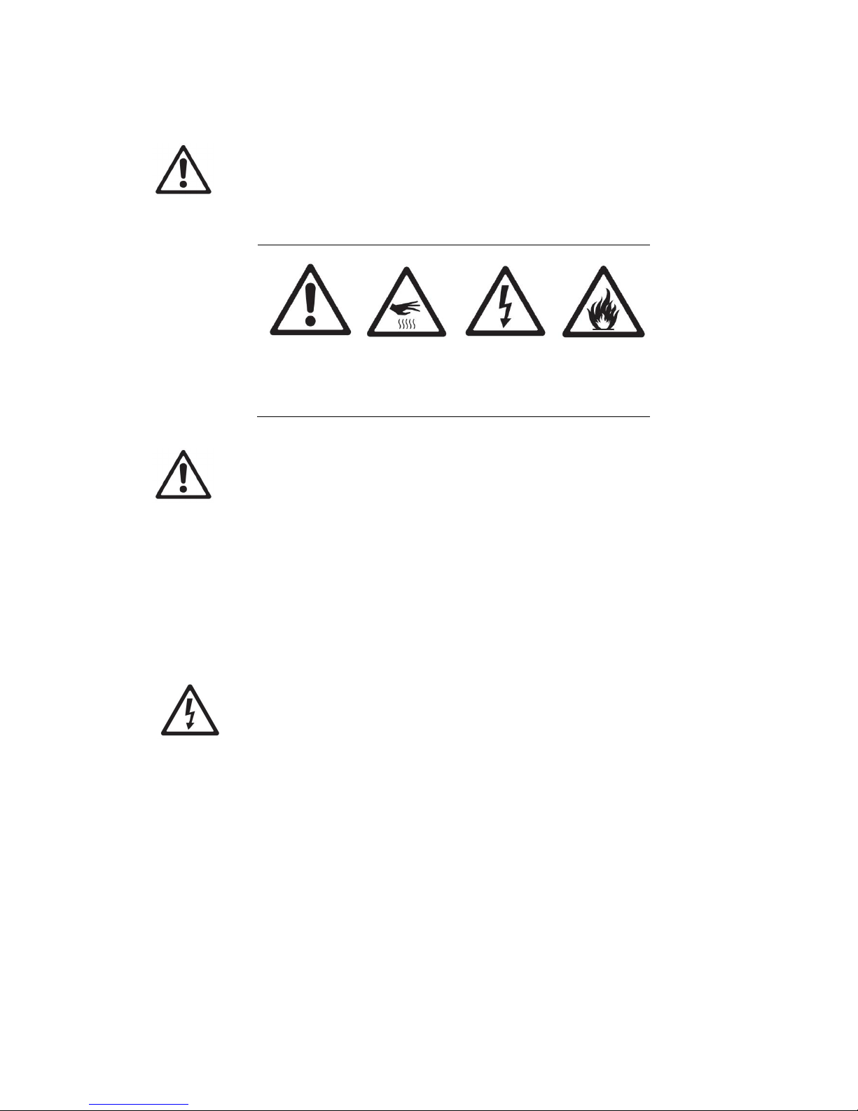
The following symbols are used to identify important safety information:
Caution! Safety
hazard. Risk of
severe injury or
death.
Caution! Burn
hazard. Hot
surface. Do not
touch.
Danger!
Hazardous
voltage. Contact
will cause electric
shock.
Caution! Fire
hazard.
Warning! This product is not for household use. It presents risks of injury due
to electric shock, burns, falls and respiratory problems!
Read this manual before operating the machine, follow the safety precautions
listed below, and observe all warnings in this manual and printed on the
machine. Use the machine only as described in this manual and in accordance
with local laws and regulations.
If you have questions about how to operate the machine safely, or if you have
followed the instructions in this manual and the machine is malfunctioning,
please contact Martin™ Service.
Pr e ve nt i ng el e ctr ic sh o ck s
Always ground (earth) the machine electrically.
Use only a source of AC power that complies with local building and
electrical codes, and that has both overload and ground-fault protection.
Before connecting the machine to power, check that the voltage
indicated on the machine’s serial label matches your local AC power
voltage. If your AC power voltage does not match, do not use the
machine. Contact Martin™ Service for assistance.
Before using the machine, check that all power distribution equipment
and cables are in perfect condition and rated for the current
requirements of all connected devices.
If the machine or any cables connected to it are in any way damaged,
defective, wet, or show signs of overheating, stop using the machine
and contact Martin™ Service for assistance. If the supply cord is
damaged, it must be replaced by a special cord or assembly available
from the manufacturer or its service agent.
Disconnect the machine from AC power before servicing and when not
in use.
Page 6
6
Safety information
This machine is not waterproof and should not be exposed to wet
outdoor conditions. Do not immerse in water or any other liquid. Do not
expose to high-pressure water jets.
Do not spill fluid over or inside the machine. If fluid is spilled, disconnect
AC power and clean with a damp cloth. If fluid is spilled onto electronic
parts, take the machine out of service and contact Martin™ for advice.
Do not remove the covers or attempt to repair a faulty machine. Refer
any service not described in this manual to Martin™.
Do not operate the machine if any parts are damaged, defective or
missing.
Moisture and electricity do not mix. Do not aim fog output at electrical
connections or devices.
Pr e ve nt i ng bur ns an d f i re
The fog produced by the machine is hot enough to cause burns when it
leaves the nozzle, and very hot droplets of fluid escape occasionally.
Keep people and objects at least 600 mm (24 in.) away from the fog
output nozzle.
Do not touch the fog output nozzle during or after use – it becomes
extremely hot and remains hot for several hours after the machine has
been shut down.
Fog output contains glycol, a flammable alcohol that burns with an
almost invisible blue flame. Do not point fog output at sources of ignition
such as open flames or pyrotechnic effects.
Do not attempt to bypass thermostatic switches, fluid sensors or fuses.
Replace fuses only with ones of the type and rating specified in this
manual for the machine.
Provide a minimum free space of 100 mm (4 in.) around the machine.
Provide a minimum free space of 500 mm (20 in.) around fans and air
vents and ensure free and unobstructed air flow to and around the
machine.
Keep the machine at least 600 mm (24 in.) away from combustible and
heat-sensitive materials.
Do not operate the machine if the ambient temperature (Ta) is below 5°
C (41° F) or above 40° C (104° F).
Do not operate the machine if the relative air humidity exceeds 80%.
Pr e ve nt i ng in j ur i es
Fasten the machine securely to a fixed surface or structure when in use.
The machine is not portable when installed.
Ensure that any supporting structure and/or hardware used can hold at
least 10 times the weight of all the devices they support.
If suspending from a rigging structure, fasten the machine to a rigging
clamp. Do not use safety cables as the primary means of support.
If the machine is installed in a location where it may cause injury or
damage if it falls, install as directed in this manual a secondary
attachment such as a safety cable that will hold the machine if a primary
attachment fails. The secondary attachment must be approved by an
official body such as TÜV as a safety attachment for the weight that it
secures, must comply with EN 60598-2-17 Section 17.6.6 and must be
Page 7

7
capable of bearing a static suspended load that is ten times the weight
of the machine and all installed accessories.
Check that all external covers and rigging hardware are securely
fastened.
Block access below the work area and work from a stable platform
whenever installing, servicing or moving the machine.
Do not operate the machine with missing or damaged covers or shields.
In the event of an operating problem, stop using the machine
immediately and disconnect it from power. Do not attempt to use a
machine that is obviously damaged.
Do not modify the machine in any way not described in this manual or
install other than genuine Martin™ parts.
Refer any service operation not described in this manual to a qualified
technician.
Fog output can cause condensation. Do not point the output at smooth
floors. Floors and surfaces may become slippery. Check these
frequently and wipe dry as necessary to avoid any danger of slipping.
Ensure at least 2 m (6.6 ft.) visibility in areas where fog is being
produced.
Fog fluid contains food-grade glycols in solution but may present health
risks if swallowed. Do not drink it. Store it securely. If eye contact
occurs, rinse with water. If fluid is swallowed, give water and obtain
medical advice.
This appliance is not intended for use by persons (including children)
with reduced physical sensory or mental capabilities, or lack of
experience and knowledge, unless they have been given supervision or
instruction concerning use of the appliance by a person responsible for
their safety. Children should be supervised to ensure that they do not
play with the appliance.
Pr e ve nt i ng br e at h ing p r ob l em s
A machine can operate safely only with the fog fluid it is designed for.
Use the machine only with fluids specified under “Approved fluid types”
on page 21 or you may cause the release of toxic gases, presenting a
severe health hazard. You will also probably damage the machine.
Do not create dense fog in confined or poorly ventilated areas.
Do not expose people with health problems (including allergic and/or
respiratory conditions such as asthma) to fog output.
Do not point fog output directly at a person’s face or at face height.
For the latest user documentation and other information for this and all Martin™
products, please visit the Martin™ website at http://www.martin.com
If you have any questions about how to install, operate or service the fixture
safely, please contact your Martin™ distributor (see www.martin.com/distributors
for details) or call the Martin™ 24-hour service hotline on +45 8740 0000, or in
the USA on 1-888-tech-180.
Page 8
8
Product overview
Product overview
P r o du ct d es c ri pt io n
The JEM ZR25™, ZR35™ and ZR45™ provide a uniquely flexible and convenient
solution to a wide range of fog requirements whether permanently installed or
taken on the road. Featuring a high efficiency heating block and accepting
multiple weights of fluid, the JEM ZR series™ products can create anything from
an ephemeral steam chase to a dense, long-lasting “whiteout”.
An advanced control panel with LCD screen can be operated on the machine or
removed and used as a remote controller, or the machines may be operated by
DMX with full RDM capability for remote setup and status monitoring.
This manual contains instructions for all machines in the range, but
some features are different. These symbols show information
which is specific to a particular machine.
Congratulations on your purchase of a JEM ZR series™ product from Martin™.
Details of the full range of Martin™ products are available on our website at
www.martin.com.
Fe a t u re s a t a gl an c e
Robust roadworthy design
Integrated digital remote control
DMX with RDM
Hanging bracket included
Continuous micro-processor controlled effect output
Diverse fluid options for different applications
Soft start technology
Fluid sensing system
Easy external fluid hook-up
Optional PLC Interface and ducting kits
Use only an approved Martin™ fog fluids as shown on page 21. Use
of other fluid will void warranty.
Page 9
9
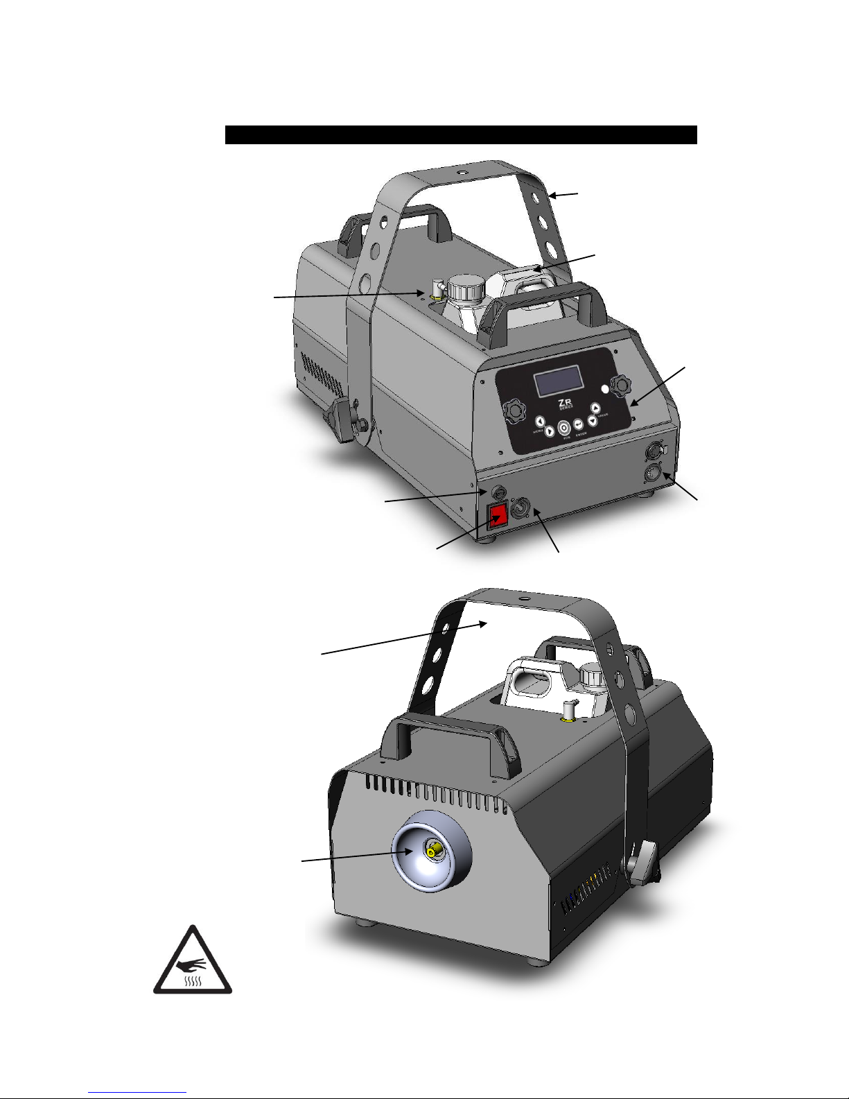
DMX input
and output
Integral hanging
bracket
Mains power
switch
Mains power
connector
Fluid pipe
connection
Fluid container
Integrated digital
remote control
Mains fuse
P r o du ct d et a il s
ZR25™
Fog output
nozzle
WARNING!
High temperature
vapor and surfaces
If suspending overhead:
Loop safety cable under
hanging bracket and
secure
Page 10
10
Product overview
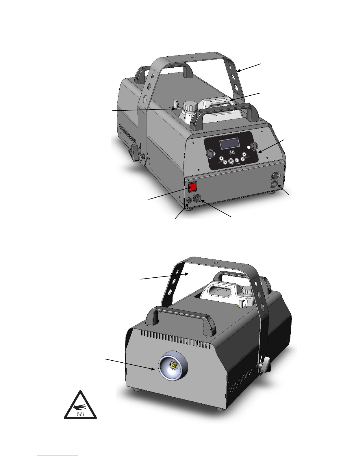
DMX input
and output
Integral hanging
bracket
Mains power
switch
Mains power
connector
Fluid pipe
connection
Fluid container
Integrated
digital remote
control
Mains fuse
ZR35™
Fog output
nozzle
WARNING!
High temperature
vapor and surfaces
If suspending overhead:
Loop safety cable under
hanging bracket and
secure
Page 11

11
DMX input
and output
Integral hanging
bracket
Mains power
switch
Mains power
connector
Fluid pipe
connection
Fluid container
Integrated digital
remote control
Mains fuse
ZR45™
Fog output
nozzle
WARNING!
High temperature
vapor and surfaces
If suspending overhead:
Loop safety cable under
hanging bracket and
secure
Page 12

12
Quick Start
Quick Start
You are no doubt eager to switch on the machine and try it out by making a lot
of fog. This section tells you how to do that. However, please also make the time
to read the safety and servicing instructions in the remainder of this manual.
Se t t i ng u p
Locate the machine in a suitably large area with nothing in front of the fog
output.
Fill the fluid tank with an approved Martin™ fog fluid as shown on page 21.
Connect the machine to a suitably rated power source. The power requirements
are:
1200W 220-240V EU / 1050W 100-130V US
1550W 220-240V EU / 1450W 100-130V US
2100W 220-240V EU / 1800W 100-130V US
Now set the mains switch on the rear of the unit, to the ‘ON’ (I) position. The
display will show HEAT. If the display shows OFF, press the FOG button on the
control panel or set the RUN MODE to CONTINUOUS. After about 6-8 minutes
the display should show FOG LEVEL (along with the set output level) and the
machine will begin producing fog. If the display shows READY press the FOG
button on the control panel.
M a k in g f o g
If you want to adjust the fog density manually, press the Menu < > buttons until
the display shows FOG LEVEL and use the Value up/down buttons to select a
value above 0% then press the Enter button to store this value.
If no fog is produced it may be necessary to prime the machine.
Press the Menu <> buttons until the display shows PRIME (located
in the SETTINGS submenu), then press the Value Up button so the
display shows YES, then press the Enter button.
Page 13

13
Installation and Setting Up
DANGER! DO NOT operate the machine until you have read and observed all
the precautions listed under “Safety information” on page 5.
Lo c at io n
The JEM ZR series™ machines are designed to be located on the floor or may
be suspended using the fitted hanging bracket. The machine can operate in any
orientation from 45 degrees upwards to 45 degrees downwards. Steeper tilting
may cause fluid leakage.
If the machine is to be suspended, ensure the mounting surface can support the
weight of the machine. Do not suspend the machine over areas where people
will be underneath. Use only the fitted hanging bracket to suspend the machine.
Ensure that there is at least 100mm (4 in.) clearance all-round the machine and
at least 600mm (24 in.) in front of the fog output.
The machine is delivered with white nylon shipping bolts fitted to
the hanging bracket in place of the normal hand-wheel bolts.
Before first use, remove the shipping bolts and replace them with
the hand-wheel bolts (outside of bracket) and spacers (inside of
bracket) which are supplied separately in the packaging.
A C po we r
Before using the machine, ensure that a grounding-type (earthed) power plug
that fits the local power outlets is installed on the power cable provided.
DANGER! Make sure the power plug is correctly rated:
For EU ZR25, ZR35, ZR45 models use a plug rated at 10 A minimum.
For US ZR25 use a plug rated at 10 A minimum.
For US ZR35 use a plug rated at 15 A minimum.
For US ZR45 use a plug rated at 20 A minimum.
When installing the plug, follow the plug manufacturer’s instructions and
connect pins as follows:
Yellow and green wire to ground (earth), blue wire to neutral and brown wire to
live.
The table below shows some common pin identification schemes.
wire
function
marking
screw colour
brown
live
“L”
yellow or brass
blue
neutral
“N”
silver
green/yellow
earth
green
Page 14

14
Installation and Setting Up
Before connecting the machine to power, verify that the AC supply is adequately
dimensioned for the current draw of the machine.
1200W 220-240V EU / 1050W 100-130V US
1550W 220-240V EU / 1450W 100-130V US
2100W 220-240V EU / 1800W 100-130V US
Check that the local AC voltage is appropriate, as indicated on the machine’s
serial number label. If your AC voltage is outside the appropriate range, do not
use the machine. Contact Martin™ Service for assistance.
Se t t i ng u p
Fill the fluid tank with an approved Martin™ fog fluid as shown on page 21. If
DMX control is being used, connect the machine to the DMX line (see page 19).
If you are using several machines from one control panel in master-slave link
mode, link the machines in a daisy-chain using the DMX input and output
sockets. It does not matter which socket is used as input or output.
Fi n a l c he c k s
Before applying power to the machine, verify the following:
the machine is safely located or installed and meets the location
requirements stated on page 13
the operator is familiar with, and able to comply with, the requirements
for safe operation listed on page 5.
the fluid is one of the Approved Martin™ fluids listed under “Approved
fluid types” on page 21.
the machine is electrically grounded (earthed)
the AC power distribution circuits and lines are adequately rated for the
current load
Tu r n i ng o n t he p ow e r
Set the mains switch on the rear of the unit, to the ‘ON’ (I) position. The display
will show HEAT. If the display shows OFF, press the FOG button on the control
panel or set the RUN MODE to CONTINUOUS. After about 6-8 minutes if no
DMX is connected the display should show FOG LEVEL (along with the set
output level) and the machine will begin producing fog. If DMX is connected the
display will show DMX when the machine is ready.
The machine will remember its state from when it was turned off last time, so it
will only power up in OFF mode if you have previously disabled the heaters.
To obtain maximum output, wait another few minutes after the READY
indication is shown, as the machine continues to heat to full operating
temperature and fog output is reduced while the unit is heating up.
Page 15

15
Control Settings
Ov e rv ie w
The integrated digital remote control on the rear of the machine allows you to
configure it using option menus.
The integrated digital remote control may be removed from the unit
and used as a handheld remote control by removing the two hand
wheel bolts either side of the display. The display cable may be
extended up to 25 m (82 ft.) using standard 3-pin XLR cable.
Se t t i ng R u n m o de s
The RUN MODE menu sets the operational mode of the machine, and can also
be used to shut down the heater. Settings are Off (shutdown, heaters off),
Standby (heaters remain on), Timer mode or Continuous mode.
Use the Menu Previous / Next buttons to select the RUN MODE option.
Use the Up/Down buttons to select OFF, STANDBY, TIMER, CONTINUOUS.
Press the Enter button to store the setting. The display shows SET.
Selecting OFF will disable the heaters on the unit.
Se t t i ng F o g ou tp u t de ns i t y
Use the Menu Previous / Next buttons to select the FOG LEVEL option.
Use the Up/Down buttons to select the density from 0% - 100%
Press the Enter button to store the fog setting. The display shows SET.
Menu previous/next
buttons
Value down/up
buttons
Digital display
Enter/store button
READY 100%
Page 16

16
Control Settings
If you want to temporarily change the fog density, do not press
Enter. The fog setting will go back to its stored value next time the
machine is powered up. This applies to all options.
Se t t i ng t he T i me r
Set the RUN TIME and OFF TIME values from the menu.
Then select the TIMER option from the RUN MODE menu.
The timer values are set in seconds and are in the range 0-99. The Fog value is
taken from the FOG LEVEL menu. The timer will cycle continuously until the run
menu is changed.
Use this mode for maintaining a low level of fog in smaller venues.
Us i n g t he S e tt in gs m e nu
Options such as the DMX base address, display brightness, DMX stand-alone
linking, priming, factory reset and temperature control (ZR45 only) are found in
the SETTINGS menu.
Use the Previous / Next buttons to select the SETTINGS option.
Press the Enter button to go to the SETTINGS menu.
To return to the main menu, use the Previous / Next buttons to select EXIT and
press Enter.
Se t t i ng t he D M X ba se ad dr es s
Use the Previous / Next buttons to select the DMX option from the SETTINGS
menu.
Use the Up/Down buttons to set the DMX base address from 001 to 511. If you
hold down the button the address will count up or down more quickly.
Press the Enter button to store the address setting.
The machine will automatically respond to a DMX controller whenever it is
connected.
When using in a DMX system ensure the LINK MODE menu is set to RECEIVE
(the default setting) to avoid causing DMX errors to other devices on the system.
Alternatively, the DMX base address can be set via RDM.
D i s pl ay b a c k l i g h t se tt i n g
You can set the brightness of the display backlight using the BACK LIGHT
option.
Use the Previous / Next buttons to select the BACK LIGHT option from the
SETTINGS menu.
Use the Up/Down buttons to change the option to LOW, NORM or HIGH.
Press the Enter button to store the setting.
Se t t i ng t he m a st er - sl a v e l in k mo d e
It is possible to control several machines from one digital remote. The machine
with the remote plugged into it is set as the Master. The other machines are set
as Slaves. The machines are interconnected with DMX cabling.
Use the Previous / Next buttons to select the LINK MODE option from the
SETTINGS menu.
Page 17

17
Use the Up/Down buttons to select RECEIVE (slave unit) or SEND (master unit).
Press the Enter button to store the link setting.
The machine should be set to SEND only if it is running as a master. If running
as a slave, stand-alone or DMX controlled it should be set to RECEIVE. If a
machine set to SEND is connected to an active DMX system, the DMX will be
corrupted causing flickering of lights and other strange symptoms.
P r i m i ng t h e ma c h i n e a ft e r fl ui d o ut
If the machine runs out of fluid, it will automatically shut down and show FLUID
OUT on the display to prevent damage to the pump(s). To suck the new fluid
back into the machine and reset the FLUID OUT error, replace/refill the fluid tank
and use the prime function.
Use the Previous / Next buttons to select the PRIME option from the SETTINGS
menu.
Use the Up/Down buttons to change the option to YES.
Press the Enter button to start the priming function.
The pump(s) will operate at full power for a short time to purge air from the
pipes inside the unit.
To exit this menu if you decide not to activate the Prime function, select NO and
press Enter.
R e s e t ti ng o p ti on s t o fa ct or y s e t t in gs
The factory settings configure a standard mode of operation for the machine.
Use the Previous / Next buttons to select the RESET option from the SETTINGS
menu.
Use the Up/Down buttons to change the option to YES.
Press the Enter button to reset all options.
To exit this menu if you decide not to reset the options, select NO and press
Enter.
Page 18

18
Control Settings
The factory settings are:
option
setting
FOG LEVEL
50%
TIMER ON
10 seconds
TIMER OFF
20 seconds
RUN MODE
STANDBY
DMX
001
BACK LIGHT
NORM
LINK MODE
RECEIVE
PRIME
NO
TEMPERATURE*
NORM
*ZR45 Only
Page 19

19
DMX Control
Ov e rv ie w
DMX is a digital control system widely used in entertainment and architectural
lighting. Any controller meeting the DMX-512 standard may be used to control
and program the fog output of the JEM ZR series™ machines.
When a DMX signal is present, the JEM ZR series™ machine’s
stand-alone functions do not work. To fire the unit from the control
panel or remote control, the DMX controller must be powered off or
disconnected.
If the DMX signal is removed (controller turned off or unplugged),
the machine will revert to its previously stored RUN MODE settings.
If the machine was set to OFF, it will revert to this state.
If the machine was set to STANDBY, it will revert to this state.
If the machine was set to TIMER, it will revert to this state.
If the machine was set to CONTINUOUS, it will revert to this state.
C o n ne ct io n
The JEM ZR series™ machine provides 5-pin XLR connectors on the rear of the
machine for DMX connection.
For best results, use cable designed for high speed digital data transmission.
D M X f un ct i o n s
The JEM ZR series™ address setting must match the DMX address allocated to
it on your controller. To set the address, see “Setting the DMX base address” on
page 16. The JEM ZR series™ machine requires one DMX channel.
When the machine is at running temperature and is under DMX control it
displays DMX (+ the current DMX base address).
The DMX control values are shown in the table below.
Channel 1
DMX value
range
Function
Macro description
Default
value
Fog output
level
0-12
Idle range
None
0
13- 240
Output 0100%
241 -255
Output 100%
Page 20

20
Optional PLC Interface Control
Optional PLC Interface Control
Ov e rv ie w
An Optional PLC interface is available that will replace the DMX functionality of
the machine and provide analog control of fog output (on and off) and fog flow
rate (0-100%) or can trigger a preset flow rate. This interface uses closedcontact signaling or can respond with 0-10V reference. Up to 5 machines can be
daisy chained and controlled in this manner (subject to the drive capability of
the controlling system). Physical connection is via 3-pin and 4-pin male locking
XLR. Please contact your Martin dealer for more detailed information on
application and ordering.
Page 21

21
Approved Fog Fluid Types
The JEM ZR series™ machines must only be used with the Martin™ fluids listed
below. Martin™ supplies high quality fog fluids that are based on ultra-pure
deionized water. No other fluid is suitable for use.
Pr o S mok e S tu d io Fl u id (D X m i x)
In a studio or theatre environment, a lighter, faster dispersing fog is often
preferred. Pro-Smoke Studio offers a less dense environment to Pro-Smoke
Super and is therefore less likely to interfere with TV camera focusing.
Pr o S mok e S up e r ( ZR mi x )
Pro Smoke Super fluid is a high-quality, general purpose fluid that produces a
dense white airborne fog with medium dispersal time. Its medium to high index
of refraction permits both good atmospheric effects and denser “white-outs”.
Pr o S mo k e H ig h D e ns i ty (S P m i x)
Pro Smoke High Density fluid generates a high density, white, airborne fog with
a very high index of refraction and slow evaporation rate. It is well suited for
scenic obscuring, dramatic strobe effects, and “white-outs”.
i- f o g F l ui d
i-fog is not only kind to your lights, but is also more economical to use thanks to
its incredible long “hang time” characteristics.
It is well suited for scenic obscuring, dramatic strobe effects, and “white-outs”.
RU S H Fog F l ui d ™
RUSH Fog Fluid™ is a specially formulated water-based fog formula and is
recommended for use with applicable Martin fog effect generators. While
economical it is perfect for medium-density airborne fog effects with medium
hang time and leaves no residue; RUSH Fog Fluid™ is designed as an economy
fluid that is suitable for use in nightclubs, bars, stage and outdoor events.
*Please note that use of RUSH Fog Fluid™ in a JEM™ series fog machine will produce a
less than expected professional quality effect due to the nature of using an entry level fog
effect fluid.
Pr o S tea m S imu la t io n
For ZR45 only - Pro Steam Simulation fluid is a light fluid that
produces well-defined cones of vapour that disperse quickly. It is
ideal for chase effects and theatrical use.
Not suitable for use with the ZR25 and ZR35.
DANGER! The JEM ZR series™ machines can run safely only on the specific
fog fluids they are designed for. Use ONLY the Martin™ fog fluids designated
in this manual. NEVER use any other type of fluid, or toxic gas may be
produced. You will probably also cause damage to the machine that will
invalidate the product warranty. Do not dilute fog fluid with water or any other
liquid. Discard fog fluid if it becomes contaminated.
To find your local dealer visit www.martin.com
Page 22

22
Approved Fog Fluid Types
T e m p er at u r e M en u
The different fluid types listed require correct selection of the relevant
temperature setting in the TEMPERATURE sub-menu of the SETTINGS menu.
Select the required temperature and press Enter to store.
The selected temperature setting will remain after power off and is indicated on
the display whilst in standby (TEMP=NORM) and also shows during manual
operation/DMX control (T=N).
TEMPERATURE Setting
Fluid Type
HIGH
Pro Smoke High Density (SP mix)
i-fog
NORM
Pro Smoke Super (ZR mix)
RUSH Fog Fluid
Pro Smoke Studio (DX mix)
LOW
Pro Steam Simulation
Page 23

23
P r o C le an S u pr em e Fl u id
Specially designed for optimum performance while providing longevity of the
heat exchanger, Pro Clean Supreme is the ultimate cleaning solution for Martin
fog and haze effect machines. Applying Pro Clean Supreme fluid on a regular
basis reduces clogging and further extends the life of Martin fog and haze
machines.
Using Pro Clean Supreme every 200 hours, or once a month (depending on
usage), will prolong the life of the heat exchanger in Martin fog and haze
machines. Connect Pro Clean Supreme fluid to the fogger or hazer, then allow
the unit to heat. When fully ready, activate the machine or remote for
approximately 30-45 minutes (use the timer function if available). When
completed, replace cleaning fluid with appropriate fluid.
Note: Cleaning procedure should be used if the unit is to be stored for 30 days
or more. Ensure there is no fluid in the fluid tube when placing in storage.
Page 24

24
Basic Service
Basic Service
Before servicing the JEM ZR series™ machines, read and observe all the
precautions listed in “Safety information” on page 5. Any service not
described in this section must be carried out by a Martin™ service technician.
To find your local Martin™ service centre visit www.martin.com/Where-to-buy
C l e an in g
Excessive dust, fog fluid, and dirt build-up will degrade performance and cause
overheating and damage to the machine that is not covered by the product
warranty. To maintain adequate cooling, dust must be cleaned from the outer
casing and air vents of the machine periodically.
Isolate the machine from power and allow to cool completely before cleaning.
The fog output nozzles remain hot for a period after use.
Remove dust from the air vents with a soft brush, cotton swab, vacuum,
or compressed air.
Clean fog fluid residues from the fog output of the machine using a
damp cloth.
Clean the outer casing with a damp cloth only.
Fu s e re pl a c e m e nt
The main fuse for the machine is located adjacent to the power inlet on the rear
panel. There is also a T3.15 A fuse located on the electronics board inside the
unit which protects the supply to the pump.
DANGER! Disconnect the power supply before removing any covers or
changing fuses. Live parts inside!
Rear panel fuse:
ZR25
EU model = 6.3 AT (slow-blow), 250V
US model = 10 AT (slow-blow), 125V
ZR35
EU model = 10 AT (slow-blow), 250V
US model = 15 AT (slow-blow), 125V
ZR45
EU model = 12.5 AT (slow-blow), 250V
US model = 20 AT (slow-blow), 125V
Replace fuse only with one of exactly the same size and rating. Contact Martin™
Service if the fuse blows repeatedly.
To replace the internal fuse, disconnect the power cord from the supply,
unscrew the screws holding the top cover of the unit and remove the cover. The
electronics board is located in the side compartment.
Page 25

25
Troubleshooting
Problem
Probable cause(s)
Suggested remedy
Machine will not produce fog
when control panel set to
CONTINUOUS or fog button
pressed
Machine not at operating
temperature
Wait until HEAT message no
longer shown
FOG option set to 0
Increase setting
Machine in timer mode and
TIMER ON set to 0
Increase setting
DMX signal present
Disconnect or turn off DMX
controller
Machine can be fired from
control panel, but not by
DMX controller
DMX address setting
incorrect
Change DMX address (page
16)
Poor connection in DMX line
Check DMX cables and
connections
LINK menu is set to SEND
Set LINK menu to RECEIVE
Fog output is weak
Machine requires priming
Use PRIME option to prime
the machine (page 17)
Wet, greasy, non-uniform
fog output, fluid drips or
spits from nozzle, or very
loud noise when firing
machine
Incompatible fog fluid
Use approved fluid!
Machine appears dead
Mains fuse blown
Replace fuse (page 24)
No power at AC cable inlet
Check power cable and
circuit breaker
Machine causes DMX errors
to occur on other units when
connected to a DMX system
LINK menu is set to SEND
Set LINK menu to RECEIVE
Loss of control from remote
Communication issue
between remote and
machine
Check cable connection
between remote and
machine
Page 26

26
Status Messages
Status Messages
message
reason
OFF
The heaters are Off, the unit is shut down.
HEAT
The unit is heating up to operating temperature.
READY
The heater is at operating temperature, but Fog is not turned
on (RUN set to STANDBY).
DMX
The heater is at operating temperature and the unit is under
DMX control.
FLUID OUT
Run out of fluid. Refill the fluid tank and operate the prime
function in the SETTINGS menu
CALIBRATION
ERROR
The machine has detected an error with its calibration
settings and will not operate. Call Martin™ Service.
SYSTEM
ERROR
The machine has detected an error in the temperature sensor
and will not operate. Call Martin™ Service.
R e s e t ti ng t h e m a c hi ne a f te r fl u i d o ut
If the machine runs out of fluid, simply refill the fluid container and follow the
priming instructions on page 17.
Page 27

27
Technical Specifications
Ph y si c al
ZR25
Length ......................................................................................... 485 mm (19.1 in.)
Width ........................................................................................... 335 mm (13.2 in.)
Height ............................................................................................ 242 mm (9.6 in.)
Height with hanging bracket ....................................................... 333mm (13.2 in.)
Weight, dry ................................................................................... 11.2 kg (24.7 lb.)
Weight, filled ................................................................................. 13.7 kg (30.2 lb.)
ZR35
Length ......................................................................................... 590 mm (23.3 in.)
Width ........................................................................................... 395 mm (15.6 in.)
Height ........................................................................................... 264mm (10.4 in.)
Height with hanging bracket ....................................................... 351 mm (13.9 in.)
Weight, dry ................................................................................... 15.1 kg (33.3 lb.)
Weight, filled ................................................................................. 19.1 kg (42.1 lb.)
ZR45
Length ......................................................................................... 602 mm (23.1 in.)
Width ........................................................................................... 395 mm (15.6 in.)
Height .......................................................................................... 306 mm (12.1 in.)
Height with hanging bracket ....................................................... 393 mm (15.5 in.)
Weight, dry ................................................................................... 17.7 kg (39.1 lb.)
Weight, filled ................................................................................. 22.7 kg (50.0 lb.)
Pe r fo rma nce
ZR25
Coverage volume .................................................... 600 m³ (21,189 ft³) per minute
Fluid consumption (max.) ................................................... 40 ml per 30 seconds
Continuous effect output.
Ready time .............................................................................................. 7 minutes
ZR35
Coverage volume .................................................... 800 m³ (28,252 ft³) per minute
Fluid consumption (max.) ................................................... 50 ml per 30 seconds
Continuous effect output.
Ready time .............................................................................................. 9 minutes
ZR45
Coverage volume .................................................. 1300 m³ (45,909 ft³) per minute
Fluid consumption (max.) ................................................... 80 ml per 30 seconds
Continuous effect output.
Ready time ............................................................................................ 10 minutes
Co ntr ol an d p r og r am m in g
Control options .......................................... Integrated digital remote control, DMX
..................................................... optional PLC interface, master/slave link mode
Control parameters .................................... Continuous or timer-controlled output
Fog ....................................................................... Variable output control, 0-100%
Page 28

28
Technical Specifications
DMX channels ...................................................................................................... 1
DMX compliance .................................................. ANSI E1.11 - USITT DMX512-A
RDM compliance ................................................................ANSI/ESTA E1.20 RDM
Co nst ruc tio n
Housing ...................................................................................... Steel & aluminium
Hanging bracket...............................Integrated yoke with safety attachment point
Color ............................................................................................................... Black
Heat exchanger, ZR25 ...............................................1150 W, thermally protected
Heat exchanger, ZR35 ...............................................1500 W, thermally protected
Heat exchanger, ZR45 EU .........................................2000 W, thermally protected
Heat exchanger, ZR45 US .........................................1800 W, thermally protected
Fluid pump, ZR25, ZR35 ..................................... Oscillating piston, high pressure
Fluid pump, ZR45 ....................................... Dual oscillating piston, high pressure
Fluid management ............................. Fluid out sensing, sealed for transportation
Fluid reservoir, ZR25 ................... 2.5 l drop-in reservoir with quick-connect fitting
Fluid reservoir, ZR35 ............... 4 or 5 l drop-in reservoir with quick-connect fitting
Fluid reservoir, ZR25 ...................... 5 l drop-in reservoir with quick-connect fitting
External fluid control ......................................................................... Fluid sensing
Remote control ...................... Integrated digital remote with 3 m cable, 3-pin XLR
In s ta ll a ti o n
Mounting ................................................................................ Standing or hanging
Clearance around machine.............................................................. 100 mm (4 in.)
Orientation ................................................................. Up to +/- 40° from horizontal
Co nne c ti o ns
AC Power ..................................................................... Neutrik PowerCON TRUE1
DMX, Link mode in/out................................................................ 5-pin locking XLR
Remote control ............................................................................ 3-pin locking XLR
Firmware .............................................................................................. AVR socket
Optional PLC interface .................................................... 3- and 4-pin locking XLR
El e ct ric a l
All models
AC power (EU models) .............................................220-240 V nominal, 50/60 Hz
AC power (US models) .............................................100-130 V nominal, 50/60 Hz
ZR25
Main fuse (220-240V power) .......................................... 6.3AT (slow-blow), 250 V
Main fuse (115-125V power) ........................................... 10AT (slow-blow), 125 V
ZR35
Main fuse (220-240V power) ........................................... 10AT (slow-blow), 250 V
Main fuse (115-125V power) ........................................... 15AT (slow-blow), 125 V
ZR45
Main fuse (220-240V power) ........................................ 12.5AT (slow-blow), 250 V
Main fuse (115-125V power) ........................................... 20AT (slow-blow), 125 V
Ty p ic a l Po w er an d Cu rr e nt
ZR25 (EU model) ............................................................................ 1200 W, 5.3 A*
ZR25 (US model) ............................................................................ 1050 W, 8.8 A*
ZR35 (EU model) ............................................................................ 1550 W, 6.8 A*
ZR35 (US model) .......................................................................... 1450 W, 12.1 A*
ZR45 (EU model) ............................................................................ 2100 W, 9.2 A*
ZR45 (US model) ............................................................................. 1800 W, 15 A*
*Measurements made at nominal voltage. Allow for a deviation of +/-10%
Page 29

29
Th e rm al
Maximum ambient temperature (Ta max) ............................................ 40°C (104°F)
Exterior surface temperature, steady state, at 20°C ambient ................ 30°C (86°F)
Max nozzle temperature ..................................................................... 290°C (554°F)
Minimum ambient temperature (Ta min) ................................................. 5°C (41°F)
Ap p ro va l s
EU Model
EU safety: .................................................................. EN 60 335-1+A15, EN62233
EU EMC: ..............................................................................................EN 61000-6-3
EU Immunity: .......................................................................................EN 61000-6-1
Australia/NZ (pending) ...................................................................................... RCM
US Model
US safety ....................................................................................................... UL 998
Canada safety ....................................................................... CSA C22.2 No.104.01
In c lu ded i t em s :
User manual ...................................................................................... P/N 35010042
Fluid reservoir ZR25, 2.5 l ................................................................. P/N 34300521
Fluid reservoir ZR35, 4 l .................................................................... P/N 34300523
Fluid reservoir ZR45, 5 l .................................................................... P/N 34300506
JEM ZR series™ Digital Remote Control ........................................... P/N 55765048
ZR25/35/45 EU, power input cable, PowerCON TRUE1, stripped ends, 3 m (9.8
ft.) ...................................................................................................... P/N 11501043
ZR25 US, power input cable, 10A, PowerCON TRUE1, molded NEMA 5-15P,
3 m (9.8 ft.) ........................................................................................ P/N 11501044
ZR35 US, power input cable, 15A, PowerCON TRUE1, molded NEMA 5-15P,
3 m (9.8 ft.) ........................................................................................ P/N 11501045
ZR45 US, power input cable, 20A, PowerCON TRUE1, molded NEMA 5-20P,
2 m (6.6 ft.) ........................................................................................ P/N 11501046
Ac c es s or ies
JEM ZR series™ PLC Interface .......................................................... P/N 92765049
JEM ZR25™Ducting System, with 5 m (16.4 ft.) ducting ................... P/N 92625012
JEM ZR35™Ducting System, with 5 m (16.4 ft.) ducting ................... P/N 92625013
JEM ZR45™Ducting System, with 5 m (16.4 ft.) ducting ................... P/N 92625014
Approved Fluids
JEM™ Pro Smoke Studio
JEM™ Pro Smoke Super
JEM™ Pro Smoke High Density
JEM™ i-Fog Fluid
JEM™ Pro Steam Simulation (ZR45 only)
JEM™ Pro Clean Supreme
*Various sizes available – contact your dealer or see martin.com for details.
Installation Hardware
Half-coupler clamp ............................................................................. P/N 91602005
G-clamp (vertical hanging suspension only) ..................................... P/N 91602003
Quick trigger clamp (vertical hanging suspension only) ................... P/N 91602007
Service Tools
Epsilon 5 AVR Programmer ............................................................... P/N 50502004
Temperature Calibration Box ............................................................. P/N 92620005
Page 30

30
Technical Specifications
Or der ing i n fo r ma t io n
JEM ZR25™, US ................................................................................. P/N 92215330
JEM ZR25™, EU ................................................................................. P/N 92215320
JEM ZR35™, US ................................................................................. P/N 92215350
JEM ZR35™, EU ................................................................................. P/N 92215340
JEM ZR45™, US ................................................................................. P/N 92215370
JEM ZR45™, EU ................................................................................. P/N 92215360
Specifications subject to change without notice. For the latest technical specifications, see
www.martin.com
Page 31

31
Disposing of this product
Martin™ products are supplied in compliance with Dire ctive 2002/9 6/EC of the European
Parliament and of the Council of the European Union on WEEE (Waste Electrical and
Electron ic Equipment), as amended by Dire ctive 2003/1 08/EC, where applicable.
Help preserve the environment! Ensure tha t this product is recycled at the end of its life.
Your supplier can give de tails of local arrange ments for the disposal of Martin products.
Page 32

www.martin.com • Olof Palmes Allé 18 • 8200 Aarhus N • Denmark
Tel: +45 8740 0000 • Fax: +45 8740 0010
 Loading...