

Page 1
JEM Glaciator X-Stream
SERVICE MANUAL
Revision A, 06-19-2017, Level 1
Page 2

Service manual
2 of 24JEM Glaciator X-Stream - Revision A, 06-19-2017, Level 1
Table of contents
General information .................................................................................................................3
Safety instructions .......................................................................................................................................3
Preventing electric shocks ...............................................................................................................4
Preventingburnsandre .................................................................................................................5
Preventing injuries .............................................................................................................................5
Preventing breathing problems ........................................................................................................ 6
Tools .............................................................................................................................................................. 6
Spare parts....................................................................................................................................................7
Product information .....................................................................................................................................7
Repair and maintenance ....................................................................................................... ...8
Heat exchanger calibration .........................................................................................................................8
Heat exchanger calibration - analog PCB ........................................................................................ 8
Heat exchanger calibration - digital PCB ....................................................................................... 11
Fluid pump speed calibration ..................................................................................................................14
Fluid sensor calibration ..................................................................................................................15
Refrigeration system..................................................................................................................................17
Refrigeration system check ............................................................................................................ 17
Temperature values .........................................................................................................................18
Rear fan diagnostics ..................................................................................................................................19
Sight glass level check ..............................................................................................................................19
Condensate drain .......................................................................................................................................20
Firmware updates.......................................................................................................................................20
Maintenance ............................................................................................................................21
Cleaning the product .................................................................................................................................21
Casework, fan, drip tray cleaning ................................................................................................... 21
Airltermaintenance ......................................................................................................................22
Heat exchanger cleaning .................................................................................................................22
Maintenance schedule ...............................................................................................................................23
Page 3
Service manual
3 of 24JEM Glaciator X-Stream - Revision A, 06-19-2017, Level 1
Figure 1: Safety instructions
General information
This service manual contains information about how to
service JEM Glaciator X-Stream.
Safety instructions
Read the safety precautions in this
manual before installing, operating
or servicing this product.
Warning!
This product is not for household
use. It presents risks of injury due
to electric shock, burns, falls and
respiratory problems!
The following symbols are used to identify important
safety information:
Danger!
Hazardous voltage. Contact will
cause electric shock.
Caution!
Burn hazard. Hot surface. Do not
touch.
Caution!
Safety hazard. Risk of severe injury
or death.
Caution!
Fire hazard.
Read this manual before operating the machine, follow
the safety precautions listed below, and observe all
warnings in this manual and printed on the machine.
Use the machine only as described in this manual and
in accordance with local laws and regulations.
If you have questions about how to operate the
machine safely, or if you have followed the instructions
in this manual and the machine is malfunctioning,
please contact Martin™ Service.
Page 4
Service manual
4 of 24JEM Glaciator X-Stream - Revision A, 06-19-2017, Level 1
Figure 2: Preventing electric shocks
Preventing electric shocks
• Always ground (earth) the machine electrically.
• Use only a source of AC power that complies with
local building and electrical codes, and that has
both overload and ground-fault protection.
• Before connecting the machine to power, check
that the voltage indicated on the machine’s serial
label matches your local AC power voltage. If your
AC power voltage does not match, do not use the
machine. Contact Martin™ Service for assistance.
• Before using the machine, check that all power
distribution equipment and cables are in perfect
condition and rated for the current requirements of
all connected devices.
• If the machine or any cables connected to it are
in any way damaged, defective, wet, or show
signs of overheating, stop using the machine
and contact Martin™ Service for assistance. If
the supply cord is damaged, it must be replaced
by a special cord or assembly available from the
manufacturer or its service agent.
• Disconnect the machine from AC power before
servicing and when not in use as directed.
• This machine is not waterproof and must not
be exposed to wet outdoor conditions. Do not
immerse in water or any other liquid. Do not
expose to high-pressure water jets.
• Do not spill uid over or inside the machine. If
uid is spilled, disconnect AC power and clean
with a damp cloth. If uid is spilled onto electronic
parts, take the machine out of service and contact
Martin™ for advice.
• Do not remove the covers or attempt to repair a
faulty machine. Refer any service not described in
this manual to Martin™ Service.
• Do not operate the machine if any parts are
damaged, defective or missing.
• Moisture and electricity do not mix. Do not aim fog
output at electrical connections or devices.
Page 5
Service manual
5 of 24JEM Glaciator X-Stream - Revision A, 06-19-2017, Level 1
Figure 3: Preventingburnsandre
Figure 4: Preventing injuries
Preventingburnsandre
• Do not attempt to bypass thermostatic switches,
uid sensors or fuses.
• Replace fuses only with ones of the type and
rating specied in this manual for the machine.
• Provide a minimum free space of 500 mm (20 in.)
around the machine.
• Provide a minimum free space of 500 mm (20 in.)
around fans and air vents and ensure free and
unobstructed air ow to and around the machine.
• Do not operate the machine if the ambient
temperature (Ta) is below 5° C (41° F) or above
40° C (104° F).
Preventing injuries
• Check that all external covers are securely
fastened.
• Do not operate the machine with missing or
damaged covers or shields.
• In the event of an operating problem, stop using
the machine immediately and disconnect it from
power. Do not attempt to use a machine that is
obviously damaged.
• Do not modify the machine in any way not
described in this manual or install other than
genuine Martin™ parts.
• Refer any service operation not described in this
manual to a qualied technician.
• Fog output can cause condensation. Do not point
the output at smooth oors. Floors and surfaces
may become slippery. Check these frequently
and wipe dry as necessary to avoid any danger of
slipping.
• Ensure at least 2 m (6.6 ft.) visibility in areas
where fog is being produced.
• Fog uid contains food-grade glycols in solution
but may present health risks if swallowed. Do not
drink it. Store it securely. If eye contact occurs,
rinse with water. If uid is swallowed, give water
and obtain medical advice.
• This appliance is not intended for use by persons
(including children) with reduced physical sensory
or mental capabilities, or lack of experience
and knowledge, unless they have been given
supervision or instruction concerning use of the
appliance by a person responsible for their safety.
Children should be supervised to ensure that they
do not play with the appliance.
Page 6
Service manual
6 of 24JEM Glaciator X-Stream - Revision A, 06-19-2017, Level 1
Figure 5: Safety instructions
Figure 6: Tools
Figure 7: ESD mat and wristband
Preventing breathing problems
• A machine can operate safely only with the fog
uid it is designed for. Use the machine only with
uids specied or you may cause the release of
toxic gases, presenting a severe health hazard.
You will also probably damage the machine.
• Do not create dense fog in conned or poorly
ventilated areas.
• Do not expose people with health problems
(including allergic and/or respiratory conditions
such as asthma) to fog output.
• Do not point fog output directly at a person’s face
or at face height.
Tools
Make sure that the tools below are available before you
start working on the product.
• Pozi-driver #0, 1, 2
• Epsilon 5 Programmer (P/N: 50502004)
• Slotted screwdriver #0
• Temperature calibration box (P/N: 92620005)
• Digital multimeter with probes
• Flashlight or work light.
Take the necessary precautions
to prevent static electricity from
damaging the product during
modication or repair.
Page 7
Service manual
7 of 24JEM Glaciator X-Stream - Revision A, 06-19-2017, Level 1
Product information
Before you start servicing the product, read and do the
following:
• Observe all safety precautions.
• Disconnect all cables and the mains power cord
from the machine where required.
• Place the machine on a at solid working surface.
• Lock the braking casters.
• MachinesproducedafterApril2012aretted
with digital mains PCBs and require different
maintenance procedures. Please note the
year of manufacture on your machines serial
number label for correct procedures.
Figure 8: Partnder:Layered
Figure 9: JEM Glaciator X-Stream
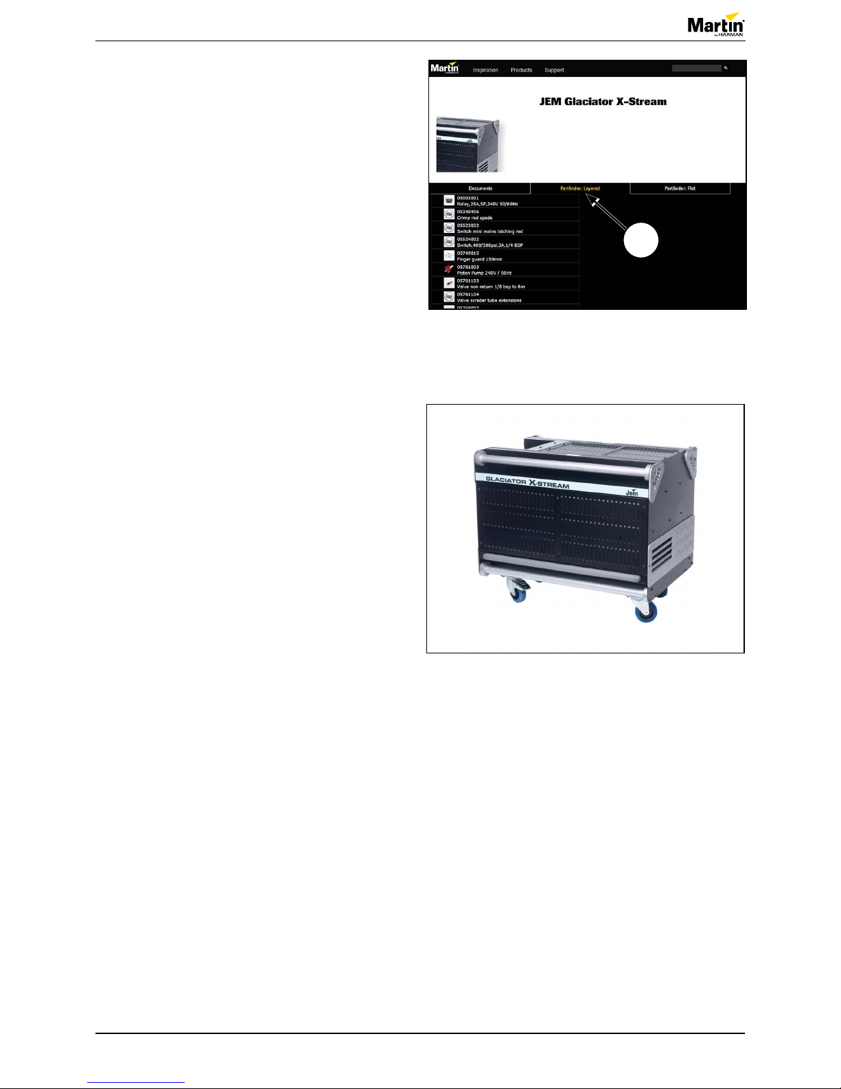
Spare parts
For an overview of the spare parts and spare part
numbers of JEM Glaciator X-Stream, refer to
martin.com.
1. Login with your user login details.
2. Search for “JEM Glaciator X-Stream”.
3. Clik “Partnder: Layered” (1).
For the latest user documentation and other
information for this and all Martin™ products, please
visit the Martin™ website at
martin.com.
If you have any questions about how to install, operate
or service the xture safely, please contact your
Martin™ distributor (see
www.martin.com/where-to for
details) or call the Martin™ 24-hour service hotline on
+45 8740 0000, or in the USA on 1-888-tech-180.
1
Page 8
Service manual
8 of 24JEM Glaciator X-Stream - Revision A, 06-19-2017, Level 1
Repair and maintenance
Heat exchanger calibration
The heat exchanger will require calibration after 1000
hours of operation or annually. This procedure will
take about 45 minutes to complete and requires the
temperature calibration box, available from Martin™.
This procedure is for qualied service personnel only
and only those competent should perform the task.
• For machines tted with analog PCBs
(manufactured before April 2012) follow the
procedure in “Heat exchanger calibration - analog
PCB” on page 8.
• For machines tted with digital mains PCBs utilize
the procedure in “Heat exchanger calibration digital PCB” on page 11.
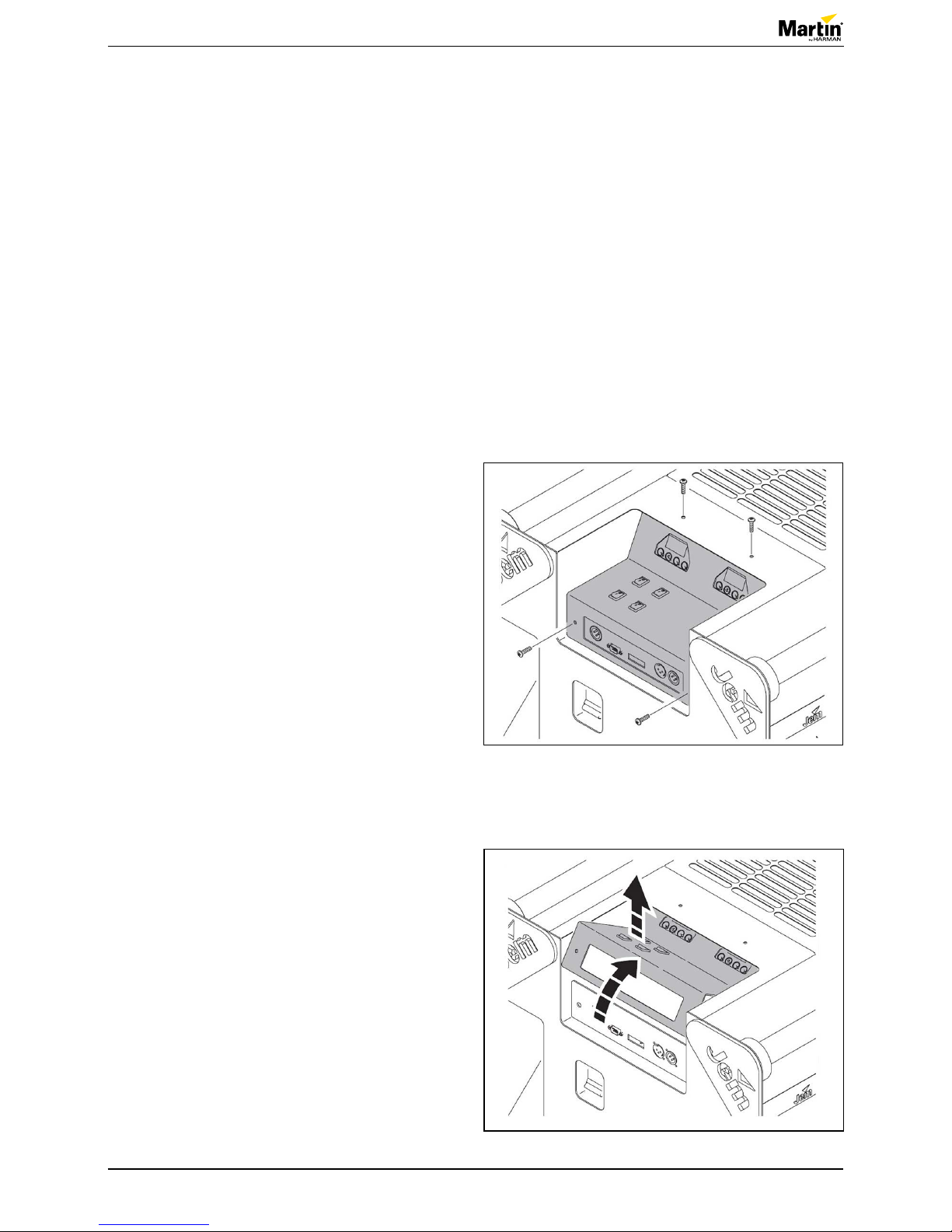
Heat exchanger calibration - analog PCB
1. Power off the machine.
2. Remove the control panel access cover (four M5
screws).
Figure 10: Removing the cover
Figure 11: Lifting the cover
3. Lift the control panel access cover up.
Page 9

Service manual
9 of 24JEM Glaciator X-Stream - Revision A, 06-19-2017, Level 1
Figure 12: Mains PCB
Figure 13: Disconnecting the thermocouple wires
4. Locate the mains PCB.
5. Disconnect the thermocouple wires from their
spade terminals, PL4 (1) and PL5 (2). See gure
12.
NOTE! If your machine was manufactured prior
to November 2006 these wires may be colored
green and yellow. Green is negative (-), and
yellow is positive (+).
6. Replace the thermocouple wires with the
calibration box leads.
NOTE! The correct orientation: Red is positive,
PL5 and black is negative, PL4.
7. Power on the calibration box.
8. Set the ramp button to off (LED ashing green)
and depress the VAR button (LED on steady red).
9. Use the variable slider to set the calibration point
to 11.5 mV.
10. Power on the machine.
Danger!
Take precaution to limit exposure to
live wires.
Figure 14: Replacing thermocouple wires
2 1
Page 10

Service manual
10 of 24JEM Glaciator X-Stream - Revision A, 06-19-2017, Level 1
11. On the mains PCB, adjust potentiometer P1 until
the red heating LED on the PCB starts to ash.
See gure 16.
12. On the calibration box, turn ramp button on (LED
on steady green). The red LED on the PCB
should go off.
13. For verication, turn the ramp button off (LED
ashing green), and the red heating LED on the
PCB should start ashing again.
14. Adjust if necessary following directions from step
11.
15. Power off and disconnect the calibration box.
16. Replace the thermocouple wires onto the correct
terminals.
NOTE! Thermocouple wires are colored black/
white and white. Black/white is positive (+), PL5
and white is negative (-), PL4. See gure 13.
NOTE! If your machine was manufactured prior
to November 2006 these wires may be colored
green and yellow. Yellow is positive (+), PL5 and
green is negative (-), PL4.
Figure 15: Adjusting potentiometer
Figure 16: RedLEDisashing
Figure 17: Connecting a digitial multimeter
17. Connect a digital multimeter to the thermocouple
connectors. Positive to PL5 and negative to PL4.
18. Power on and set DMM to read mV DC.
19. Allow the machine to heat to the ready state.
DMM values should rise as machine heats.
20. DMM should read 11.5 mV when the machine
displays “RDY” and the red LED on the PCB turns
off.
21. Re-calibrate if necessary starting from step 7.
22. If no re-calibration is required, turn off and unplug
the machine.
23. Remove the DMM probes and replace the control
panel access cover and fasten the four M5
screws.
24. If re-calibration is not possible, the PCB may need
to be replaced. Contact Martin service for detailed
instructions to proceed.
Page 11

Service manual
11 of 24JEM Glaciator X-Stream - Revision A, 06-19-2017, Level 1
Heat exchanger calibration - digital PCB
1. Power off the machine.
2. Remove the control panel access cover (four M5
screws).
Figure 18: Removing the cover
Figure 19: Lifting the cover
Figure 20: Digital mains PCB
3. Lift the control panel access cover up.
4. Locate the digital mains PCB.
Page 12

Service manual
12 of 24JEM Glaciator X-Stream - Revision A, 06-19-2017, Level 1
Figure 21: Disconnecting thermocouple wires
Figure 22: Replacing thermocouple wires
5. Disconnect thermocouple wires. See gure 20
and gure 21.
6. Replace the thermocouple wires with the
calibration box leads.
NOTE! The correct orientation: Red is positive,
PL5 and black is negative, PL4.
7. Power on the calibration box.
8. Set the ramp button to on (LED on green) and
depress the VAR button (LED on red).
9. Use the variable slider to set the calibration point
to 11.5 mV.
Figure 23: Replacing thermocouple wires
10. On the mains PCB move the temperature
calibration “TCAL” jumper to the calibration
position, by moving over one position.
11. Power on the machine.
Danger!
Take precaution to limit exposure to
live wires.
12. The machine should be in calibration mode;
indicated by a ashing red and green LEDs on the
mains PCB.
13. Count to ten and remove the TCAL jumper all
together. The LEDs should ash slowly.
14. Turn the machine off.
15. Replace the TCAL jumper back to its original pin
positions.
16. Power off and disconnect the calibration box from
the mains PCB.
Page 13

Service manual
13 of 24JEM Glaciator X-Stream - Revision A, 06-19-2017, Level 1
Figure 24: Replacing the thermocouple wires
17. Replace the thermocouple wires to the mains
PCB.
NOTE! The thermocouple wires are colored black/
white and white. Black/white is positive (+) PL5,
and white is negative (-) PL4.
18. Connect a digital multimeter to the thermocouple
connectors. Positive to PL5 and negative to PL4.
19. Power on and set DMM to read mV DC.
20. Allow the machine to heat to the ready state.
NOTE! DMM values should rise as machine
heats.
21. DMM should read 11.5 mV when the machine
displays “RDY” and the red LED on the PCB turns
off and green turns on.
22. Re-calibrate if necessary starting from step 7.
23. If no re-calibration is required, turn off and unplug
the machine.
24. Remove the DMM probes and replace the control
panel access cover and fasten the four M5
screws.
25. If re-calibration is not possible, the PCB may need
to be replaced.
Contact Martin service or replace utilizing “PCBA
power HFGX, 230V 50/60Hz, Tiny 44 – P/N:
62020130”.
Page 14

Service manual
14 of 24JEM Glaciator X-Stream - Revision A, 06-19-2017, Level 1
4. Locate the mains PCB.
5. Power on the machine and allow the machine to
heat up.
Danger!
Take precaution to limit exposure to
live wires.
6. Set the fog output level to one (1) on the left side
LCD display.
7. Turn dipswitch S2 to ON for pump ramp override.
Fluid pump speed calibration
For older machines (manufactured before April 2012)
tted with an analog mains PCB pump speed re-
calibration is necessary annually or after every 1000
service hours. The below procedure will take about 45
minutes and is intended for qualied service personnel
only. Newer machines (produced after April 2012) do
not require this procedure.
1. Power off the machine.
2. Remove the control panel access cover (four M5
screws).
Figure 25: Removing the cover
Figure 26: Lifting the cover
3. Lift the control panel access cover up.
Figure 27: Mains PCB
Page 15

Service manual
15 of 24JEM Glaciator X-Stream - Revision A, 06-19-2017, Level 1
Figure 29: Turning pot P2 on
11. Turn pot “P2” on the mains PCB until the voltage
to the pump reads 90 V DC.
12. Check the fog ow output at the front of the
machine.
NOTE! A smooth ow should be visible. If not
quite enough, adjust slightly higher.
13. The pump is now calibrated.
14. Power off and unplug the machine.
15. Remove the DMM probes and close the control
panel access cover replacing the four M5 screws.
16. Turn off dipswitch S2.
Figure 28: Placing the probes
8. Turn on DMM and set to measure volts DC.
9. Place the probes across the pump positive (PL6)
and negative (PL9) terminals.
10. Press the “Fog” on button on the control panel.
Figure 30: Fluid sensor PCB
Fluid sensor calibration
The machine utilizes an electronic uid sensor that
periodically needs calibration. We recommended that
you perform this task every 1000 hours or annually.
This procedure should take about 30 minutes and
requires a, Pozi-drive #2, slotted driver #0, and a DMM.
1. Ensure the uid reservoir is lled and place the
uid inlet tubing (with sensor) into the uid.
2. Remove the left side maintenance cover by
removing the four M5 screws.
3. Gently remove the ground wire, and set aside.
4. Locate the uid sensor PCB.
NOTE! It is on the front side of the machine just
behind the uid compartment.
Page 16

Service manual
16 of 24JEM Glaciator X-Stream - Revision A, 06-19-2017, Level 1
Figure 31: ConnectingDMMtouidsensor
Figure 32: Turning the potentiometer
Figure 33: Turning the potentiometer
5. Connect the DMM to the uid sensor PCB placing
the positive lead onto “TP1” and the negative lead
onto “ground”. See gure 31 and gure 33.
6. Power on the machine.
Danger!
Take precaution to limit exposure to
live wires.
7. Turn on and set the DMM to read mV DC, 2V
NOTE! The sensor should read 2.20 mV. If the
reading is higher or lower than 2.20 mV, the PCB
requires calibration.
8. If no calibration is necessary, proceed to step 12.
9. To re-calibrate, locate and turn the potentiometer
“P01” in the direction that will allow the uid
sensor to settle at 2.20 mV using a slotted driver
#0.
NOTE! Clockwise will increase the reading and
counter-clockwise will decrease the reading.
10. When the DMM reads 2.20 mV, remove the uid
sensor from the uid bottle.
NOTE! The reading on the DMM will climb to 2.45
- 2.51 mV and the red LED on the top of the uid
sensor PCB will illuminate; indicating “uid out”.
11. Place the uid sensor back into the uid, the DMM
should now read 2.20 mV and the red LED should
turn off. The sensor is calibrated correctly.
12. If the sensor was successfully calibrated, power
off and unplug the machine. If calibration was
unsuccessful proceed to step 15.
13. Replace the left side maintenance cover, ensuring
the grounding wire is rmly connected and tighten
the four M5 screws.
14. Secure the uid reservoir back in the uid
compartment.
15. If calibration was unsuccessful, the uid sensor
PCB is likely faulty. Replace it with “Loom uid
sensor c/w wire &h, P/N: 11862026”.
Page 17

Service manual
17 of 24JEM Glaciator X-Stream - Revision A, 06-19-2017, Level 1
Abbreviation Value
AI No function at present
TA Ambient temperature
EO Evaporator outlet
EO Evaporator inlet
CO Condenser output
CI Condenser input
Figure 34: Abbreviations
TA EO EI CO CI
Figure 35: Record your readings
Refrigeration system
The refrigeration system of the machine is a closed
loop refrigeration system and requires no preventative
or periodic maintenance for the lifetime of the product.
Should a component fail or a refrigeration leak be
suspected, immediately contact Martin Service.
Please contact Martin™ Service if you require service
or support with the refrigeration system. A system
check of the refrigeration system can be reviewed to
determine that the system is operating with optimal
performance. Please see the following section for the
details of this procedure.
Refrigeration system check
1. To check the status of the refrigeration system at
any time, use the ICE menu by putting S3 down
(dipswitch 12).
2. The left hand panel will now display the name of
the sensor on the left hand display, while the right
hand display will show the temperature value.
3. Use the scroll keys on the right hand display to
move through the available values.
NOTE! These values represent the temperatures
at specic locations within the refrigeration
system.
Follow the procedure below, notating the values of
each sensor and compare to the values on page 18.
1. Turn the machine on.
2. Ensure the ICE button is ON.
3. Ensure STANDBY is ON.
4. Turn switch S3 ON - DO NOT FIRE THE
MACHINE.
5. Leave the machine for 30 minutes to stabilize.
6. Scroll through the ICE menu and record your
readings in the table to the right.
Page 18

Service manual
18 of 24JEM Glaciator X-Stream - Revision A, 06-19-2017, Level 1
TA EO EI CO CI
15 -39 -42 57 17
16 -38 -41 57 18
18 -37 -39 60 20
20 -35 -38 62 22
22 -34 -37 63 24
24 -33 -36 66 26
26 -33 -36 66 28
28 -33 -34 58 28
30 -33 -34 58 28
Figure 36: Record your readings
TA EO EI CO CI
Figure 37: Ice no/no fog (tick over) after 40 minutes
TA EO EI CO CI
15 -14 4 71 27
16 -12 6 72 28
18 -10 8 73 30
20 -10 11 75 33
22 -10 11 77 34
24 -8 12 80 37
26 -7 12 81 38
28 -6 12 81 39
30 -6 13 81 42
Figure 38: Fog on level 20 after 5 minutes
7. Now re the machine at full output (S3 off, set to
Level 20, Fog ON) for 5 minutes.
8. After 5 minutes, keep the machine ring and
record your readings (S3 ON) in the table to the
right.
Temperature values
The temperatures specied in the tables to the right
are only a guide. These temperatures will vary from
machine to machine.
These temperatures can be used for reference and
diagnostic assistance when servicing/repairing the
machine.
If your measurements are within the range, then no
action is necessary. If your measurements are not
within range, contact Martin™ Support.
Page 19

Service manual
19 of 24JEM Glaciator X-Stream - Revision A, 06-19-2017, Level 1
Rear fan diagnostics
The rear fans should be visually and audibly checked
for operation every 250 hours for correct operation. The
rear fans are what propel the fog from the machine and
are vital to operation.
To verify fan operation simply operate the machine
manually from the control panel.
1. Turn on “ICE” and “Standby” then allow the
machine to get to its ready state.
2. Once ready, set fog output at 10 on the left hand
display and density to “Hi” on the right hand
display.
NOTE! The fan speed should be low and the fan
noise should match that speed.
3. Set density to “Nor”, the fan speed and noise
should increase.
4. Set the density to “Lo”, the fan should now be
operating at full speed.
If the fan speeds do not change or the fan is not
running at all, contact Martin™ Support for service and
support.
Sight glass level check
Inside of the uid compartment is a sight glass
for visual indication of the refrigeration’s systems
operation. Check this sight glass every 1000 hours
or annually, alongside the refrigeration system check,
“Refrigeration system check” on page 17.
1. Open the uid compartment door and locate the
sight glass.
NOTE! A ashlight or work light may be necessary
to better illuminate the space.
2. With the machine powered on and in its ready
state but not producing fog, observe the sight
glass.
There will be visible liquid level rising and falling in
the sight glass.
3. There is no dened level but the rising and falling
should time with the expansion valve opening/
closing, which can be audibly observed by the
clicking/surging noise the machine’s emits,
approximately every 10-15 seconds.
4. If no level is seen and clicking noise is more
frequent than normal, a possible refrigeration leak
is possible. Contact Martin™ Service for service
and support.
Page 20

Service manual
20 of 24JEM Glaciator X-Stream - Revision A, 06-19-2017, Level 1
Condensate drain
When operating the machine for long periods, there will
always be a buildup of condensation in the evaporator
unit. This will drain into the drip tray, which should be
emptied and cleaned regularly.
For installation purposes, a drain hose can be tted into
the condensate drain hole.
A visual inspection of the condensate drain should be
performed every 500 hours or semi-annually. When
performing an inspection, it is only necessary to verify
that waste water is properly draining from the drain
hole or drain hose.
Caution!
Isolate the machine from power and
allow it to cool completely before
performing the following procedure.
1. If the drain hose or drain hose appears to be
clogged, clear the obstruction.
2. Use a small slotted screwdriver or an awl and
simply dislodge any debris out of the way of the
hole or clear the hose.
3. If an obstruction cannot be cleared contact
Martin™ Service.
Firmware updates
The factory installed rmware version is indicated on
the serial number label or the current rmware version
is displayed upon powering on of the JEM Glaciator
X-Stream as well.
The most current rmware can be found on the service
webpage for the JEM Glaciator X-Stream.
In most cases rmware updates are not necessary nor
required. Please contact Martin Support for questions
about updating rmware on the JEM Glaciator
X-Stream.
If rmware updates are required, a programmer will be
required and is available from Martin™ by Harman as
“Epsilon 5 Programmer: P/N: 5050200”.
Page 21

Service manual
21 of 24JEM Glaciator X-Stream - Revision A, 06-19-2017, Level 1
Maintenance
Read the user manual before performing service or
maintenance on the product.
Failure to respect service and maintenance schedules
may cause damage that is not covered by product
warranties.
Cleaning the product
Casework, fan, drip tray cleaning
Excessive dust, fog uid, and dirt build-up will degrade
performance and cause overheating and damage
to the machine that is not covered by the product
warranty. To maintain adequate cooling, dust must
be cleaned from the outer casing and air vents of the
machine periodically.
Caution!
Isolate the machine from power and
allow it to cool completely before
cleaning.
• Remove dust from the air vents with a soft brush,
cotton swab, vacuum, or compressed air.
• Remove contaminants from the fans with a soft
brush, cotton swab, vacuum, or compressed air.
If utilizing compressed air, do not allow the fans
to spin uncontrollably by placing a screwdriver
or similar object in the blades to temporarily lock
them in place.
• Clean fog uid residues from the fog output of the
machine using a damp cloth.
• Clean the outer casing with a damp cloth only.
• Clean the drip tray using water and a mild
detergent.
Figure 39: Read the user manual
Page 22

Service manual
22 of 24JEM Glaciator X-Stream - Revision A, 06-19-2017, Level 1
Airltermaintenance
The machine uses a washable synthetic ber lter in
the air intake for the condenser unit (located at the top
of the machine). This can be removed for cleaning by
removing the ventilation grill above it (four M5 screws).
Caution!
Isolate the machine from power and
allow it to cool completely before
performing the following procedure.
Use the following guidelines for when to check the lter.
• Under normal conditions (clean and dry
environment), inspect and clean/replace the lter
every 250 hours.
• Under severe conditions (dirty and/or damp
environment), inspect and clean/replace the lter
every 150 hours.
The lter can either be replaced or cleaned. To clean
the lter, simply wash with warm water and a mild
detergent, and allow to air dry. If replacing the lter, it
can be ordered from Martin™ by Harman using P/N:
“56210020 – Filter, HFG-2 Condenser”.
Heat exchanger cleaning
For optimum performance while providing longevity
of the heat exchanger, we recommend that you
utilize JEM Pro Clean Supreme cleaning solution.
Applying JEM Pro Clean Supreme uid on a regular
basis reduces clogging and further extends the life of
Martin™ fog and haze machines.
Using JEM Pro Clean Supreme every 200 hours, or
once a month (depending on usage), will prolong the
life of the heat exchanger.
1. Connect JEM Pro Clean Supreme uid to the uid
inlet of the machine
2. Allow the machine to heat.
3. When fully ready, activate the machine or remote
for approximately 30-45 minutes.
4. When completed, replace cleaning uid with
appropriate uid heavy fog uid.
NOTE! Cleaning procedure should be used if the unit
is to be stored for 30 days or more. Ensure there is no
uid in the uid tube when placing in storage.
Figure 40: Airltermaintenance
Page 23

Service manual
23 of 24JEM Glaciator X-Stream - Revision A, 06-19-2017, Level 1
Part description Service period recommendation Service description
General service
Cleaning
As needed or every 150-250 hours See page 21
Airltermaintenance
As needed or every 150-250 hours See page 22
Firmware updates
As required See page 20
Fog system
Heat exchanger calibration
Every 1000 hours or annually See page 8
Heat exchanger cleaning
Every 200 hours or monthly See page 22
Fluid pump speed calibration*
Every 1000 hours or annually See page 14
Fluid sensor calibration
Every 1000 hours or annually See page 15
Refrigeration system
Refrigeration system
Lifetime See page 17
Refrigeration system check
Every 1000 hours or annually See page 17
Rear fan diagnostics
Every 250 hours See page 19
Sight glass level check
Every 1000 hours or annually See page 19
Condensate drain
Every 500 hours or annually See page 20
* Not required for machines produced after April 2012.
Maintenance schedule
Page 24

Service manual
24 of 24JEM Glaciator X-Stream - Revision A, 06-19-2017, Level 1
Information subject to change without notice. Harman Professional Denmark ApS disclaims liability for
any injury, damage, direct or indirect loss, consequential or economic loss or any other loss occasioned
by the use of, inability to use or reliance on the information contained in this document.
©2017 Harman Professional Denmark ApS. All rights reserved. Martin® and JEM® are registered
trademarks of Harman Professional Denmark ApS registered in the United States and/or other countries.
Features,specications,andappearancearesubjecttochangewithoutnotice.
Harman Professional Denmark ApS • Olof Palmes Allé 18 • 8200 Aarhus N • Denmark • www.martin.com
 Loading...