

Page 1

™
Inground 200
User Manual
Full Spectrum CMY
Page 2
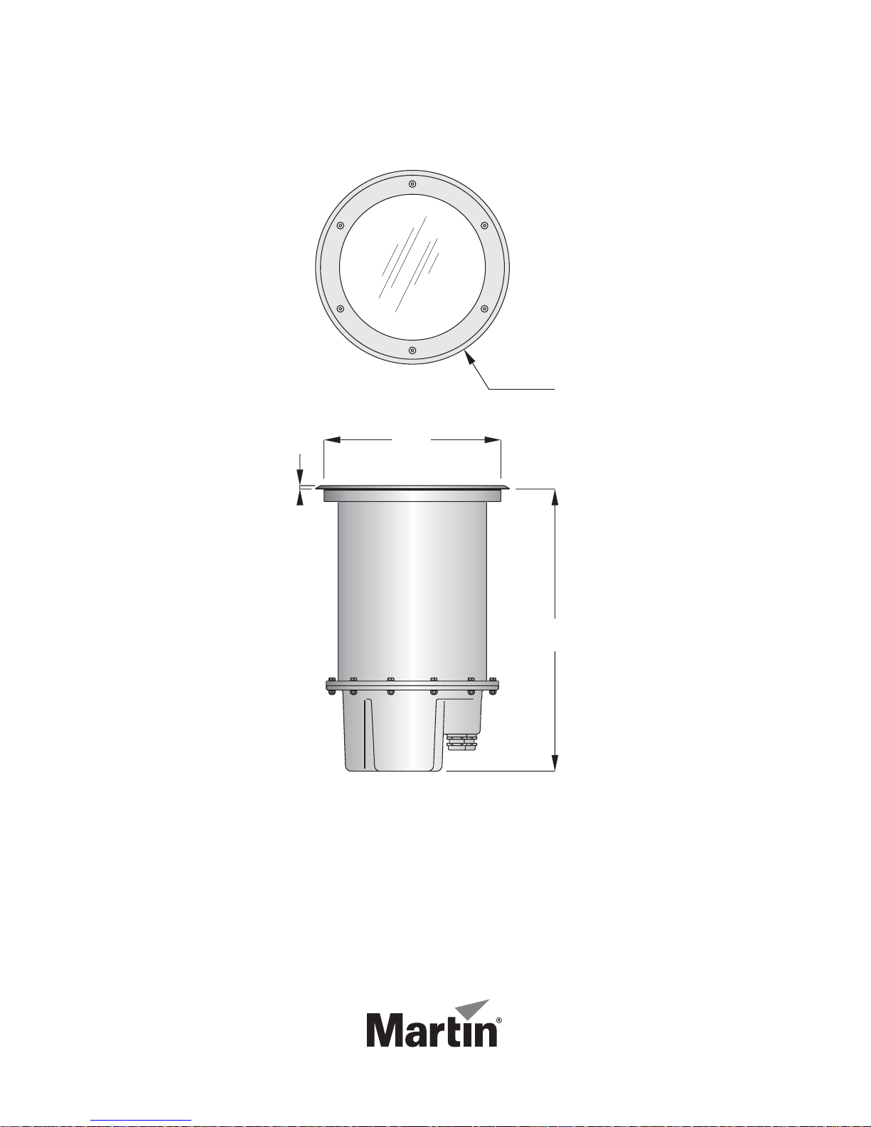
340
310
7
496
Dimensions
Measurements are in millimeters
© 2004-2008 Martin Professional A/S. Information subject to change without notice. Martin
Professional A/S and all affiliated companies disclaim liability for any injury, damage, direct or
indirect loss, consequential or economic loss or any other loss occasioned by the use of, inabil-
ity to use or reliance on the information contained in this manual. The Martin logo, the Martin
name and all other trademarks in this document pertaining to services or products by Martin
Professional A/S or its affiliates and subsidiaries are trademarks owned or licensed by Martin
Professional A/S or its affiliates or subsidiaries.
P/N 35000153, Rev C
Page 3

Section 1. Getting started . . . . . . . . . . . . . . . . . . . . . . . . . . . . . . . . . . . . . . 7
Introduction. . . . . . . . . . . . . . . . . . . . . . . . . . . . . . . . . . . . . . . . . . . . . . . 7
Inground 200 model range. . . . . . . . . . . . . . . . . . . . . . . . . . . . . . . . . . 7
Optics and accessories . . . . . . . . . . . . . . . . . . . . . . . . . . . . . . . . . . . . 7
Mains power options . . . . . . . . . . . . . . . . . . . . . . . . . . . . . . . . . . . . . . 8
Included items . . . . . . . . . . . . . . . . . . . . . . . . . . . . . . . . . . . . . . . . . . . 8
Safety information . . . . . . . . . . . . . . . . . . . . . . . . . . . . . . . . . . . . . . . . . 8
General operation . . . . . . . . . . . . . . . . . . . . . . . . . . . . . . . . . . . . . . . . 10
General guidelines. . . . . . . . . . . . . . . . . . . . . . . . . . . . . . . . . . . . . . . 10
Understanding shows and scenes. . . . . . . . . . . . . . . . . . . . . . . . . . . 10
Powering on for the first time. . . . . . . . . . . . . . . . . . . . . . . . . . . . . . . 11
Control and programming options . . . . . . . . . . . . . . . . . . . . . . . . . . . 11
Initial configuration for use. . . . . . . . . . . . . . . . . . . . . . . . . . . . . . . . . 12
Defining fixture settings using MUM . . . . . . . . . . . . . . . . . . . . . . . . . 14
Defining fixture settings using an MP-2 . . . . . . . . . . . . . . . . . . . . . . . 17
Section 2. Stand-Alone operation . . . . . . . . . . . . . . . . . . . . . . . . . . . . . . 21
Stand-alone programming overview. . . . . . . . . . . . . . . . . . . . . . . . 21
About scene timing . . . . . . . . . . . . . . . . . . . . . . . . . . . . . . . . . . . . . . 22
Synchronizing scene changes for multiple fixtures . . . . . . . . . . . . . . 22
Programming methods. . . . . . . . . . . . . . . . . . . . . . . . . . . . . . . . . . . . 23
Programming from a PC using MUM . . . . . . . . . . . . . . . . . . . . . . . 23
Getting started with MUM . . . . . . . . . . . . . . . . . . . . . . . . . . . . . . . . . 24
Stand-Alone Settings. . . . . . . . . . . . . . . . . . . . . . . . . . . . . . . . . . . . . 24
Programming effects in scenes . . . . . . . . . . . . . . . . . . . . . . . . . . . . . 26
Programming the same stand-alone show on multiple fixtures. . . . . 28
Programming using an MP-2 Uploader . . . . . . . . . . . . . . . . . . . . . 29
Getting started . . . . . . . . . . . . . . . . . . . . . . . . . . . . . . . . . . . . . . . . . . 29
Selecting fixtures to program. . . . . . . . . . . . . . . . . . . . . . . . . . . . . . . 30
Enabling or disabling stand-alone mode . . . . . . . . . . . . . . . . . . . . . . 31
Synchronizing scene changes for multiple fixtures . . . . . . . . . . . . . . 31
Automatically triggering stand-alone operation . . . . . . . . . . . . . . . . . 33
Programming effects in scenes . . . . . . . . . . . . . . . . . . . . . . . . . . . . . 33
Disconnecting the MP-2 Uploader. . . . . . . . . . . . . . . . . . . . . . . . . . . 35
Stand-Alone show playback . . . . . . . . . . . . . . . . . . . . . . . . . . . . . . . 35
Starting show playback automatically at fixture power-on. . . . . . . . . 35
Scene execution using the optional MC-X. . . . . . . . . . . . . . . . . . . . . 35
Page 4

DMX controller override during stand-alone show playback . . . . . . . 36
Synchronous triggering during Stand-Alone operation . . . . . . 37
Section 3. DMX control. . . . . . . . . . . . . . . . . . . . . . . . . . . . . . . . . . . . . . . . 39
DMX Controller operation . . . . . . . . . . . . . . . . . . . . . . . . . . . . . . . . . 39
Lamp control . . . . . . . . . . . . . . . . . . . . . . . . . . . . . . . . . . . . . . . . . . . 39
Effects . . . . . . . . . . . . . . . . . . . . . . . . . . . . . . . . . . . . . . . . . . . . . . . . 40
Section 4. Optics . . . . . . . . . . . . . . . . . . . . . . . . . . . . . . . . . . . . . . . . . . . . . 41
Color matching with other fixtures . . . . . . . . . . . . . . . . . . . . . . . . . 41
Section 5. Service and troubleshooting. . . . . . . . . . . . . . . . . . . . . . . . . 43
Service procedures . . . . . . . . . . . . . . . . . . . . . . . . . . . . . . . . . . . . . . . 43
Clearing excess humidity. . . . . . . . . . . . . . . . . . . . . . . . . . . . . . . . . . 44
Cleaning. . . . . . . . . . . . . . . . . . . . . . . . . . . . . . . . . . . . . . . . . . . . . . . 44
Seals . . . . . . . . . . . . . . . . . . . . . . . . . . . . . . . . . . . . . . . . . . . . . . . . . 45
Component removal & reinstallation . . . . . . . . . . . . . . . . . . . . . . . 46
Set-up and adjustment . . . . . . . . . . . . . . . . . . . . . . . . . . . . . . . . . . . . 55
Beam adjustment. . . . . . . . . . . . . . . . . . . . . . . . . . . . . . . . . . . . . . . . 55
Firmware updates . . . . . . . . . . . . . . . . . . . . . . . . . . . . . . . . . . . . . . . . 57
Printed circuit board layout. . . . . . . . . . . . . . . . . . . . . . . . . . . . . . . . 60
Troubleshooting. . . . . . . . . . . . . . . . . . . . . . . . . . . . . . . . . . . . . . . . . . 61
Section 6. Reference . . . . . . . . . . . . . . . . . . . . . . . . . . . . . . . . . . . . . . . . . . 63
MP-2 control menu structure . . . . . . . . . . . . . . . . . . . . . . . . . . . . . . 63
DMX protocol: Inground 200 CMY. . . . . . . . . . . . . . . . . . . . . . . . . . 66
Specifications: Inground 200 CMY . . . . . . . . . . . . . . . . . . . . . . . . . 67
Ordering information. . . . . . . . . . . . . . . . . . . . . . . . . . . . . . . . . . . . . . 70
Page 5

S
ECTION
1. G
1. Introduction
Thank you for selecting the Martin™ Inground 200™ Full Spectrum CMY,
an intelligent 150 watt uplight designed for permanent burial installation.
This User Manual contains details of how to operate and service this fixture.
For details of installing the Inground 200 CMY, please refer to the
Installation Guide shipped with the product. The most recent versions of the
Installation Guide and this User Manual are also available in the Product
Support area of the Martin website at http://www.martin.com
Inground 200 model range
ETTING STARTED
The Inground 200 is available in two models:
Inground 200 Single Color
The Inground 200 Single Color can be operated with or without a color filter
and can be manually dimmed, but it is not programmable and cannot be
controlled by DMX. A separate user manual, P/N 35000152, exists for this
product.
Inground 200 CMY
The Inground 200 Full Spectrum CMY offers seamless full spectrum colormixing, giving a virtually limitless color palette, and 0-100% intensity
control. It can be programmed to run synchronized stand-alone light shows
with pre-defined start/stop times using a Windows PC with Martin MUM™
software, or it can be operated using a DMX controller.
Optics and accessories
The following optional lenses are available for the Inground 200:
• Medium – 32° one-tenth peak angle
• Wide – 56° one-tenth peak angle
• Very wide – 98° one-tenth peak angle
•Wallwash
Introduction 5
Page 6

A range of accessories is available for the Inground 200. See “Ordering
information” on page 68. See also www.martin.com for the most recent
information.
Mains power options
Inground 200 Single Color and CMY models are both available in three
configurations to match local AC mains power:
• 210 V, 60 Hz (US model)
• 277 V, 60 Hz (US model)
• 230 V, 50 Hz (EU model)
Included items
The Inground 200 CMY is supplied with the following items:
• Philips CDM-SA/T 150W/942 lamp
• Silica gel sachet inside fixture for shipping (must be removed and
disposed of)
• Silica gel sachet packed separately in sealed aluminum bag (must be
fastened inside fixture and fixture closed within 20 minutes of opening
aluminum bag)
• DMX termination resistor
• 3 m (9.8 ft.) hard-wired power cable tail
• 3 m (9.8 ft.) hard-wired control data in/out cable tail
• Installation guide
• User manual
2. Safety information
Warning! This product is not for household use.
This product presents risks of lethal or severe injury due to fire, heat,
electric shock and lamp explosion.
Read this guide before operating the fixture, follow the safety precautions
listed below and observe all warnings in this guide and on the fixture.
If you have questions about how to operate or service the fixture safely,
please contact your Martin supplier or call th e Martin 24-hour service
hotline on +45 8740 0000, or in the USA on 1-888-tech-180.
6Safety information
Page 7

Guarding against electric shock
• Isolate the fixture from AC power before removing or installing the lamp,
fuses, or any part.
• Always ground (earth) the fixture electrically.
• Use only a source of AC power that complies with local building and
electrical codes and has both overload and ground-fault protection.
• Refer any service not described in this user manual to a Martin service
technician.
Lamp safety and eye protection
• Never operate the fixture with missing or damaged lenses and/or covers.
• Do not stare directly into the light. Never look at an exposed lamp while it
is lit.
• Wear safety glasses during beam adjustment.
• Use only approved lamp types (see “Source” on page 65).
• Replace the lamp if it becomes defective or worn out. The average life of
the Philips CDM-SA/T 150W/942 lamp supplied with the Inground 200
CMY is 9000 hours. If one of the approved alternative lamp types listed
under “Source” on page 65 is fitted, see the lamp supplier’s
documentation.
Guarding against burns and fire
• Allow the fixture to cool for at least 15 minutes after use before opening it
for service or adjustment.
• Wear heat-resistant safety gloves during beam adjustment.
• Never attempt to bypass the thermostatic switch or fuses. Always replace
defective fuses with ones o f the specifie d type and rating.
• Keep all combustib le materials (for e xample fabric, w ood, paper) at least 1
meter (39 inches) away fro m the fixture. Keep flammable materials well
away from the fixture.
• Ensure that litter, dry leaves or other combustible mater ials cannot
accumulate on or near the fixture.
• Prevent vehicles from being par ked over or near fixtures – including unlit
fixtures that may later be switched on.
• Do not illuminate surfaces within 0.5 meters (20 inches) of the fixture.
• Install the fixture outdoors or in a well ventilated area.
• The exterior of the fixture can become very hot, up to 80° C (176° F)
during normal operation. Ensure all local safety regulations and legal
requirements are observed, and take appropriate measures to warn or
restrict access.
• Do not modify the fixture or install other than genuine Mart in parts.
• Never place filters or other materials over the front glass.
Safety information 7
Page 8

Guarding against injury
• The front glass can be slippery, especially when we t. Ensure that
pedestrians are warned and/or kept away from the fixture.
• Block public access during service.
3. General operation
General guidelines
To avoid voltage drops which may result if many lamps strike at the same
time, there is a short delay before the lamp strikes after power-on.
For optimum lamp life and performance, allow the lamp to warm up fully for
five minutes before turning it off. Turn off lamp power whenever illumination
is not required for periods of one hour or more. Fixture power may remain
on when not in use.
When the temperature is expected to fall below freezing, leave the fixture
powered on when not in use to keep the electronics warm. The lamp,
however, may be switched off.
Understanding shows and scenes
If you are not familiar with programmable lighting, it will help you follow the
rest of this manual if you understand the concept of scenes and shows.
A scene is an effect that consists of a certain color displayed at a certain
intensity. A show, or program, is a sequence of scenes which can be
repeated again and again, if desired.
8 General operation
Page 9

Scenes consist of a Fade period
Wait
Wait
Wait
S
c
e
n
e
1
S
c
e
n
e
2
S
c
e
n
e
3
during which lighting fixtures
change to the desired effect, and
Fade
a Wait period, during which
fixtures continue to display the
desired effect.
The example on the right is a
3
e
n
e
c
S
lighting show consisting of 3
scenes. These 3 scenes could for
example be:
Fade
Fade
1. 30 seconds fade from blackout
e
n
to 40 seconds of 100%
e
2
intensity red light.
2. 30 seconds fade to 30 seconds
of 50% intensity blue light.
3. 20 seconds fade to 120 seconds of 80% intensity white light.
c
Fade
Fade
S
Fade
S
c
e
n
e
1
Powering on for the first time
When the Inground 200 CMY is connected to power for the first time, it will
start running a factory-set light show to test the fixture. It will continue to run
this test show until a new show is programmed into it, or until it receives
DMX commands.
Initial test show
The Inground 200 CMY is pre-programmed with 5 scenes to verify that the
CMY flags and the dimmer are working correctly.
1. White 100% intensity.
2. Cyan 100% intensity.
3. Magenta 100% intensity.
4. Yellow 100% intensity.
5. White 0% intensity (no light).
Control and programming options
The Inground 200 CMY can receive control and programming data via two
inputs:
• via the RJ45 service connector on the lamp modul e under the front glass
and lens
• via the DMX control data link.
General operation 9
Page 10

The RJ45 service connector has priority. This means that while data is
being received via the service connector, the fixture ignores any data
received via the data link.
Control and programming methods
The Inground 200 CMY can be programmed and controlled using one of the
methods listed below.
Stand-Alone programming
Using a PC with MUM software or a Martin MP-2 Uploader you can
program and store stand-alone light shows in individual fixtures:
1. Any fixture can be programmed to run its own independent stand-alone
show.
2. One fixture can be programmed to run a show and also send scenechange signals to any number of other fixtures via the data link, so that all
fixtures run a synchronized stand-alone show. Fixtures in synchronized
stand-alone shows can show identical or different scenes, but all fixtures
will change scene at the same time.
Stand-Alone programming is described in “Section 2. Stand-Alone
operation” on page 19.
DMX control
Using a DMX device to control fixtures via a data link, fixtures can be
controlled independently or in groups.
DMX control is described in “Section 3. DMX control” on page 37.
Initial configuration for use
Before the Inground 200 CMY can be programmed or controlled, certain
fixture settings need to be configured. This section describes how to
10 General operation
Page 11
configure these using either the Martin MUM™ (Multi-Utility Manager)
application or an MP-2 Uploader if available.
Martin MUM
application
Martin MP-2
Uploader
MUM is a Windows PC software application that must
be used in combination with a DABS1™ hardware
interface.
We recommend MUM because it provides an intuitive,
easy-to-use, graphic user interface.
MUM only allows you to connect to, and set up , one
fixture at a time.
For details of how to use MUM, see “Defining fixture
settings using MUM” on page 12.
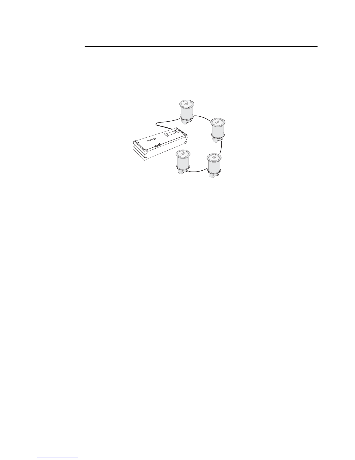
If you hav e an MP-2, it can be loaded with the Inground
200 CMY’s control software and connected to either a
data link or a single fixture, as illustrated below. The
MP-2 user manual contains full details of uploading
options and methods.
When working with multiple fixtures, an MP-2 allows
you to apply settings globally to multiple fixtures on a
data link.
The MP-2 provides a text-based interface an d the
fixtures do not provide feedback to th e uploader.
Therefore, the current settings of the fixture can only be
“read” by observing the behavior of the fixture.
For details of how to use the MP-2, see “Def ining fixture
settings using an MP-2” on page 15.
General operation 11
Page 12
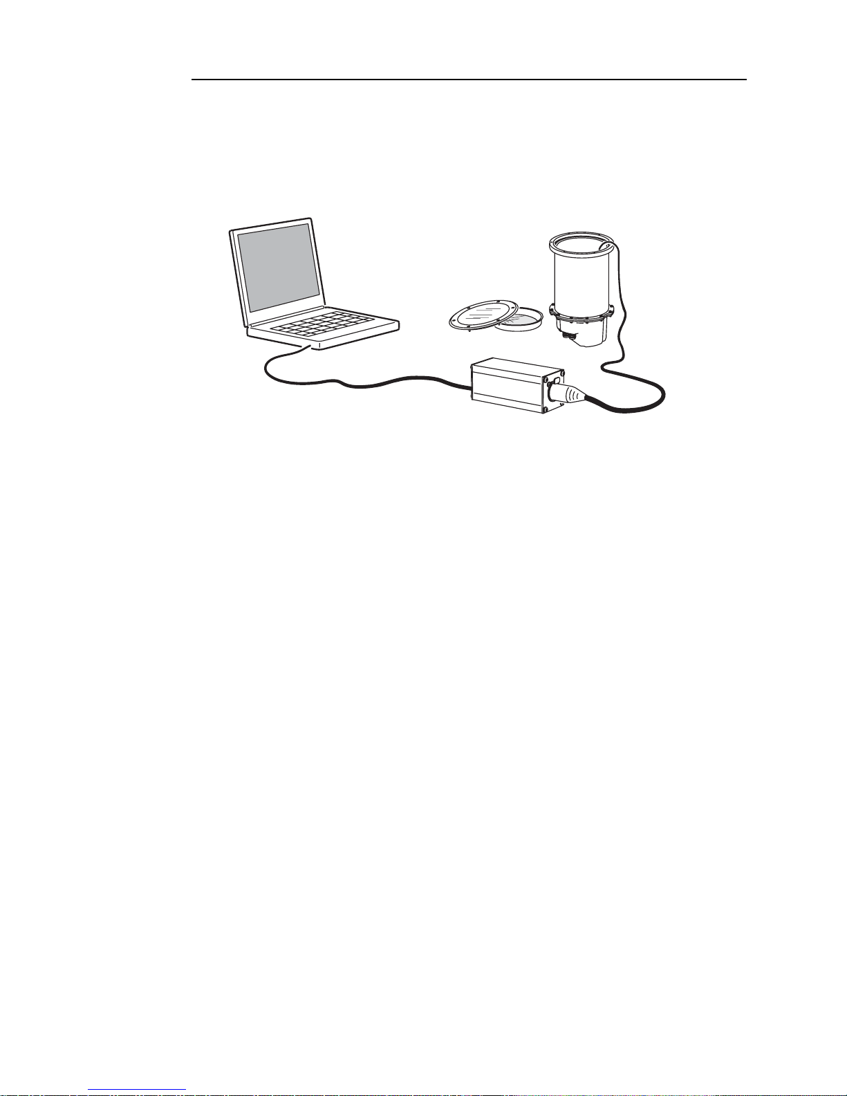
Defining fixture settings using MUM
Using MUM, you can connect to and set up one fixture at a time. Refer to
the MUM User Manual (available on the Martin website at
http://www.martin.com) for instructions on installing and starting the MUM
application.
PC
DABS1
MUM must be used with a DABS1 interface device. A complete package
containing MUM, the DABS1, documentation and all cables is available
from Martin dealers (P/N 90758090). The package includes an XLR-toRJ45 cable to connect the DABS1 to an Inground 200 CMY. This cable is
also available separately (P/N 11840087).
To get started:
Inground 200
1. Connect a PC to a DABS1 and connect the DABS1 to an Inground 200
CMY.
2. Power on the Inground 200 CMY and start the MUM application. MUM
will automatically detect an Inground 200 CMY if it is powered on and
connected. It will also retrieve the current settings from the fixture and
display them.
Setting the onboard clock
The Inground 200 CMY has a battery-operated 24-hour clock that can start
and stop stand-alone operation.
12 General operation
Page 13
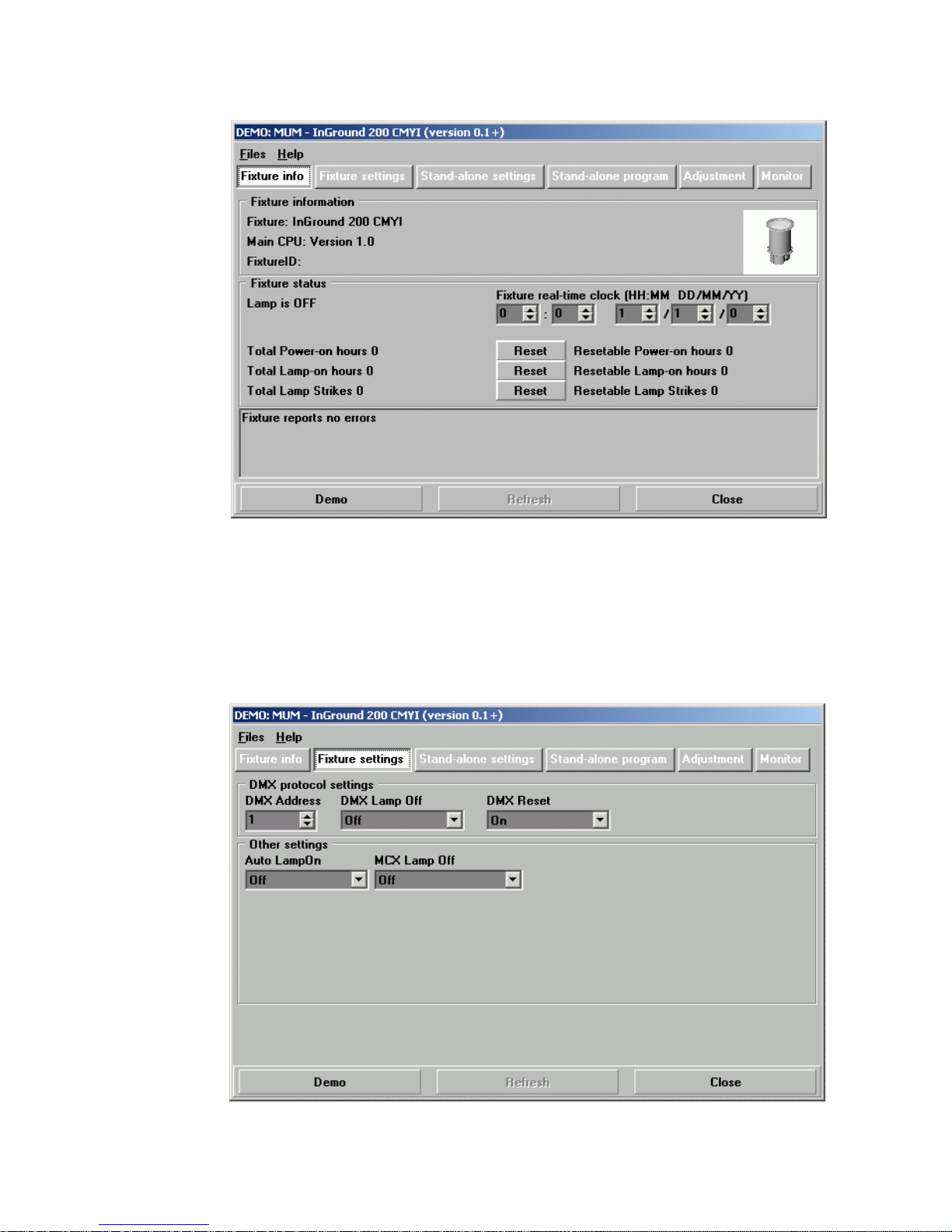
To set the clock:
1. in the main MUM window, click on the Fixture info button:
2. Using the two Fixture time spin buttons, set the fixture to the c urrent time
and date (expressed in the 24-hour clock in hours and minutes, then in
DD/MM/YY format). The time will be updated in the fixture in real-time.
Fixture settings
To set the additional fixture settings, click on the Fixture settings button:
General operation 13
Page 14

DMX address
If you are not familiar with the DMX lighting control prot ocol, it will help if y ou
read through “DMX Controller operation” on page 37.
The DMX address (also known as the control address, or start channel) is
the first channel used to receive instructions from the DMX controller. Each
fixture needs its own DMX address set, and uses this address (and control
channels immediately above this address) to receive instructions.
The Inground 200 CMY reads the data on its start channel and the next five
channels. If the control address is set to 100, the fixture uses channels 100,
101, 102, 103, 104 and 105. Channel 106 can be used as the DMX address
for the next fixture.
If two or more fixtures are set up with the same address, they will receive
the same instructions and should behave identically. Setting up identical
fixtures with the same address is a good tool for troubleshooting
unexpected behavior and an easy way to achieve synchronized action.
To set the DMX address use the DMX Address spin button. The fixture
address is updated in real time.
DMX Lamp Off
When the DMX Lamp Off personality is on (the default setting), lamp power
can be turned off from the controller by setting channel 1 to a decimal value
from 248 to 255.
DMX Reset
When the DMX Reset personality is on (the default setting), the fixture can
be reset from the controller by setting channel 1 to a decimal value from
208 to 217.
Auto Lamp On
When the Auto Lamp On personality is on, the fixture turns on the lamp
within 90 seconds of power on. When set to off (the default setting), a lampon command is required to turn on the lamp.
MC-X Lamp Off
By choosing the option MCX Preset 7 key from the MCX Lamp Off field,
you enable button 7 on an MC-X controller to be used to control the lamp off
function.
14 General operation
Page 15
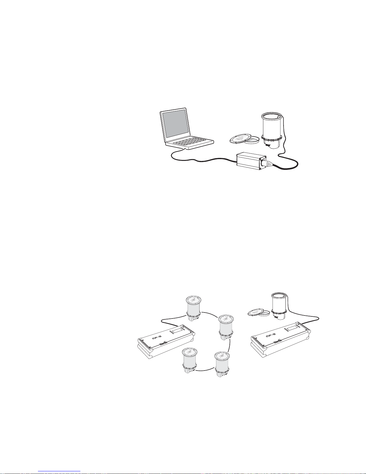
Defining fixture settings using an
MP-2
MP-2 Uploader users can apply settings globally to multiple fixtures on a
data link by loading the MP-2 with the Inground 200 CMY’s control software
and connecting it to a fixture or to the data link. The MP-2 Uploader user
manual contains instructions for this procedure.
Inground 200s
MP-2
The MP-2 has a text-based interface and does no t receive feedback from
fixtures. Therefore, the current settings of the fixture can only be “read” by
observing the behavior of the fixture.
Single-fixture and all-fixture modes
The MP-2 provides two ways to access fixtures: single-fixture mode and allfixtures mode. In single-fixture mode, the uploader communicates only with
the fixture at a designated address. In all-fixtures mode, the uploader
communicates with all fixtures of the same type to which it is connected.
Fixture-specific settings such as the control address should be made in
single-fixture mode. If no other fixtures are connected, however, then allfixtures mode may be used. Global settings are easiest to apply in allfixtures mode.
DMX address
The DMX address, also known as the control address, or start channel, is
the first channel used to receive instructions from an uploader. Each fixture
needs its own control address set, and uses this address and subsequent
control channels to receive instructions from an uploader or controller.
The Inground 200 CMY uses seven control channels. It re ads the data on
the start channel and the next six channels. If the control address is set to
100, the fixture uses channels 100, 101, 102, 103, 104, 105, and 106.
Channel 107 would be the control address for the next fixture.
If two or more fixtures are set up with the same address, they will receive
the same instructions and should behave identically. Setting up identical
General operation 15
Page 16

fixtures with the same address is a good tool for troubleshooting
unexpected behavior and an easy way to achieve synchronized action.
Important! When setting the address, either use single-fixture mode or isolate all
other fixtures from the uploader .
To set the control address:
1. Prepare an MP-2 or similar upload device as described in the uploader
user manual. If you know the address to which the fixture is currently set,
(i.e. the address to change from), connect the uploader to the data link
and use single-fixture mode. Otherwise, use all-fixtures mode and isolate
all other fixtures from the uploader. Apply power to the fixture.
2. If using single-fixture mode, scroll to the fixture’s current address and
press OK (in all-fixtures mode this step is not necessary).
3. Select
4. Scroll to the desired control address and press OK.
5. Press OK again to confirm and sav e the setting.
Fixture address from the Fixture Menu.
Personality settings
The following settings are av ailable in the uploader’s Personality menu
to modify fixture behavior.
DMX lamp off: When the DMX lamp off personality is on (the default
setting), lamp power can be turned off from the controller by setting channel
1 to a decimal value from 248 to 255.
DMX reset: When the DMX Reset personality is on (the default setting), the
fixture can be reset from the controller by setting channel 1 to a decimal
value from 208 to 217.
Auto lamp on: When the Auto lamp on personality is on (the default
setting), the fixture turns on the lamp within 90 seconds of power on. When
set to off, a lamp-on command from a DMX controller or an onboard timer is
required to turn on the lamp.
MC-X lamp off: When the MC-X Lamp-off personality is on (the default
setting), the lamp can be doused with a command from an MC-X controller.
To set a personality setting:
1. Prepare and connect an MP2 or similar upload device as described in the
device’s user manual. Apply power to the fixture.
2. Select single fixture mode to change a setting on a single fixture, or allfixtures mode to make global changes.
3. If using single-fixture mode, enter the fixture’s address.
4. Select
5. Select the desired personality and setting. (See “MP-2 control menu
structure” on page 61.) Press OK.
16 General operation
Personality from the fixture menu.
Page 17

Clock
The Inground 200 CMY has a battery operated 24-hour clock that can start
and stop stand-alone operation.
To set the clock:
1. Prepare and connect an upload device as described in the MP2 Uploader
manual. Apply power to the fixture.
2. Select all-fixtures mode.
3. Select
4. Select
5. Press OK.
6. Select
7. Press OK.
8. Press
Adjust -> Real time clock from the fixture menu.
Hour and scroll to the current hour.
Minute and scroll to the current minute.
Back to return to the main menu.
General operation 17
Page 18

18 General operation
Page 19

S
ECTION
2. S
TAND
-A
LONE
OPERATION
4. Stand-alone programming
overview
Stand-alone is a mode where the fixture executes color changes at set
intervals and speeds, at pre-defined periods during the day. The term
stand-alone is used to mean that the Inground 200 CMY is not connected to
a control device, but is pre-pro grammed with a series of up to 20 scenes
that play continuously in a loop.
‘Stand-alone operation’ involves:
• a single fixture running independently, or
• multiple fixtures running synchronously.
For multiple fixtures to run synchronously, one ‘master’ fixture must send
trigger signals to the other ‘slave’ fixtures via a DMX control data link. The
slave fixtures must all be programmed individu ally with shows, but each
scene in their shows is started by a trigger signal from the master fixture.
An Inground 200 CMY running a pre-programmed show can perform
synchronized scene changes with up to 31 other Martin Architectural
fixtures of the following types:
• Inground 200™ 6 Color
• Inground 200™ CMY
• Exterior 200™
• Exterior 600™
• Exterior 1200™ Wash
• Exterior 1200™ Image Projector
• Cyclo™ DMX models including Cyclo IP65 DMX
• FiberSource™ CMY150
• Imager™ series
• Alien 02™ series
• MiniMAC™ Maestro
• Exterior 200™ LED
More fixtures can be added to an installation by using one or more Martin
RS-485 Opto-Splitters. This small DMX amplifier will allow up to 4 additional
branches to be added to a data link, with 32 fixtures possible on each
Stand-alone programming overview 19
Page 20

branch. Full product details are available in the Products area of the Martin
Wait
Wait
Wait
S
c
e
n
e
1
S
c
e
n
e
2
S
c
e
n
e
3
website at http://www.martin.com
About scene timing
Each scene in a show has two parts:
1. a dynamic part - the fade - during which effects move to the scene’s
programmed positions
2. a static part - the wait - where
effects do not change.
The duration of the fade and wait is
programmed individually for each
scene. The fade and w ait times can
be between 0 seconds - 18 hours.
The total time it takes a scene to
ex ecute is the fade time plus the
wait time.
When operating multiple fixtures
synchronously, the wait time is
determined by the master fixture.
Slave fixtures f ade at their own rate
and then remain in the “wait” state
until they receive a “start scene” or “start show” trigger from the master.
3
e
n
e
c
S
Fade
Fade
Fade
S
Fade
c
e
n
e
1
Fade
Fade
S
c
e
n
e
2
When programming in synchronous triggering situ ations, you can make life
much easier if you make sure that:
1. Every fixture has the same number of scen es.
2. Respective scene times are a few seconds longer on the master fixture
than on the slave fixtures.
The rules used in the master/slave algorithm are detailed in “Synchronous
triggering during Stand-Alone operation” on page 35.
Synchronizing scene changes for
multiple fixtures
If you are running multiple Inground 200 CMYs on a data link, it is possible
to synchronize scene changes.
Note: Each individual fixture must be programmed with a show. The only
commands that are transmitted by the master fixture are scene change
commands. No data about the look of the scene is transmitted between
fixtures.
20 Stand-alone programming overview
Page 21

Programming methods
The Inground 200 CMY provides two stand-alone programming methods;
using:
1. the Martin MUM application on a Windows PC (recommended because it
provides an intuitive, easy-to-use, graphic user interface), or
2. an MP-2 Upload device, if available. See “Programming using an MP-2
Uploader” on page 27.
If you are programming a group of fixtures to perform the same scenes with
synchronized triggering then we recommend that you either:
1. Use MUM to program fixture settings and a show on a single fixture,
download and save the fixture memory to a file on your PC using MUM’s
Files menu, and then upload this file to each subsequent fixture that you
connect to, or
2. Use an MP-2 Uploader, if available, to program the same show on all the
fixtures on the network simultaneously (you can then assign their
individual DMX address afterwards).
5. Programming from a PC
using MUM
The programming of scenes, and setting up of master/slave relationships,
can be performed from a personal computer running the MUM application.
The PC must be connected to a fixture via a DABS1 adaptor. The PC is
used to program the stand-alone settings for that fixture, and then removed.
When this fixture is subsequently switched on, it can automatically run the
scenes in its show in a loop for two periods in each 24 hour period.
PC
DABS1
If you are not familiar with the use of MUM, it is recommended that you
familiarize yourself with it by reading the MUM user manual.
Inground 200
Programming from a PC using MUM 21
Page 22
Getting started with MUM
To get started:
1. Connect a DABS1 adaptor to your PC and an Inground 200 CMY using
the cables supplied in the MUM/DABS1 package. Replacement cables
are available from your Martin dealer.
2. Power on the Inground 200 CMY and start the MUM application. The
application will automatically detect an Inground 200 CMY if it is
powered-on and connected to your computer via a DABS1 adaptor . It will
also retrieve the current settings on the fixture and display them.
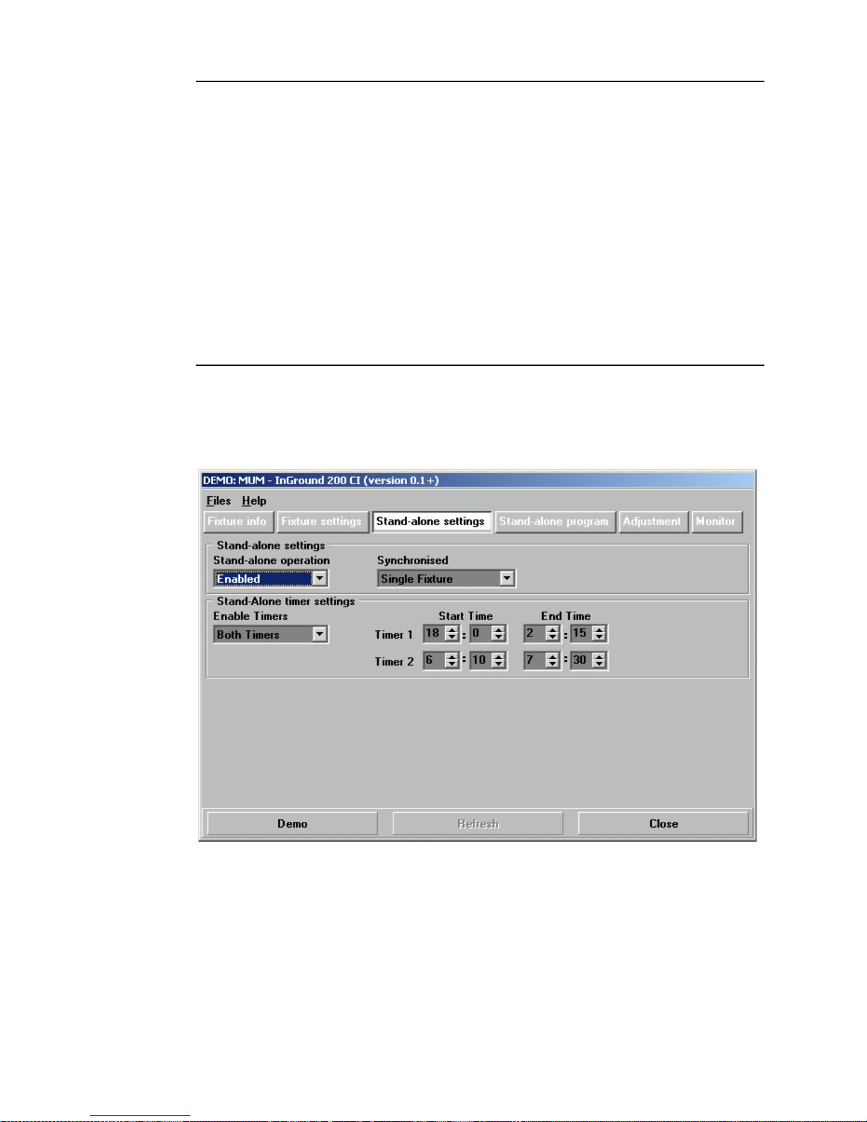
Stand-Alone Settings
The fixture needs to be configured to know if and when to activate a standalone show:
Click Stand-alone setting s to display the following window.
The following options are available:
Stand-alone
operation
22 Programming from a PC using MUM
Enables or disables stand-alone operation.
Page 23

Synchronized Specifies if the fixture operates as a:
• Single Fixture (runs independently of any
other fixtures)
• Master (triggers other fixtures) or
• Synchronized (slave fixture, receives trigger
signals from a master fixture).
Note: No more than one fixture may operate as
master. Any fixture on the DMX control link, however,
regardless of its position, may be the master. All other
fixtures must be set as slave fixtures by setting them
to Synchronized.
Stand-alone
timer settings
Enables timer 1 only, timer 2 only, or both timers (see
“Automatically triggering stand-alone operation” on
page 31)
Synchronizing shows on multiple fixtures
To synchronize scene changes, you need to set up o ne ‘master’ fixture to
trigger show star ts and scene changes in the other ‘slave’ fixtures. Each
slave fixture needs to have its own show programmed. The master fixture
triggers the slave fixtures’ show starts and scene changes in a cycle in time
with its own show.
Each slave fixture will run its programmed show in a loop, changing scene
when it receiv es a trigger from th e master fixture that tells it to go to a scene
number. When the master fixture finishes its own show, it sends a ‘go to
scene 1’ trigger that causes the slave fixtures to start their shows again
from scene 1.
Note: Each individual fixture must be programmed with its own show – the
master fixture only sends signals specifying the current scene number. No
data about the appearance of the scene is transmitted between fixtures.
Setting stand-alone operation with the
onboard clock
Stand-alone operation can be set for one or two periods during a 24 hour
period, using the built-in timers.
Note: If you are using a master and slave configuration, all fixture timers
must be set to switch fixtures on and off at the same times.
1. First set the correct time. See “Setting the onboard clock” on page 12.
Programming from a PC using MUM 23
Page 24

2. Set Enable Timers to one or two timers depending on whether you want
one or two periods of operation in each 24 hour period.
3. Then set the desired Start Time and End Time for each timer you have
enabled.
4. Select Enabled in the Stand-alone operat io n drop-down menu.
5. Remember to select Single Fixture, Master or Synchronized in the
Synchronized drop-down menu
Programming effects in scenes
The programming of light effects is performed using the Stand-alone
program controls.
24 Programming from a PC using MUM
Page 25

Inground 200 CMY stand-alone options
Click on the Stand-alone program button to open the programming
window:
The following options are available:
Intensity Sets dimmer level.
Cyan
Magenta
Yellow
Scene fade
time
Scene wait
time
Selects color by CMY levels.
The fade time, which can be between 0 seconds to 18
hours, is the time it takes to change from one color to
another.
This is the duration a color is applied. A wait time can be
between 0 seconds and 18 hours. If wait times are set to
0 seconds, colors will change continuously .
Master/slave fade and wait times
When operating multiple fixtures in synchronized-triggering mode, slave
fixtures fade and wait according to the programmed fade and wait times for
the scene they are running. Once a slave fixture’s programmed wait time is
over, the slave fixture remains in wait mode until it receives a trigger from
the master fixture telling it to go to another scene. If the slave fixture’s wait
time is not over, it will not accept ‘go to scene number XX’ commands from
the master fixture.
Therefore, when programming a master fixture, keep in mind that its total
scene times should be equal to or longer than the fade times of the other
fixtures. You will get unpredictable results if, for example, a scene is
Programming from a PC using MUM 25
Page 26

programmed in the master to last 10 seconds and in other fixtures to fade
for 15 seconds (if necessary, see “Synchronous triggering during Stand-
Alone operation” on page 35 for a more detailed explanation).
Scene management
Once you hav e specified a mix of effects, you can store the scene using the
buttons available in the main MUM window:
Store scene Save settin gs in the current scene.
Add scene Save settings in a new scene at the end of the
sequence.
Insert scene Save settings in a new scene before the current
scene, which mo ves up a number. Tip: Think of the
Add and Insert commands as Sav e commands, to be
used as the last step after programming all effects.
Delete scene Remove the cur rent scene from memory. Scenes
above the deleted scene move down a number.
Next scene Step to the next scene.
Previous
scene
Delete all Remove all scenes from the fixture memory.
Run program Run the scenes in the current programmed show.
When the show is run, scenes execu te in a continuous, ascending loop.
Note: If a slave fixt ure ha s:
• Fewer scenes than the master fixture, it will run these in a cycle
continuously until the master fixture signals that the show should star t
from the beginning again.
• More scenes than the master fixture, then the additional scenes will never
run, because the show will reset to the first scene when the master starts
its show from the beginning.
Step to the previous scene.
Programming the same stand-alone
show on multiple fixtures
Although you can only connect to and program a single fixture at a time
using the MUM application, you can use it to “copy” settings and shows
from one fixture to another. To do this, progr am a single fixture, then use the
commands in MUM’s Files menu to download and save the fixture settings
to a file on your PC. You can then upload the fixture settings and standalone show to each subsequent fixture that you connect to. This short-cut is
useful if you have a group of fixtures that will r un the same stand-alone
26 Programming from a PC using MUM
Page 27

show . If y ou cop y all settings using this method, remember to set one fixture
to master and the rest to synchronized.
6. Programming using an
MP-2 Uploader
The programming of scenes, and setting up of master/slave relationships,
can be performed using a Martin MP-2 Uploader, if available. The uploader
is connected to the fixture, used to program the stand-alone settings for that
fixture (or all the fixtures connected to that fixture by data link), and then
removed. When you po wer fixtures on, they can then automatically run their
programmed scenes at the times you specify.
To summarize, you can use the MP-2 Uploader to program:
• Individual fixtures, one at a time.
• The same show in multiple fixtures that are linked with data cables.
• Individual shows in multiple fixtures that are linked with data cables.
If you are not familiar with the use of the MP-2, it is recommended that you
familiarize yourself with it using the MP-2 Uploader manual.
You can find an overview of the functions and commands available in the
MP-2 in “MP-2 control menu structure” on page 61.
Getting started
An uploader can be connected either:
• via the DMX link
• via the RJ45 service connector sock et under the front glass and lens (see
“Removing the front glass and lens” on page 44). To connect an MP-2 to
Programming using an MP-2 Uploader 27
Page 28

the service connector you will need a 3-pin male XLR-to-RJ45 cable
(available fro m your Martin dealer: P/N 11840087).
Inground 200
Inground 200s
MP-2
1. Plug either the fixture’s or the data link’s, data-input cable into the 3-pin
female XLR “DMX/RS-485 OUT” socke t on the MP-2.
2. Apply power to the fixture and the MP-2.
3. Select
4. Select
to the firmware version that is loaded in the fixture.
5. Select
and select the desired menu item. For further guidance see the following
sections.
Read Memory Card from the MP-2 menu.
NEG VX.X.X. (Note that X.X.X is the number that corresponds
Fixture menu. Then use the keys on the uploader to navigate
MP-2
Selecting fixtures to program
Before you select a fixture to program, its control address must have been
set. If you hav e not ye t done so, follow the instructions described in “DMX
address” on page 15.
You have the option of programing all the Inground 200 CMYs on a data
link, or an individual Inground 200 CMY. Fixture-specific settings such as
the control address should be made in single-fixture mode. If no other
fixtures are connected, however, then all-fixtures mode may be used.
Global settings are easiest in all-fixtures mode. For example, it can be a
good idea to program the time into all fixtures simultaneously, while scenes
can be programmed int o fi xtu re s indi vi d ua ll y.
Note: It is important that all the fixtures have the same software version, or
the results will be unpredictable. For more infor m ation see “Firmware
updates” on page 55.
Selecting a single fixture
To program a single fixture:
28 Programming using an MP-2 Uploader
Page 29

1. Select Single address from the Fixture menu.
2. Select a start address that corresponds to the fixture that you want to
program using the arrows.
As you scroll through the start addresses, watch for a reaction from the
fixture you want to program. Make sure you select the star t address of
this fixture, i.e. the lowest DMX channel the fixture uses, and not one of
the fixture’s other DMX channels.
3. Select
OK.
Selecting all fixtures on a data link
To program all fixtures on the data link simultaneously, select All
addresses
from the Fixture menu.
Enabling or disabling stand-alone
mode
To:
• Disable stand-alone mode, select
and then
• Enable stand-alone mode, select Stand alone, then Enable SA,
and then
When stand-alone mode is enabled, fixtures enter stand-alone mode each
time power is applied. Stand-alone mode can be disabled temporarily by:
Off.
On.
Stand alone, then Enable SA,
• Turning the fixture off.
• Connecting a controller and sending control signals.
Synchronizing scene changes for
multiple fixtures
If you are running more than one Inground 200 CMYs on a data link, it is
possible to synchronize scene changes. Read this section if this applies in
your case.
To synchronize scene changes, you need to set up one ‘master’ fixtu re to
trigger show star ts and scene changes in the other ‘slave’ fixtures. Each
slave fixture needs to have its own show programmed. The master fixture
triggers the slave fixtures’ show starts and scene changes in a cycle in time
with its own show.
Each slave fixture will run its programmed show in a loop, changing scene
when it receiv es a trigger from th e master fixture that tells it to go to a scene
Programming using an MP-2 Uploader 29
Page 30

number. When the master fixture finishes its own show, it sends a ‘ go to
scene 1’ trigger that causes the slave fixtures to start their shows again
from scene 1.
Note: Each individual fixture must be programmed with its own show – the
master fixture only sends signals specifying the current scene number. No
data about the appearance of the scene is transmitted between fixtures.
Setting synchronized triggering options
1. Scroll to Stand Alone in the top level of the menus on the control
panel and press [enter].
2. Scroll to
3. Select:
Single fixture
Master
Synchronized
4. Press [enter].
SA Execution and press [enter].
If the fixture will operate in isolation (with no
synchronous triggering). This is the factory
default setting.
If the fixture will send scene triggering signals to
the other fixtures on the data link.
If the fixture should operate in slave mode and
“listen” for scene trigger signals on the data link.
Defining a master fixture
No more than one fixture may be the master. Any fixture on the link,
however, regardless of its position, may be the master.
1. From the
2. Select Master. This designates the fixture as the master fixture and
causes it to transmit synchronization signals to the slave fixtures when it
runs its show.
Stand alone menu, select SA Execution.
Defining slave fixtures
All other fixtures must be set as slave fixtures:
1. From the
2. Select
which will respond to synchronization signals received from the master
fixture.
30 Programming using an MP-2 Uploader
Stand alone menu, select SA Execution.
Synchronized. This designates the fixture as a slave fixture
Page 31

Automatically triggering stand-alone
operation
Stand-alone operation can be set for one or two periods during a 24 hour
period using the built-in clock.
Setting a timer trigger
First set the correct time. See “Clock” on page 17.
You can set timer operation for a single period, or for two periods, for
example, one period in the morning, and one period in the evening. To set
the timer for a single period:
1. Select Stand alone from the Fixture menu.
2. Select
3. Select
Select OK.
4. Select
OK.
5. Select
6. Select
Select OK.
7. Select
OK.
8. Select
9. Select Enable and select the timer you want to activate (in this case,
Timer 1).
Timer, then Timer1.
Start, then Hour. Use the arrow keys to specify the start hour.
Minute. Use the arrow keys to specify the start minute. Select
Back.
Stop, then Hour. Use the arrow keys to specify the stop hour.
Minute. Use the arrow keys to specify the stop minute. Select
Back.
Programming effects in scenes
The programming of effects is performed using the stand alone Program
menu options, such as:
Intensity
Cyan
Magenta
Yellow
Fade time
Wait time
Programming using an MP-2 Uploader 31
Dimmer lev el.
Color
The fade time is the time it takes to change from one
color to another. A fade time can be between 0
seconds and 18 hours.
This is the duration a color is applied. A wait time can
be between 0 seconds and 18 hours.
Page 32

Master/slave fade and wait times
When operating multiple fixtures in synchronized-triggering mode, slave
fixtures fade and wait according to the programmed fade and wait times for
the scene they are running. Once a slave fixture’s programmed wait time is
over, the slave fixture remains in wait mode until it receives a trigger from
the master fixture telling it to go to another scene. If the slave fixture’s wait
time is not over, it will not accept ‘go to scene number XX’ commands from
the master fixture.
Therefore, when programming a master fixture, keep in mind that its total
scene times should be equal to or longer than the fade times of the other
fixtures. You will get unpredictable results if, for example, a scene is
programmed in the master to last 10 seconds and in other fixtures to fade
for 15 seconds (if necessary, see “Synchronous triggering during Stand-
Alone operation” on page 35 for a more detailed explanation).
Scene management
Once you hav e specified a mix of effects, you can store the scene using the
options available under the Program menu:
Store
scene
Add scene
Insert
scene
Delete
scene
Next scene
Previous
scene
Clear
scenes
Run
program
Save set ti n gs in th e current scene.
Save settings in a new scene at the end of the
sequence.
Save settings in a new scene before the current
scene, which mo ves up a number. Tip: Think of the
Add and Insert commands as Sav e commands, to be
used as the last step after programming all effects.
Remove the cur rent scene from memory. Scenes
above the deleted scene move down a number.
Step to the next scene.
Step to the previous scene.
Remove all scenes from the fixture memory.
Run the scenes in the current programmed show.
The only indication of what the current scene is comes from the behavior of
the fixture.
When the programmed show is run, scenes execute in a continuous,
ascending loop.
32 Programming using an MP-2 Uploader
Page 33

If a slave fixture has:
• Fewer scenes than the master fixture, it will run these in a cycle
continuously, until the master fixture signals that the show should start
from the beginning again.
• More scenes than the master fixture, then the additional scenes will never
run, because the show will reset to the first scene when the master starts
its show from the beginning.
Disconnecting the MP-2 Uploader
When all the settings have been made, disconnect the data input cable from
the MP-2.
7. Stand-Alone show playback
Starting show playback
automatically at fixture power-on
Execution of programmed scenes in a loop will start automatically when the
fixture is powered-on if stand-alone operation is enabled and the automatic
lamp-on function is enabled.
To check or define this function:
• If you are using MUM on a PC, se e “Stand-Alone Settings” on page 22
and “Auto Lamp On” on page 14.
• If you are using an MP-2 uploader, see “Enab ling or disabling stand-alone
mode” on page 29 and “Auto Lamp On” under “Personality settings” on
page 16.
Scene execution using the optional
MC-X
The MC-X is an optional remote control module that is available from
Martin. Once the remote controller is connected, 7 scenes can be
conv en i e ntly called up on the MC-X's buttons.
Stand-Alone show playback 33
Page 34

Enabling MC-X control
Using an MP-2
For each fixture:
1. Disable stand-alone operation on each fixture: select
Stand alone /
Enable SA / OFF and press [enter]. Press [menu] to exit the Stand
alone
2. Using the
set button 7 on the MC-X to control the lamp off function. See “MP-2
control menu structure” on page 61.
menu.
Personality / MC-X lamp off menu it is possible to
Using MUM
For each fixture:
1. Disable stand-alone operation. See “Stand-Alone Settings” on page 22,
under the chapter “Programming from a PC using MUM”.
2. Enable lamp-on from the MC-X. See “MC-X Lamp Off” on page 14 in the
section “Defining fixture settings using MUM”.
Connecting and using the MC-X Controller
1. Connect the MC-X controller to the Inground 200 CMY’s data network via
an XLR-to-RJ-45 adaptor. If multiple Inground 200 CMYs are connected,
plug the controller into the first fixture in the link.
2. To trigger scenes 00-06, press the numbered preset buttons 1 - 7 on the
MC-X.
3. To have each fixture run its own routine, press [Auto].
DMX controller override during
stand-alone show playback
If an Inground 200 CMY is connected to a DMX controller and receives
DMX signals during show playback, the Stand-Alone show will stop running
and the fixture will respond to the DMX controller. DMX signals always have
priority over the running of a Stand-Alone show.
34 Stand-Alone show playback
Page 35

8. Synchronous triggering
during Stand-Alone
operation
Note: This chapter details the rules that are used in Stand-Alone
synchronous triggering. It is not necessary to read this chapter unless
you require help with problem diagnosis or unless you otherwise need
a detailed understanding of the algorithm used for synchronous
triggering.
The rules are as follows:
1. Every fixture can have up to 20 on-board scenes with individual fade and
wait times.
2. Scenes are numbered from 0 to 19.
3. A scene contains a fade-section, followed by a wait-section.
4. When running “synchronous trig gering” one master Inground 200 CMY
issues commands to the other slave Inground 200 CMYs to “go to scene
xx”, where xx is the scene number that the master will execute next.
5. If a slave has fewer scenes than the master, it will derive which scene to
go to by dividing the number of the scene it has been commanded to go
to (scene 5, for example) by the total number of scenes that the slave
fixture has (4, for example) in whole numbers (no decimal places). In this
example 5 divided by 4 results in 1, with 1 remainder. This remainder will
be the number of the scene that the slave fixture starts - scene 1.
Generally though, when a slave fixture reaches its own last scene before
the master fixture, a “go to scene xx” message will result in the first scene
being played.
6. If a slave has more scenes than the master calls, the last scenes in the
slave will ne v er be ex ecuted, as is the case with scene S4 in the following
example.
F=fade, W=wait Timeline =>
M0 M1 M2 M3
Programmed in Master F W F W F W F W
S0 S1 S2 S3 S4
Programmed in Slave F W F W F W F W F W
Result M0 M1 M2 M3
FW FWF WFW
S0 S1 S2 S3
FW FW FW ----F W
Synchronous triggering during Stand-Alone operation 35
Page 36

7. A slave fixture will not listen for the next message from the master fixture
before it has finished its current scene. This may result in a slave fixture
skipping a scene if the slave has a longer scene time than the master.
Note that in the following example the scenes in the slave fixture run out
of their programmed sequence because scenes 0 and 2 on the slave are
longer than the corresponding scenes on the master.
M=master, S=slave
F=fade, W=wait Time >
Programmed M0 M1 M2
Master F W F W F W
S0 S1 S2
Slave F W F W F W
Result M0 M1 M2 M0 M1
Master F W F W F W F W F W
S0 S2 S1
Slave F W F W .. .. FW .. ..
36 Synchronous triggering during Stand-Alone operation
Page 37

S
ECTION
3. DMX
CONTROL
9. DMX Controller operation
DMX512 is a USITT standard protocol used to send instructions from a
DMX controller to lighting fixtures on a data link. A total of 512 control
channels are available in one DMX universe. The Inground 200 CMY uses
six DMX control channels.
This section describes how to operate the fixture with a standard DMX
controller. For use with the Martin MC-X controller, please see “Scene
execution using the optional MC-X” on page 33. See the DMX protocol
starting on page 64 for specific control values.
DMX control device
Important: If an Inground 200 CMY receives DMX signals during show playback,
the stand-alone show will stop running and the fixture will respond to
DMX control. DMX signals always have priority over stand-alone
operation.
Lamp control
The lamp can be turned on and off from the controller using the lamp-on
and lamp-off commands on channel 1. If the DMX Lamp-off personality
setting is set to off, the lamp cannot be turned off using DMX.
To have the lamp strike automatically at power-up, set the Automatic Lampon personality to on (see page 16). Striking many lamps simultaneously
can cause voltage drops, so lamps strike after a short random delay at
power-up.
Note: After being turned off, the lamp must cool for at least 8 minutes
before it can be turned back on.
DMX Controller operation 37
Page 38

Effects
The mechanical effects reset to their home positions when the fixture is
powered on. Effects can also be reset from the controller on channel 1. If
the DMX Reset personality is set to off, the fixture cannot be reset using
DMX.
Dimmer
The mechanical dimmer provides smooth, high resolution, full-range
dimming on channel 2.
CMY subtractive color mixing
The CMY color mixing system is based on cyan, magenta, and y ellow color
filters. A continuous range of colors may be achieved b y varying the amount
of each filter from 0 to 100% on channels 3, 4, and 5.
Note: Mixing 3 colors results in a loss of light - the light is blacked out when
all 3 colors are fully applied. For maximum brightness , mix only 2 colors at a
time.
If you have other types of fixture in th e same installation as Inground 200
CMY fixtures, refer to “Color matching with other fixtur es” on page 39.
Effect speed
The speed at which effects fade, that is, move from one position to another,
can be controlled in two ways known as tracking control and vector control.
You may switch between tracking and vector control, but you cannot use
both at the same time.
Tracking control is enabled by setting the speed channel 6 to a decimal
value from 0 to 2. Fades are then programmed using the controller’s crossfaders. The Inground 200 CMY has a digital filter algorithm that averages
several updates to ensure smooth movement.
Vector control provides a way to program fa des on controllers without cros sfaders and may provide smoother fades than tracking control with some
controllers, particularly on very slow fades. A vector speed is programmed
by setting the speed channel to a decimal value from 3 (fastest) to 245
(slowest). The speed setting applies to dimmer and color fades. When using
vector control, the controller cross-fade time, if available, must be set to 0.
38 DMX Controller operation
Page 39

S
ECTION
4. O
PTICS
10.Color matching with other
fixtures
If you are running Inground 200 CMY fixtures together with other Martin
Architectural fixtures that use different lamps with different color
temperatures, etc., colors will not match exactly when the same CMY
values are used on the different fixtures.
This applies to an Exterior 600 fitted with an MSD 575 lamp, for example.
Generally speaking, the:
• Higher color temperature MSD lamp used in the Exterior 600 will give
deeper colors in the cold colors of the spectr um.
• Lower color temperature CDM lamp used in the Inground 200 CMY will
give deeper colors in the warm colors of the spectrum.
The following table gives some approximate values for color matching:
Exterior 600
Color
White Magenta 25
White Open Cyan 74
Yellow Yellow 241
Magenta Magenta 100
Cyan Full cyan
Red Full magenta
Green Cyan 241
Blue Full cyan
(with MSD 575 lamp)
Yellow 44
Magenta 16
Yellow 68
Magenta 25
Yellow 44
Full yellow
Yellow 241
Full magenta
Inground 200 CMY
(with CDM lamp)
Open
Full yellow
Full magenta
Full cyan
Magenta 215
Full yellow
Full cyan
Full yellow
Cyan 255
Magenta 191
Color matching with other fixtures 39
Page 40

40 Color matching with other fixtures
Page 41

S
ECTION
5. S
ERVICE AND
TROUBLESHOOTING
11. Service procedures
This section describes service procedures that can be performed by the
user. Refer all service not described here to a qualified Martin Architectural
technician.
Warning! Isolate the fixture from power and allow to cool for at least 15
minutes before removing any cover.
Trim ring
Front glass with seal
Lens
Beam adjustment ring
Lamp module
Housing
PCB/power compartment
Service procedures 41
Page 42

Clearing excess humidity
Each time the Inground 200 CMY is opened, the silica gel anti-humidity
sachet fastened to the lamp module must be removed and a new item
fastened in its place (see “Anti-humidity sachet replacement” on page 45).
Excess humidity inside the fixture can be experienced in the following
situations:
• The installation well is waterlogged
• The trim ring and front glass are not sealed correctly on the top of the
housing.
• The anti-humidity sachet fastened to the lamp module is saturated or
missing.
Warning! If you clear excess humidity as described below:
• The exposed lamp and internals present a risk of electric shock,
burns and ultra-violet radiation. A hot discharge lamp is under
pressure and there is a risk of lamp explosion. Block public access,
wear safety glasses and heat-resistant gloves, handle the lamp
module with care, and do not look into the light beam.
• Choose dry weather.
• Ensure that no dust or objects enter the fixture while it is open.
If there is excess humidity in the Inground 200 CMY, condensation will
appear under the front glass. To eliminate excess humidity:
1. Chec k that the installation has adequate drainage and that the top glass
and trim ring are sealed correctly. Rectify any problems.
2. Install a new anti-humidity sachet and reinstall the front glass
immediately (new anti-humidity sachets are available from Martin
suppliers – see “Spare parts” on page 68).
Cleaning
Wash the front glass with a soft brush or sponge and a mild, non-abrasive
car washing detergent. Wipe off traces of detergent with a sponge or brush
soaked in clean water.
Do not use a hose or high-pressure spray equipment on the fixture. The
Inground 200 CMY is water-resistant, but is not designed for submerged
operation. Excessive use of water may flood the installation sleeve.
42 Service procedures
Page 43

Seals
To maintain the fixture’s resistance to dust and moisture, it is important that
you replace seals and covers carefully after removal.
The PCB/power compartment cover Allen screws must first be scre wed in
until they are finger-tight, and then given an extra 3/4 to one full turn. This
will ensure that seals are compressed by about one-third. When fitting the
front glass trim ring, use a torque driver and cross-tighten the screws
gradually to a torque of 6 Nm (4.4 ft.-lbs.).
Warning! Do not use silicone or any other kind of sealant on the front glass seal,
front glass, housing or trim ring. Doing so will invalidate the product
warranty.
The silicone seals should maintain their sealing ability for the life of the
fixture. However, when servicing the fixture, note the condition of the seals
and replace any seal that is cracked, torn, brittle, or inflexible. Replacement
seals may be ordered as follows:
Front glass seal ....................................................P/N 20600441
PCB/power compartment seal ..............................P/N 20600450
Service procedures 43
Page 44

12. Component removal &
reinstallation
Tasks such as beam adjustment and lamp replacement require the removal
and refitting of certain components. This section contains instructions for
these procedures.
Besides safety gloves and safety glasses, you will need a torque driver with
a range that includes 6 Nm (4.4 ft.-lbs.) as well as 4mm and 2.5mm Allen
bits for these procedures.
Warning! Danger of burns, electric shock and lamp explosion!
• These procedures must be carried out by authorized electrical
personnel and in clean, dry conditions only.
• Wear heat-resistant safety gloves and safety glasses throughout
these procedures.
• Do not look directly into the lamp.
• Make sure that nothing falls into the fixture while the front glass and
lens are removed.
Important! Any damaged seals or screws must be replaced with new items. Two
spare 4mm countersunk Allen screws for the trim ring are supplied
with the fixture.
The front glass seal, its seating surface in the housing, the front glass
and the trim ring must all be perfectly clean and dry during reinstallation to maintain a waterproof seal.
Do not use silicone or any other kind of sealant on the front glass seal,
front glass, housing or trim ring. Doing so will invalidate the product
warranty.
The anti-humidity sachet inside the fixture must be rene w ed eac h time
the fixture is opened for service.
Removing the front glass and lens
The front glass and lens must be removed for bea m adjustment and all
other service interventions.
To remove the front glass and lens:
1. Isolate the fixture from AC power and ensure that power cannot be
reapplied, even accidentally. Allow the fixture to cool for at least 15
minutes.
44 Component removal & reinstallation
Page 45

2. Brush or if possible vacuum sand, dirt, etc. away and clean the top of the
4mm
fixture and the surrounding area to ensure that dirt does not fall into the
fixture.
3. Remove the six countersunk 4mm Allen screws and lift the trim ring off
the fixture
4. Taking care to avoid damaging the seal, lift off the front glass and its seal.
5. The lens is under the front glass, resting on the beam adjustment ring on
top of the lamp module. Lift the lens out of the fixture.
6. If a light spill limiter ring (shading plate) and/or a louvered anti-glare plate
are installed under the lens, lift them out of the fixture.
Removing the lamp module
The lamp module must be removed for replacement of the anti-humidity
sachet, lamp replacement, and all other service interventions apart from
beam adjustment.
To remove the lamp module:
1. Remove the front glass and lens, then any shading pate and/or louvered
anti-glare plate fitted, noting the orientation of the louvered anti-glare
plate (see “Removing the front glass and lens” on page 44).
2. Do not loosen the beam adjustment screws and do not disturb the beam
adjustment settings, or the beam will have to be readjusted. Holding the
lamp module by the beam adjustment ring, gently lift the whole module
upwards until it is clear of the housing.
3. Note the positions of the lamp module wiring connectors, then disconnect
them and lift the lamp module away from the fixture.
Anti-humidity sachet replacement
Each time the Inground 200 is opened for service, or to clear excess
humidity at any time, the silica gel anti-humidity sachet fastened to the lamp
module inside the fixture must be removed and a new item fastened in its
place. The fixture must be closed within 20 minutes of opening the
aluminum bag holding the new anti-humidity sachet.
Component removal & reinstallation 45
Page 46

New anti-humidity sachets are available from Martin suppliers (see “Spare
parts” on page 68 for details).
To renew the anti-humidity sachet:
1. Remove the front glass, lens and lamp module (see “Remo ving the front
glass and lens” on page 44 and “Removing the lamp module” on page
45).
2. See illustration below. Cut the cable tie holding the silica gel anti-
humidity sachet to the side of the lamp module above the cooling fan
and remove the sachet.
Cooling fan
3. Remove a new anti-humidity sachet from its sealed aluminum packet
and fasten it with a cable tie in the place of the sachet you have
removed. You must now reinstall components and close the fixture within
20 minutes.
46 Component removal & reinstallation
Page 47

Lamp replacement
The Inground 200 CMY is supplied with a Philips CDM-SA/T 150W/942
discharge lamp.
The Inground 200 CMY may be used with the following lamp types:
Lamp Efficiency Color Temp. Average Life
Philips CDM-SA/T 150W/942 88 Lm/W 4200 K 9 000 hours
Philips CDM-T 150W/830 93 Lm/W 3000 K 12 000 hours
Osram HCI-T 150W/WDL* 97 Lm/W 3000 K 12 000 hours
Osram HCI-T 150W/NDL* 91 Lm/W 4200 K 12 000 hours
Table 1: Lamp specifications
*WDL = warm daylight, NDL = neutral daylight
If in any doubt about suitable lamp types, consult your Martin Architectural
dealer.
Important! Installing any other lamp type may damage the fixture.
Warning! Allow the fixture to cool for at least 15 minutes before removing the
front glass.
Component removal & reinstallation 47
Page 48

To replace the lamp:
2.5mm
1. Remove the front glass, lens and lamp module (see “Remo ving the front
glass and lens” on page 44 and “Removing the lamp module” on page
45).
2. Turn the lamp module upside down and loosen – but do not remove – the
three 2.5mm Allen screws on the lamp baseplate pillar bolts.
3. Turn the lamp baseplate anti-clockwise a few degrees to release it from
the three Allen screws, then gently lift the baseplate assembly off the
lamp module.
48 Component removal & reinstallation
Page 49

4. Remove the old lamp from the socket. Holding the new lamp by its
ceramic base - do not touch the glass bulb - insert it firmly and sq uarely
into the lamp socket. Clean the glass bulb with an alcohol wipe or a
clean, lint-free cloth wetted with 99.9% isopropyl alcohol.
5. Refit the lamp baseplate on the three pillar bolts, twisting clockwise to
locate it, and retighten the three Allen screws to secure it.
6. If no further service is required, fasten a new anti-humidity sachet to the
lamp module, then reinstall the lamp module, any shading or anti-glare
plates originally fitted, the lens and the front glass (see “Anti-humidity
sachet replacement” on page 45, “Reinstalling the lamp module” on page
51 and “Reinstalling the lens and front glass” on page 51).
Accessing the PCB/power module
If you need to perform a boot sector upload, you will need access to the
printed circuit board in the PCB/power compartment.
Removing the PCB/power module
1. Remove the front glass, lens and lamp module (see “Removing the front
glass and lens” on page 44 and “Removing the lamp module” on page
45).
2. The PCB/power compartment is the larger of the two compartments in
the bottom of the fixture. Note the positions of the connectors and
disconnect the connections to this compartment.
Component removal & reinstallation 49
Page 50

3. See illustration below. R emove the five 5mm Allen screws from the
PCB/power compartment cover plate.
4. Holding the cover plate by its wire service handle, lift it carefully upwards,
avoiding damage to the seal. The two PCBs and the power components
are mounted on the cover plate itself, forming the PCB/power module. Lift
this entire module carefully out of the fixture.
5. The PCB/power compartment and cable inlet compartment share one
seal. Check this seal for damage. If it is damaged or brittle, it must be
replaced with a new seal (availab le from your Martin Architectural dealer:
P/N: 20600450). Cable entry is sealed for life, so replacement of this seal
is the only reason ever to open the cable inlet compartment.
6. After service in the PCB/power compartment is completed, ensure that
the seal and mating surfaces in the PCB/power compartment cover plate
and housing are perfectly clean and dry.
Note: Do not apply silicone or any other type of sealant to the seal or
mating surfaces. Doing so will invalidate the product warranty.
7. Lower the PCB/power module carefully into place, being careful not to
damage the seal or trap wires.
8. Tighten the five PCB/power compartment cover plate Allen screws by
hand until they are finger tight. Then use an Allen key to further tighten
each screw by between three quarters of a turn and one full turn. Screws
will now be tight enough to achieve a waterproof seal.
Note: Do not overtighten, or you may damage the seal and invalidate the
product warranty.
50 Component removal & reinstallation
Page 51

9. If no further service is required, fasten a new anti-humidity sachet to the
lamp module, then reinstall all components as described in this chapter
before reapplying power.
Connecting lamp leads to the starter
If it ever becomes necessary to disconnect the lamp wiring harness from
the starter, make sure that the wires in the harness are reconnected to the
starter as follows:
• White wire with blue sleeve to screw terminal marked N
• White wire without sleeve to screw terminal marked LP
• Wire without insulation (bare copper) and ring terminal to chassis where
the ground (earth) wire was originally fastened.
Reinstalling the lamp module
1. Remove a new anti-humidity sachet from its sealed aluminum packet and
fasten it with a cable tie in the place of the existing sachet (see “Anti-
humidity sachet replacement” on page 45). You must now close the
fixture within 20 minutes.
2. Reconnect the lamp module wiring connectors.
3. Note the position of the screw in the lamp module seating in the housing.
Lower the lamp module into the housing, rotating it if necessary so that
the notch in the top of the lamp module engages with the screw. The
lamp module is now correctly oriented.
4. If beam settings have been disturbed, readjust the beam (see “Beam
adjustment” on page 53).
Reinstalling the lens and front glass
Important! Before reinstalling the lens and front glass, ensure that the anti-
humidity sachet fastened to the lamp mo dule has been replac ed with a
new item.
Replace any damaged seals or screws with new items.
The front glass seal, its seating surface in the housing, the front glass
and the trim ring must all be perfectly c lean and dry to maintain a
waterproof seal.
Inspect the front glass seal for signs of damage or deterioration before
refitting. Replacement front glasses and seals are available from
Martin Architectural dealers (standard front glass: P/N 41700007, front
glass seal: P/N 20600441).
Inspect the six countersunk Allen screws from the trim ring before
reuse. Threads must be clean and undamaged. Two spare screws are
Component removal & reinstallation 51
Page 52

supplied with the fixture. Replacement screws are available from
A
B
C
D
E
F
Martin Architectural dealers (P/N: 08111314)
Do not use silicone or any other kind of sealant on the front glass seal,
front glass, housing or trim ring. Doing so will invalidate the product
warranty.
1. Inspect the front glass seal for damage before refitting. Replacement
front glasses and seals are available from Martin dealers (standard front
glass: p/n 41700007, front glass seal: p/n 20600441).
2. Reinstall any shading plates and louvered anti-glare plates that were
originally installed.
3. Refit the lens by lowering it into the housing, rotating the lens if
necessary so that the screw in the seating engages in the notch in the
lens flange.
4. Any dirt between the front glass seal and housing or front glass seal and
trim ring will prevent a proper seal and encourage moisture build-up
inside the fixture, so clean the mating surfaces carefully. The trim ring
overlaps the top of the fixture and any hard obstruction immediately
beside the fixture will prevent the trim ring from sealing properly, so
ensure that a space the diameter of the trim ring around the top of the
fixture is clear at the level of the top of the housing.
5. Place the front glass complete with its seal in the top of the housing and
place the trim rin g over the front glass.
6. Inspect the six countersunk Allen screws from the trim ring. Threads
must be clean and undamaged. Replace any damaged screws. Two
spare screws are supplied with the fixture. Replacement screws are
available from Martin dealers (p/n: 08111314). To make future service
easier, apply a small amount of copper-based or silicone grease to the
threads of the trim ring screws.
7. See illustration on right. Gradually
cross-tighten the trim ring screws in the
sequence illustrated to 6 Nm
(4.4 ft.-lbs.).
Important! Cross-tighten gradually. Do not exceed
the maximum torque of 6 Nm
(4.4 ft.-lbs.), or you may distort the trim
ring and damage the seal. This will
impair the Inground 200 CMY’s
waterproof prop erties and inv alidate the
product warranty.
52 Component removal & reinstallation
Page 53

13. Set-up and adjustment
This section assumes that the Inground 200 CMY has already been
commissioned. For details of powering on the fixture for the first time and
test programs, see the Inground Installation Guide supplied with the product
and available for download under Product Support on the Martin website at
www.martin.com.
Beam adjustment
Correct adjustment of the beam of the Inground 200 CMY is critical for
correct illumination of the target. Adjustment must be carried ou t with the
lamp powered on and is best carried out after dark.
Warning! Danger of burns, electric shock and lamp explosion!
• Beam adjustment must be carried out by authorized electrical
personnel and in clean, dry conditions only.
• Wear heat-resistant safety gloves and safety glasses throughout this
procedure.
• Do not look directly into the lamp.
• Make sure that nothing falls into the fixture while the front glass and
lens are removed.
To adjust the beam:
1. Depending on whether the Inground 200 CMY has been in operation or
not, ensure that the fixture is at optimum temperature f o r ad j u stme n t by
following one of these two alternatives:
a) If the fixture has been in operation before you w ant to adjust the beam,
do not switch it off. Instead, remove the front glass and lens (see
“Removing the front glass and lens” on page 44) and wait 15 minutes
for the lamp module to cool slightly.
b) If the fixture has not been in operation before you want to adjust the
beam, remove the front glass and lens (see “Removing the front glass
and lens” on page 44), apply power and wait 15 minutes for the lamp
to warm up to operating temperature.
Set-up and adjustment 53
Page 54

2. Loosen the two 2.5mm beam adjustment ring Allen screws (A) and rotate
A
A
B
A
2.5mm
the lamp module until it can be tilted towards the target.
3. Make sure the beam adjustment ring screws (A) are pushed out towards
the edges of the lamp module to engage the retaining clips, and retighten
the screws to clamp the beam adjustment ring in place.
4. Loosen the tilt adjustment Allen screw (B) on the side of the beam
adjustment ring. Adjust the tilt angle from 0 - 15° by pushing down gently
on the side of the lamp module top plate closest to the target. Retighten
the tilt adjustment screw (B) to lock tilt adjustment. Replace the lens.
5. Check that the target is illuminated as intended. If not, repeat step 4.
When the desired illumination is obtained, the tilt angle can be read from
the guide next to the tilt adjustment screw and noted for future reference.
6. Disconnect the fixture from power, lift the lens and lamp module ou t of
the fixture temporarily to renew the anti-humidity sachet, then reinstall all
components (see “Anti-humidity sachet replacement” on page 45,
“Reinstalling the lamp module” on page 51 and “Reinstalling the lens and
front glass” on page 51) before reapplying power.
54 Set-up and adjustment
Page 55

14. Firmware updates
The latest Inground 200 CMY firmware is available free of charge from the
Support area of the Martin website at http://www.martin.com. It can be
installed using a Windows PC running the Martin Software Uploader
application v. 5.5 or later (available free of charge from the Martin website)
connected to the fixture or to the data link via a PC/DMX hardware interface
supported by the Software Uploader application. The following devices are
currently supported :
• DABS 1™ (presently available with the Martin MUM™ application)
• Martin Universal USB/DMX Interface (note that this hardware interface
can be used for firmware updates but is not compatible with the Martin
MUM application)
• Martin ShowDesigner™ PCI DMX Interface Card (2048 channel version)
• Martin LightJockey™ PCI DMX Interface Card (512 and 2048 channel
versions)
Note: Intermediate control systems such as the Martin Lighting Director
(MLD) and the Martin Matrix must be bypassed when updating fixture
software via the DMX link. These systems do not relay the update code
correctly because it is not a DMX-compliant signal.
Normal update
To update fixture software, connect an upload device to the fixture just like a
DMX controller and perform a DMX mode upload as described in the
uploader’s documentation. There is no need to isolate the Inground 200
CMYs from other types of fixtures on the data link.
When the upload is completed (and when booting up) the Inground 200
CMY performs a check-sum test of the memory and then resets.
In the unlikely event that a software upload is interrupted, the fixture must
be powered off for at least 10 seconds to force a check-sum test. You can
then repeat the DMX-mode upload. If an error occurs and the fixtures do
not reset, data was interrupted or corrupted during transmission. Perform a
boot sector upload as described below.
Boot sector upload
If the normal upload procedure does not work, or if the software update
notes call for a boot sector update, move the boot sector jumper at PL1 to
the “Uplo” position before uploading software.
Firmware updates 55
Page 56

Performing a boot sector update
6
8
1
5
7
234
1
2
3
LD1
LD2
Add on 4
Fan
Add on 1
Add on 2
Dimmer
Cyan
/
Colorwheel
Magenta
Yellow
A
Add
on
3
3 7
1
2
4
8
6
2AT
5
Service
DMX
Main
6
Relay
Main 8
Relay
24V supply
DMX
Main 5
Main Power
Boot
Norm
Uplo
Flash write
Enable
Disable
TX Enable
RX Only
1
2
3
1. Cut power to the lamp, a llow the fixture to cool with the internal cooling
fan running for at least 15 minutes, then isolate the fixture from AC power.
2. Remove the front glass, lens and lamp module (see “Remo ving the front
glass and lens” on page 44 and “Removing the lamp module” on page
45).
Boot mod e upload jumper
Flash write
dd on 3
Add on 4
Cyan / Colorwheel
3. Open the PCB/power compartment and lift out the PCB/power module
(see “Accessing the PCB/power module” on page 49). Turn the module
upside down, so that it rests on its cover plate. Find the jumper at position
JP1. Move the jumper from the Normal (pins 1 and 2) to the Upload
position (pins 2 and 3).
4. Reinstall the PCB/power module and lamp module (see “Accessing the
PCB/power module” on page 49 and “Reinstalling the lamp module” on
56 Firmware updat e s
page 51) and reapply power.
5. Perform a boot mode upload as described in the uploader manual.
6. When the upload is complete, isolate the fixture from power and move
the jumper at JP1 back to the “Norm” position (pins 1 and 2).
7. Reinstall the PCB/power module, renew the anti-humidity sachet
fastened to the lamp module, then reinstall the lamp module, lens and
front glass (see “Accessing the PCB/power module” on page 49, “Anti-
humidity sachet replacement” on page 45, “Reinstalling the lamp module”
on page 51 and “Reinsta lling the lens and front glass” on page 51).
Add on 1
Add on 2
Service DMX
Main 6
Main 8
Main Power
Main 5
24V supply
Page 57

8. Reapply power and test the fixture to check that it functions normally. If
the fixture still behaves abnormally, contact your Martin supplier for
advice.
Firmware updates 57
Page 58

15. Printed circuit board
6
8
1
5
7
234
1
2
3
LD1
LD2
Add on 4
Fan
Add on 1
Add on 2
Dimmer
Cyan
/
Colorwheel
Magenta
Yellow
A
Add
on
3
3 7
1
2
4
8
6
2AT
5
Service
DMX
Main
6
Relay
Main 8
Relay
24V supply
DMX
Main 5
Main Power
Boot
Norm
Uplo
Flash write
Enable
Disable
TX Enable
RX Only
1
2
3
layout
Close-up: jumper positions
Flash write
Add on 4
dd on 3
PCB 1
Cyan / Colorwheel
Service DMX
Main 6
Add on 1
Main 8
Main Power
Main 5
24V supply
Add on 2
PCB 2
58 Printed circuit board layout
Page 59

16. Troubleshooting
Problem Probable cause(s) Rem edy
Inadequate front glass
sealing.
Excess moisture build-up in
fixture (condensation under
front glass).
Ensure that front glass and
trim ring make a correct seal
in top of fixture housing.
Check that there are no
obstructions under the trim
ring that may have pre vented it
from fastening down correctly
onto the top of the housing.
Ensure that trim ring screw
torque is 6 Nm (4.4 ft.-lbs.).
Replace front glass seal if
damaged.
Fixtures cut out after 1 - 3
hours. Problem is relieved if
water is poured into fill
material around fixture.
No response from fixture when
power is applied.
Fixture resets but does not
respond correctly to controller
(DMX mode operation).
Silica gel anti-humidity sachet
fastened to lamp module is
saturated or missing.
Flooded installation well. Improve drainage.
Temperature too high: thermal
cutout shutting down power to
avoid overheating.
No power to fixture. Check power cables.
Mains fuse blown. Replace fuse.
Controller not connected. Connect controller.
Incorrect addressing of the
fixtures.
Bad data link connection.
Conflict between tracking and
vector control.
Data link not terminated.
Install a new sachet and close
fixture within 20 minutes of
opening new sachet’s
aluminum bag
Modify fill material in sleeve to
improve heat conduction awa y
from fixture.
Check address setting on
fixture and controller.
Inspect connections and test
cables. Repair or replace as
necessary.
Eliminate scene cross-fade on
controller or set channel 6 to
0%.
Insert 120 Ohm resistor
across DMX terminals of last
fixture.
Fixture does not reset
correctly.
Check that only one fixture is
Defective fixture or 2 devices
transmitting on link.
Electronic or mechanical
failure.
Troubleshooting 59
set to operate as master.
Bypass fixtures one at a time
until normal operation is
regained.
Contact service technician.
Page 60

Problem Probable cause(s) Remedy
No light, lamp cuts out
intermittently, or burns out too
quickly.
Lamp blown.
Fixture or lamp is too hot.
Disconnect fixture and replace
lamp.
Allow fixture to cool. If problem
persists, contact service
technician.
60 Troubleshooting
Page 61

S
ECTION
6. R
17. MP-2 control menu
structure
The control options in the table below can be accessed after:
• connecting and powering on the MP-2
EFERENCE
• selecting
• scrolling to and selecting NEG V.followed by the software version
number
• selecting
Read Memory Card
Fixture Menu and selecting either All addresses or
Single Address (in single address mode you must indicate the DMX
address of the fixture you want to upload to.
Level 1 Level 2 Level 3 Level 4 Level 5 Effect (default settings bold)
Fixture
address
Standalone
1-512 Select DMX address (start channel).
Off Disable stand-alone operation.
Enable SA
SA
Execution
Light level Not used in Inground 200 CMY
Timer
On
Single fixture
Master Enable master operation.
Synchronized Enable slave operation.
None Disable timer operation (default setting).
Enable
Timer 1
Timer 2
Timer 1 Use timer 1 to trigger start/stop.
Timer 2 Use timer 2 to trigger start/stop.
Both Timers Use timers 1 and 2 to trigger start/stop.
Start
Stop
Start
Stop
Hour Set timer 1 start hour.
Minute Set timer 1 start minute.
Hour Set timer 1 stop hour.
Minute Set timer 1 stop minute.
Hour Set timer 2 start hour.
Minute Set timer 2 start minute.
Hour Set timer 2 stop hour.
Minute Set timer 2 stop minute.
Enable stand-alone operation (default
setting).
Enable independent operation (default
setting).
MP-2 control menu structure 61
Page 62

Level 1 Level 2 Level 3 Level 4 Level 5 Effect (default settings bold)
Intensity 0-255 Set dimmer level.
Cyan 0-255 Set cyan level.
Magenta 0-255 Set magenta level.
Yellow 0-255 Set yellow level.
Set scene fade time to zero, so that
scene changes are immediate.
Set scene fade time from 1 second to 2
minutes.
Set scene fade time from 0 to 59
minutes.
Set scene fade time from 0 to 59
seconds.
Set scene wait time from 0 seconds to
12 hours.
Set scene wait time from 0 to 59
minutes.
Set scene wait time from 0 to 59
seconds.
Standalone
(continued)
Program
Fade time
Wait (trig)
time
Snap
Pick table
1s - 2m 0s
Hours Set scene fade time from 0 to 17 hours.
Custom
Minutes
Seconds
Pick table 0s - 12h
Hours Set scene wait time from 0 to 17 hours.
Custom
Minutes
Seconds
Add scene Go Save new scene to end of sequence.
Next
scene
Previous
scene
Store
scene
Insert
scene
Delete
scene
Clr all
scenes
Run
program
Go Call the next scene.
Go Call the previous scene.
Go Save changes to current scene.
Go Save new scene before current scene.
Go Delete the current scene.
No Cancel command.
Yes Delete all scenes.
Leave Run the scenes in the program.
62 MP-2 control menu structure
Page 63

Level 1 Level 2 Level 3 Level 4 Level 5 Effect (default settings bold)
Reset On Reset effects to home position.
Lamp on On Turn on lamp.
Lamp off Off Turn off lamp.
Hour Set the current hour in 24-hour time.
Minute Set the current minute.
Open Move all effects to open position.
Closed Move all effects to closed position.
Open Move dimmer to open position.
Closed Move dimmer to closed position.
Open Move cyan flag to open position.
Closed Move cyan flag to full position.
Open Move magenta flag to open position.
Closed Move magenta flag to full position.
Open Move magenta flag to open position.
Closed Move magenta flag to full position.
Off Disable lamp dousing via DMX.
On
Enable lamp dousing via DMX (default
setting).
Adjust
Real time
clock
All effects
Intensity
Cyan
Magenta
Yellow
DMX lamp
off
Off Disable fixture resetting via DMX.
Personality
DMX reset
Auto lamp
on
MC-X
lamp off
Factory
default
Reset
counters
On
Off Strike lamp from controller.
On
Off Do not allow MC-X to douse lamp.
On
Factory set 1
Factory set 2
Factory set 3
Factory set 4
Off Cancel resetting of all counters.
On Reset all counters.
Enable fixture resetting via DMX (default
setting).
Strike lamp automatically within 90
seconds of power on (default setting).
Allow MC-X to douse lamp (default
setting).
Switch all personality settings to factory
default settings 1.
Switch all personality settings to factory
default settings 2.
Switch all personality settings to factory
default settings 3.
Switch all personality settings to factory
default settings 4.
Version Leave Not used in Inground 200 CMY.
MP-2 control menu structure 63
Page 64

18. DMX protocol: Inground
200 CMY
DMX Channel Value Percent Function
1
2
3
4
5
0 – 207
208 – 217
218 – 227
228 – 237
238 – 247
248 – 255
0 – 255 0 – 100
0 – 255 0 – 100
0 – 255 0 – 100
0 – 255 0 – 100
0 – 81
82 – 85
85 – 89
89 – 93
93 – 97
97 – 100
Reset, Lamp On/Off
Reserved (no change)
Reset fixture
Reserved (no change)
Lamp power on
Reserved (no change)
Lamp power off*
Note: value must be held for 5 seconds
Dimmer
Closed Æ open
Cyan
White Æ Cyan
Magenta
White Æ Magenta
Yellow
White Æ Yellow
6
64 DMX protocol: Inground 200 CMY
0 – 2
3 – 245
246 – 255
0 – 1
1 – 96
96 – 100
Speed
Tracking
Vector, fast Æ slow
Fast
Page 65

19. Specifications: Inground
200 CMY
Specifications subject to change without notice
Physical
Height .................................................................................................496 mm (19.53 in.)
Trim ring outer Ø .................................................................................340 mm (13.39 in.)
Trim ring thickness ....................................................................................7 mm (0.28 in.)
Housing top flange outer Ø ..................................................................310 mm (12.2 in.)
Weight ............................................................................................. approx. 20 kg (44 lb.)
Included items
User manual, Inground 200 CMY...............................................................P/N 35000153
Installation guide ........................................................................................P/N 35000151
Philips CDM-SA/T 150W 942 lamp ............................................................P/N 97010111
Silica gel anti-humidity sachet (inside product, must be removed during installation)
Silica gel anti-humidity sachet (separate, must be fastened in fixture during installation)
Two spare trim ring screws (4mm Allen cap, countersunk)
Construction
Housing .........................Combination of extruded and high pressure die-cast aluminium
Finish.........................................................................................................Black anodized
Trim ring......................................................................................Various options available
Fasteners....................................................... M6 stainless steel Allen cap screws (6 off)
Front glass...................................Ø 254 mm (10 in.), 19 mm (3/4 in.) tempered optiwhite
Ingress protection factor.......................................................................................IP 65/67
AC power input .............................................................3 m (9.8 ft.) cable tail, hard-wired
Control data input/output..........3 m (9.8 ft.) combined input/output cable tail, hard-wired
Front glass weight resistance (load from pneumatic tire) ................ 5 000 kg (11 000 lb.)
Fixture overall weight resistance
(in installation sleeve with suitable groundwork) .........................5 000 kg (11 000 lb.)
Source
Lamp ................................. .....................................................................150 W discharge
Base ...........................................................................................................................G12
Approved models................................ Philips CDM SA/T 150W/942 (lifetime: 9 000 hrs.)
Philips CDM-T 150W/830 (lifetime: 12 000 hrs.)
Osram HCI-T 150W/WDL (lifetime: 12 000 hrs.)
Osram HCI-T 150W/NDL (lifetime: 12 000 hrs.)
Specifications: Inground 200 CMY 65
Page 66

Optics
Model One-tenth peak angle
Medium........................................................................................................................ 32°
Wide............................................................................................................................. 56°
Very wide ..................................................................................................................... 98°
Wallwash.................................................................................................................... 104°
Photometrics
Inground 200 CMY Medium
Efficiency ...................................................................................................................41%
Total output ..................................................................................................5777 lumens
Half peak angle ........................................................................................................... 20°
One-tenth peak angle ................................................................................................. 32°
Illuminance ......................................................................................50556/distance
Half-peak diameter .............................................................................0.35 x distance [m]
One-tenth-peak diameter ....................................................................0.56 x distance [m]
Measurement conditions ...................................................230 V, 50 Hz, no color applied
Measurement source .............................................................Philips CDM-SA/T 150/940
2
[lux]
Inground 200 CMY Wide
Efficiency ...................................................................................................................41%
Total Output .................................................................................................5794 lumens
Half peak angle ........................................................................................................... 32°
One-tenth peak angle ................................................................................................. 56°
Illuminance ......................................................................................17063/distance
2
[lux]
Half-peak diameter .............................................................................0.57 x distance [m]
One-tenth-peak diameter ....................................................................1.06 x distance [m]
Measurement conditions ...................................................230 V, 50 Hz, no color applied
Measurement source .............................................................Philips CDM-SA/T 150/940
Inground 200 CMY Very Wide
Efficiency ...................................................................................................................43%
Total Output .................................................................................................5993 lumens
Half peak angle ........................................................................................................... 54°
One-tenth peak angle ................................................................................................. 98°
Illuminance ....................................................................... ... ... .. .........6291/distance2 [lux]
Half-peak diameter .............................................................................1.02 x distance [m]
One-tenth-peak diameter ....................................................................2.30 x distance [m]
Measurement conditions ...................................................230 V, 50 Hz, no color applied
Measurement source .............................................................Philips CDM-SA/T 150/940
Inground 200 CMY Wallwash
Efficiency ...................................................................................................................39%
Total Output .................................................................................................5526 lumens
Half peak angle ........................................................................................................... 54°
66 Specif ications: Inground 200 CMY
Page 67

One-tenth peak angle ................................................................................................104°
Illuminance .......................................................................................5059/distance2 [lux]
Half-peak diameter ............................................................................. 1 .02 x distance [m]
One-tenth-peak diameter ...................................................................2.56 x distance [m]
Measurement conditions ..................................................230 V, 50 Hz, no color applied
Measurement source .............................................................Philips CDM-SA/T 150/940
Control & Programming
Control options ........... DMX-512, stand-alone, synchronized master/slave, Martin MC-X
Setting and addressing................. ... ... ..............................Martin MUM (MP-2 if available)
Firmware update ..................................................Load via da ta link or service connector
Stand-alone trigger options ......................................Internal real-time clock with 2 timers
Calculated clock precision...................................... .. ... ... ............< 52 secs. +/- per month
Stand-alone memory.........................................................................................20 scenes
DMX channels.................................................................................................................6
Installation
Minimum distance to combustible materials....................................................1 m (39 in.)
Minimum distance to illuminated surfaces....................................................0.5 m (20 in.)
Thermal
Cooling ................................................................................Convection (with internal fan)
Maximum heat output (calculated)
208 V, 50/60Hz................................................................................... .. ..... 625 BTU/hour*
230 V, 60Hz ............................... .................................................. ............. 635 BTU/hour*
230 V, 50/60Hz................................................................................... .. ..... 648 BTU/hour*
250 V, 50/60Hz ..................................... .................................................. ..652 BTU/hour*
* These measurements have a margin of error of +/- 10%
Maximum power consumption
208V, 60Hz .....................................................................................................1 A, 183 W
230V, 60Hz ..................................................................................................0,9 A, 186 W
230V, 50Hz .....................................................................................................1 A, 190 W
250V, 50Hz ..................................................................................................0.9 A, 191 W
AC mains power
AC mains power options...................................210 V, 60 Hz; 230 V, 50 Hz; 277 V, 60 Hz
Dynamic effects
Cyan filter ...........................................................................................................0 - 100%
Magenta filter ......................................................................................................0 - 100%
Yellow filter ..........................................................................................................0 - 100%
Dimmer ...............................................................................................................0 - 100%
Compliance
Ingress protection.................................................................................................IP 65/67
Specifications: Inground 200 CMY 67
Page 68

20. Ordering information
Spare parts
Anti-humidity sachet in sealed aluminum bag ............................................P/N 37220000
Ten anti-humidity sachets in sealed aluminum bag (Service Kit)................P/N 37220001
Front glass ................................................................................................ .P/N 41700007
Front glass seal ..........................................................................................P/N 20600441
PCB/power compartment seal ...................................................................P/N 20600450
Accessories
Installation sleeve, bevelled mount ............................................................P/N 91611194
Installation sleeve, flush mount .................................................................. P/N 91611215
Trim ring kit, bevelled, aluminum ................................................................P/N 91611210
Trim ring kit, bevelled, brass ......................................................................P/N 91611211
Trim ring kit, flush mount, aluminum ..........................................................P/N 91611213
Trim ring kit, flush mount, brass .................................................................P/N 91611214
Trim ring screw (4mm Allen cap, countersunk)...........................................P/N 08111314
Ta mperproof hex screws (6 pcs.) and key .................................................P/N 91611200
Anti-skid front glass, design etched............................................................P/N 91611198
Anti-skid front glass, circular etched................................. ... .......................P/N 91611238
Eyelid .........................................................................................................P/N 91611201
Ring louver .................................................................................................P/N 91611202
Rock guard kit, steel ..................................................................................P/N 91611199
Rock guard kit, brass .................................................................................P/N 91611208
Rock guard kit, aluminum .......................................................................... P/N 91611209
XLR (male 3-pin) to RJ45 cable .................................................................P/N 11840087
Related items
MUM (Multi Utility Manager) incl. DABS1 interface & cables .....................P/N 90758090
See www.martin.com for the latest ordering information for Inground fixtures and accessories
68 Ordering information
Page 69

Disposing of this product
Martin products are suppl ied in compliance with Directive
2002/96/EC of the European Parliament and of the Council of the
European Union on WEEE (Waste Electrical and Electronic
Equipment), as amended by Directive 2003/108/EC, where
applicable.
Help preserve the envi ro nment! Ensure that this product is
recycled at the end of its life. Your supplier can give details of
local arrangements for the disposal of Martin products.
Page 70

Page 71

Page 72

www.martin-architectural.com • Olof Palmes Allé 18 • 8200 Aarhus N • Denmark
Tel: +45 8740 0000 •
Fax +45 8740 0010
 Loading...