

Martin Freekie User Manual
Freekie
user manual

© 2004 Martin Professional A/S, Denmark.
All rights reserved. No part of this manual may be
reproduced, in any form or by any means, without
permission in writing from Martin Professional A/S,
Denmark.
Printed in Denmark.
P/N 35000113, Revision E

Introduction . . . . . . . . . . . . . . . . . . . . . . . . . . . . . . . . . . . . . . . . . . . . . . . . 5
Features . . . . . . . . . . . . . . . . . . . . . . . . . . . . . . . . . . . . . . . . . . . . . . . . . . . 5
Safety precautions . . . . . . . . . . . . . . . . . . . . . . . . . . . . . . . . . . . . . . . . . . . 5
Installation . . . . . . . . . . . . . . . . . . . . . . . . . . . . . . . . . . . . . . . . . . . . . . . . . 7
Power . . . . . . . . . . . . . . . . . . . . . . . . . . . . . . . . . . . . . . . . . . . . . . . . . . . . . 7
Connecting the serial link . . . . . . . . . . . . . . . . . . . . . . . . . . . . . . . . . . . . . . 7
About serials links. . . . . . . . . . . . . . . . . . . . . . . . . . . . . . . . . . . . . . . 7
To build the serial link. . . . . . . . . . . . . . . . . . . . . . . . . . . . . . . . . . . . 8
DMX address setting. . . . . . . . . . . . . . . . . . . . . . . . . . . . . . . . . . . . . . . . 9
Controller set-up . . . . . . . . . . . . . . . . . . . . . . . . . . . . . . . . . . . . . . . . . . 12
Fixture set-up . . . . . . . . . . . . . . . . . . . . . . . . . . . . . . . . . . . . . . . . . . . . . . 12
Strobe set-up. . . . . . . . . . . . . . . . . . . . . . . . . . . . . . . . . . . . . . . . . . . . . . . 13
Smoke set-up . . . . . . . . . . . . . . . . . . . . . . . . . . . . . . . . . . . . . . . . . . . . . . 14
Follow-spot set-up. . . . . . . . . . . . . . . . . . . . . . . . . . . . . . . . . . . . . . . . . . . 14
Giving names to banks . . . . . . . . . . . . . . . . . . . . . . . . . . . . . . . . . . . . . . . 15
Restoring bank names . . . . . . . . . . . . . . . . . . . . . . . . . . . . . . . . . . 15
Programming shows. . . . . . . . . . . . . . . . . . . . . . . . . . . . . . . . . . . . . . . 16
Programming a show . . . . . . . . . . . . . . . . . . . . . . . . . . . . . . . . . . . . . . . . 16
Playback . . . . . . . . . . . . . . . . . . . . . . . . . . . . . . . . . . . . . . . . . . . . . . . . . . 18
Running a show . . . . . . . . . . . . . . . . . . . . . . . . . . . . . . . . . . . . . . . . . . . . 18
Execution using programmed scene times. . . . . . . . . . . . . . . . . . . 18
Music trigger execution. . . . . . . . . . . . . . . . . . . . . . . . . . . . . . . . . . 18
MIDI triggering . . . . . . . . . . . . . . . . . . . . . . . . . . . . . . . . . . . . . . . . 18
Manual control of individual fixtures during show playback . . . . . . . . . . . 19
Intensity control. . . . . . . . . . . . . . . . . . . . . . . . . . . . . . . . . . . . . . . . . . . . . 20
Blackout . . . . . . . . . . . . . . . . . . . . . . . . . . . . . . . . . . . . . . . . . . . . . . . . . . 20
Dynamically modifying fade times. . . . . . . . . . . . . . . . . . . . . . . . . . . . . . . 20
Follow spot . . . . . . . . . . . . . . . . . . . . . . . . . . . . . . . . . . . . . . . . . . . . . . . . 20
Smoke effects . . . . . . . . . . . . . . . . . . . . . . . . . . . . . . . . . . . . . . . . . . . . . . 21
Strobe effects . . . . . . . . . . . . . . . . . . . . . . . . . . . . . . . . . . . . . . . . . . . . . . 21
Administrative functions. . . . . . . . . . . . . . . . . . . . . . . . . . . . . . . . . . . 22
Locking edit functions . . . . . . . . . . . . . . . . . . . . . . . . . . . . . . . . . . . . . . . . 22
Activating the PIN-code lock. . . . . . . . . . . . . . . . . . . . . . . . . . . . . . 22
Deactivating the PIN-code lock. . . . . . . . . . . . . . . . . . . . . . . . . . . . 22
Clearing Freekie memory . . . . . . . . . . . . . . . . . . . . . . . . . . . . . . . . . . . . . 22
Troubleshooting. . . . . . . . . . . . . . . . . . . . . . . . . . . . . . . . . . . . . . . . . . . 23
Specifications . . . . . . . . . . . . . . . . . . . . . . . . . . . . . . . . . . . . . . . . . . . . . 24


I
NTRODUCTION
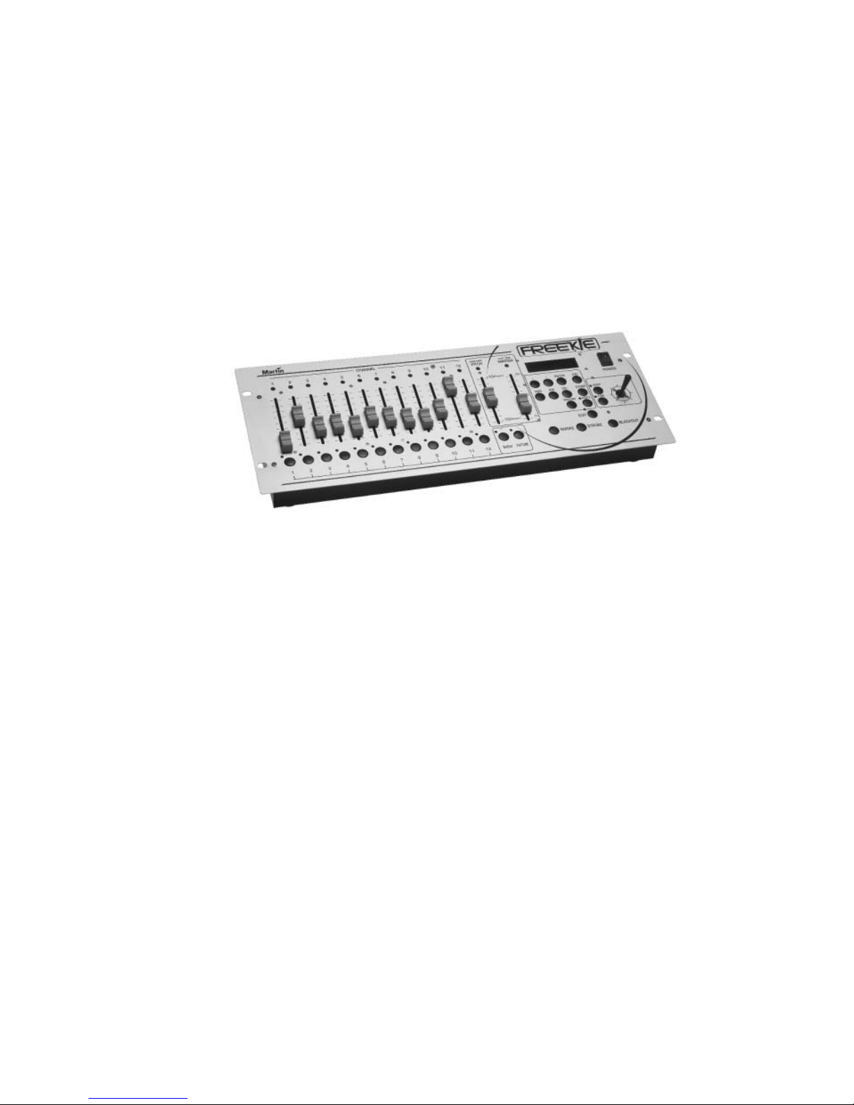
Thank you for selecting the Martin Freekie. This ruggedly built, easy to use
controller offers 12 fixture DMX control and multiple triggering options.
Freekie allows control of up to 12 fixtures (or fixture groups, where each fixture
group comprises similar fixtures that mimic each others’ behavior). Each fixture or
group is controlled with 12 channels. A joystick is provided for easy pan/tilt
adjustment. The Freekie can also cont rol strobe and smoke fixtures. A master fader
allows you to instantly fade all fixtures, and there are multi-purpose buttons which
you can customize to control additional DMX units.
For audio-controlled shows there is the choice of either external signal input or the
Freekie's own internal microphone.
1
FEATURES
• Controls up to 12 fixtures (or fixture groups), each with 12 channels
• 10 banks of 12 programmable shows, each show with up to 10 scenes
• 7-character bank naming
• MIDI triggering of shows
• Follow-spot functionality
• Blackout
• Pitch fader allowing instant speed adjustment during playback of a show
• Joystick for easy pan/tilt control
• Master fader for all fixtures
• Musical triggering of scene changes: Built-in microphone or external control
signal input
• Strobe and smoke fixture control
• Control any DMX512 compatible intelligent light
• Solid steel construction
• Table or 19” rack mount
SAFETY PRECAUTIONS
• The Freekie is not for domestic use.
• Use the device only as described.
• Do not expose the device to rain or moisture.
Introduction
5

• Make sure the device is properly grounded.
• Do not operate the device with the cover removed.
• Immediately repair or replace damaged power cords.
• There are no user-serviceable parts inside; refer all service to a qualified
technician.
6
Introduction

I
NSTALLATION
The Freekie comes with the following:
• 9 volt, 1 amp transformer
• User manual
POWER
2
The device is powered by a 9 volt DC transformer that is supplied with the product.
Connect this to a mains supply and plug it into the DC9V input at the back of the
Freekie.
Note If the plug on the transformer supplied does not match those in
use in your country you may need to purchase an adaptor.
Alternatively, any 9 volt DC transformer with an output of 1 amp
can be used.
CONNECTING THE SERIAL LINK
About serials links
The Freekie sends instructions through a serial data link. The link goes from the
controller’s output to the input of the first lighting fixture and then from the
fixture’s output to the input of the next fixture. It continues output-to-input in a
daisy-chain to all fixtures.
Up to 32 fixtures can be placed on a serial link without amplification.
Adaptor cables may be required when building the data link. There are two
differences to be aware of. First, both 3-pin and 5-pin XLR sockets are common.
(Martin fixtures have 3-pin XLR sockets. On fixtures that have 5-pin XLR sockets,
pins 4 and 5 are not used.)
Installation
7

To build the serial link
1. Use shielded twisted-pair cable. A reliable data connection begins with the right
cable. Microphone cable cannot transmit DMX data reliably over long runs. For best
results, use only cable designed for RS-485 applications. Your Martin dealer has a
range of cables, connectors, and adaptors designed for lig hting control.
2. Starting from the controller, connect output to input. Four parallel DMX outputs, two 3-pin, and two 5-pin are provided on the Freekie.
3. Never use a “Y” connector to split the link. If you need to split the serial link
into branches use a dedicated splitter/amplifier such as the Martin 4-Channel
Opto-Isolated RS-485 Splitter.
4. Don’t overload the link. Placing more than 32 devices on a link can cause
unpredictable performance.
5. Always terminat e the link by installing a ter mination plug in the output socket
of the last fixture on the link. The termination plug, which is a male XLR connector with a 120 ohm resistor soldered between pins 2 and 3, “soaks up” the control signal so it cannot reflect back down the link. If a splitter is used, terminate
each branch of the link.
8
Installation
 Loading...