

Page 1
TM
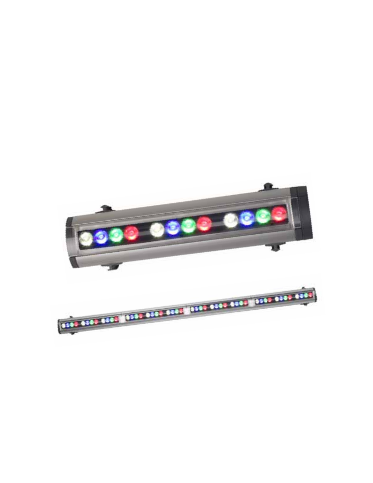
Extube
user manual
Page 2
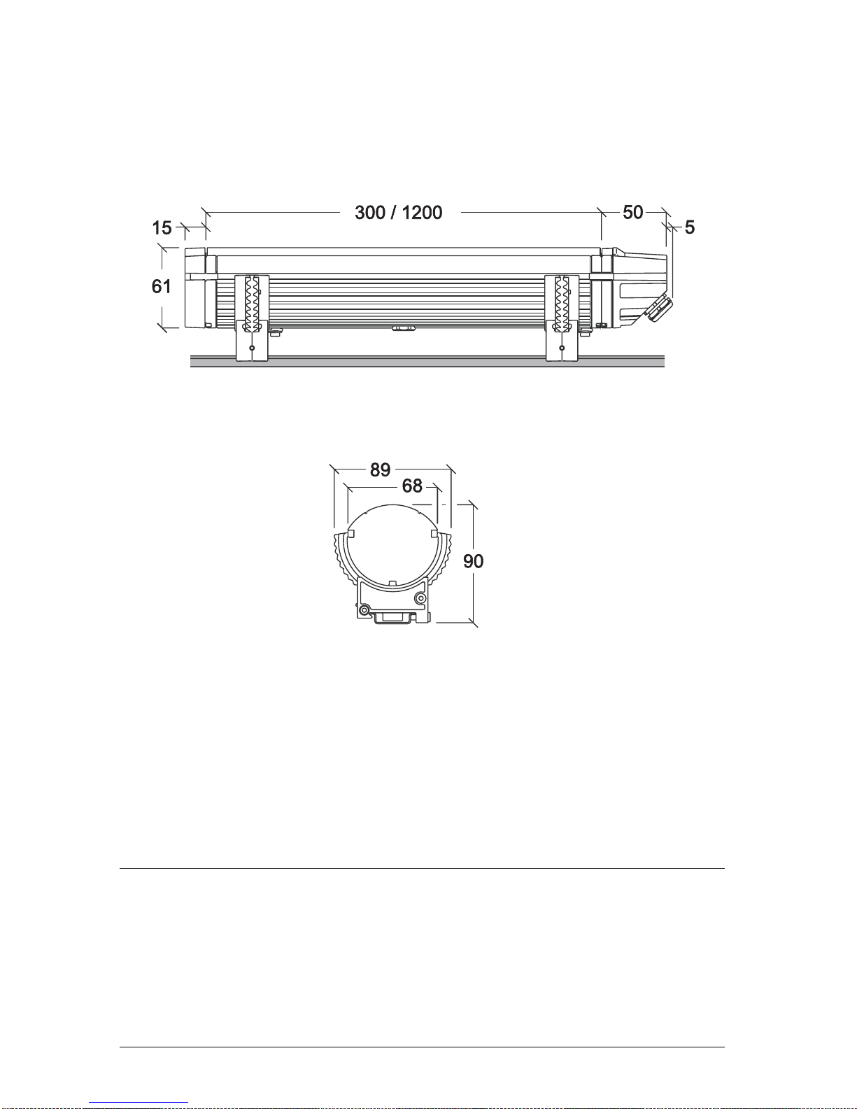
Dimensions
All dimensions are in millimeters
©2008 Martin Professional A/S. Information subject to change without notice. Martin
Professional A/S and all affiliated companies disclaim liability for any injury, damage, direct
or indirect loss, consequential or economic loss or any other loss occasioned by the use of,
inability to use or reliance on the information contained in this manual. The Martin logo, the
Martin name and all other trademarks in this document pertaining to services or products by
Martin Professional A/S or its affiliates and subsidiaries are trademarks owned or licensed
by Martin Professional A/S or its affiliates or subsidiaries.
P/N 35000212, Rev. A
Page 3
Safety Information
Warning! Read the safety precautions in this section before
installing, powering, operating or servicing this product.
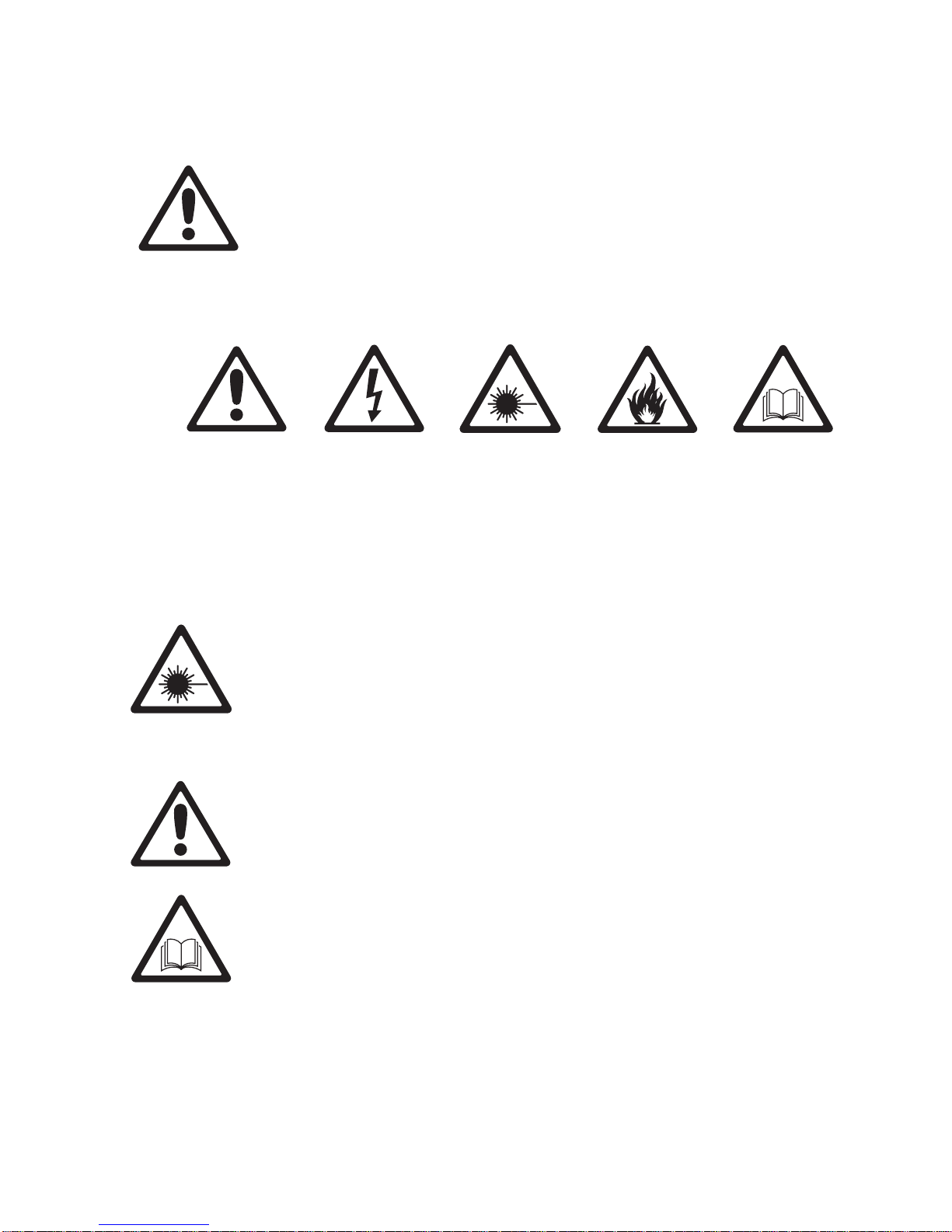
The following symbols are used to identify important safety inf ormation on
the product and in this manual.
DANGER!
Safety hazard.
Risk of severe
injury or death.
Warning! Class 2M LED product. Do not look into the beam from a
distance of less than 40 cm (16 inches). Do not stare into the beam
for extended periods at a short distance. Do not view the beam
directly with optical instruments.
This product is for professional use only. It is not for household use.
This product presents risks of severe injury or death due to fire hazards,
electric shock and falls.
Read this manual before installing, powering or servicing the fixture,
follow the safety precautions listed below and observe all warnings in this
manual and printed on the fixture. Install and operate the fixture only as
described in this manual and in accordance with local laws and
regulations. Refer any operation not described in this manual to a
qualified technician.
Warning!
Hazardous
voltage. Risk of
lethal or severe
electric shock.
Warning!
LED light
emission. Risk
of eye injury.
Warning!
Fire hazard.
Warning!
Refer to user
manual.
If you have questions about how to operate the fixture safely, please
contact your Martin supplier or call the Martin 24-hour service hotline on
+45 8740 0000, or in the USA on 1-888-tech-180.
Safety Information 3
Page 4
PROTECTION FROM ELECTRIC SHOCK
• Shut down power to the entire installation at the power distribution board
and lock out power (by removing a fuse at the distribution board for
example), before removing any input cap, end cap, other cover or part.
Do not reapply power until all caps, retaining clips, cove rs and other
parts have been correctly installed.
• Shut down power to the installation when it is not in use.
• Connect the fixture electrically to ground (earth).
• Use only a source of AC power that complies with local building and
electrical codes and has both overload and ground-fault (earth-fault)
protection.
• Connect the fixture to AC power using an Extube input cap and the 13 A
power cable supplied pre-installed on the input cap only. The power
cable may not be changed by the user. If it is not suitable for your
installation, contact Martin for assistance in selecting and installing an
alternative power cable.
• Terminals inside the input cap are live when power is applied to the
power cable. Do not apply power to the cable unless the input cap is
installed on a fixture as described in this manual.
• Terminals inside the connector at the output end of the fixture are live
when power is applied to the fixture. Do not apply power to the fixture
unless an end cap is installed on the fixture as described in this manual.
• Before using the fixture, check that all power distribution equipment and
cables are in perfect condition, rated for the current requi rements of al l
connected devices, protected to IP67 or higher and of suitable type for
the location (including water, pollution, temperature and UV resistance).
• Isolate the fixture from power immediately if any cap, cable, seal, cover
or other component is damaged, cracked or deformed. Do not reapply
power until repairs have been completed.
• Do not expose any part of the fixture to a high-pressure water jet.
• Do not immerse the fixture in water or any other fluid, or install it in a
location where flooding may occur.
• Refer any service operation not described in this manual to an
authorized Martin Service partner.
4 Extube user manual
Page 5
PROTECTION FROM BURNS AND FIRE
• Do not operate the fixture if the ambient temperature (Ta) exceeds 40°
C (104° F).
• The exterior of the fixture becomes hot, up to 75° C (167° F) during
normal operation. Ensure that accidental physical contact with an
installed fixture is impossible.
• Allow the fixture to cool for 20 minutes before servicing.
• Keep combustible materials (for example fabric, wood, paper) at least
0.5 m (20 in.) away from the fixtu re’s front cover and light output. Keep
flammable materials well away from the fixture.
• Do not modify the fixture in any way not described in this manual or
install other than genuine Martin parts. Do not stick filters, masks or
other materials directly onto LEDs. Use only Martin approved
accessories to mask or modify the light beam.
• Do not attempt to bypass thermostatic switches or fuses. Replace
defective fuses with ones of the specified type and rating only.
• Install the fixture in a well ventilated area only. Provide a minimum
clearance of 10 cm (4 inches) and ensure unrestricted airflow around
the fixture.
PROTECTION FROM INJURY
• The LED emission presents a hazard to eyesight at distances from 4 cm
(1.6 inches) to 40 cm (16 inches) when the eye is exposed to the beam
for longer than 0.25 seconds.
• Do not look at LEDs from a distance of less than 40 cm (16 inches)
without suitable protective eyewear.
• Do not look at LEDs with a magnifying glass or any other optical
instrument that may concentrate the light output.
• Ensure that all external covers, components and installation fittings are
securely fastened.
• Block access below the work area and work from a stable platform
whenever installing, servicing or moving the fixture.
• Ensure that all supporting structures, surfaces, fasteners and lifting
equipment can bear the weight of all the devices they are intended to
support plus an adequate safety margin, and that they conform to local
building and safety regulations.
• Use a sufficient number of fasteners with sufficient corrosion resistance,
dimensions and strength to mount the DIN rail safely. Any nuts used
must be self-locking.
• If the fixture is to be installed in a location where it may cause injury or
damage if it falls, use a secondary means of attachment such as looped
safety wires passing around the fixture.
Safety Information 5
Page 6

Disposing of this product
Martin™ products are supplied in compliance with Directive 2002/96/EC of
the European Parliament and of the Council of the European Union on
WEEE (Waste Electrical and Electronic Equipment), as amended by
Directive 2003/108/EC, where applicable.
Help preserve the environment! Ensure that this product is recycled at the
end of its life. Your supplier can give details of local arrangements for the
disposal of Martin products.
Page 7

Contents
Dimensions . . . . . . . . . . . . . . . . . . . . . . . . . . . . . . . . . . . . . . . . . . .2
Safety Information . . . . . . . . . . . . . . . . . . . . . . . . . . . . . . . . . . . . .3
Introduction . . . . . . . . . . . . . . . . . . . . . . . . . . . . . . . . . . . . . . . . . . .9
Unpacking . . . . . . . . . . . . . . . . . . . . . . . . . . . . . . . . . . . . . . . . .10
Using for the first time . . . . . . . . . . . . . . . . . . . . . . . . . . . . . . . .10
Physical installation . . . . . . . . . . . . . . . . . . . . . . . . . . . . . . . . . . .11
Location and orientation . . . . . . . . . . . . . . . . . . . . . . . . . . . . . . . 11
Mounting the fixture . . . . . . . . . . . . . . . . . . . . . . . . . . . . . . . . . .12
Adjusting tilt angle . . . . . . . . . . . . . . . . . . . . . . . . . . . . . . . . . . .13
Connections – general . . . . . . . . . . . . . . . . . . . . . . . . . . . . . . . . . 15
AC power . . . . . . . . . . . . . . . . . . . . . . . . . . . . . . . . . . . . . . . . . . . .17
Connecting to power . . . . . . . . . . . . . . . . . . . . . . . . . . . . . . . . .18
Control data link . . . . . . . . . . . . . . . . . . . . . . . . . . . . . . . . . . . . . .20
Connecting the data link . . . . . . . . . . . . . . . . . . . . . . . . . . . . . .22
Fixture setup . . . . . . . . . . . . . . . . . . . . . . . . . . . . . . . . . . . . . . . . .23
Setting up a fixture with a PC and MUM . . . . . . . . . . . . . . . . . . 23
Service and maintenance . . . . . . . . . . . . . . . . . . . . . . . . . . . . . . .30
Cleaning . . . . . . . . . . . . . . . . . . . . . . . . . . . . . . . . . . . . . . . . . . .30
Software installation . . . . . . . . . . . . . . . . . . . . . . . . . . . . . . . . . .31
DMX protocols . . . . . . . . . . . . . . . . . . . . . . . . . . . . . . . . . . . . . . . .32
RGB Mode . . . . . . . . . . . . . . . . . . . . . . . . . . . . . . . . . . . . . . . . . 32
RGBW Mode . . . . . . . . . . . . . . . . . . . . . . . . . . . . . . . . . . . . . . .32
HSI Mode . . . . . . . . . . . . . . . . . . . . . . . . . . . . . . . . . . . . . . . . . .33
HSIC Mode . . . . . . . . . . . . . . . . . . . . . . . . . . . . . . . . . . . . . . . .33
Troubleshooting . . . . . . . . . . . . . . . . . . . . . . . . . . . . . . . . . . . . . .34
Specifications . . . . . . . . . . . . . . . . . . . . . . . . . . . . . . . . . . . . . . . .35
Page 8

8 Extube user manual
Page 9

Introduction
Thank you for selecting an Extube™, a compact LED-based
color-changing lighting fixture from Martin™. The Extube is available in
short 300 mm (11.8 inch) and long 1200 mm (47.2 inch) models. All
models can be plugged into each other end-to-end to form an unbroken
line of light. Each 300 mm fixture or 300 mm segment of a 1200 mm
fixture can be considered as one pixel that can be controlled separately
via DMX, or fixtures and segments can be controlled together as a group.
Diffuser filters that give wider beam angles are available.
This product features:
• Philips Rebel high-power LEDs
• RGBW (red, green, blue, white) color mixing, with RGB, RGBW, HSIC
(hue, saturation, intensity, color temperature) and HSI color control
options
• 100 W LED power and 1392 lumens total output (at very narrow beam
angle) from 1200 mm models
• 25 W LED power and 348 lumens total output (at very narrow beam
angle) from 300 mm models
• Four models available: one Very Narrow beam angle model with no
diffuser fitted, and Narrow, Medium and Wide beam angles with
corresponding diffuser filters installed
• DMX 512A control
• Remote configuration over the DMX data link using a PC with Martin
MUM software and a hardware interface (Martin DABS1 recommended)
• Cascading auto-addressing (automatic DMX address setting of fixtures
connected to the master fixture)
• Auto-sensing power supply unit with 100 - 120/200 - 240 V, 50/60 Hz
operating range
• Clamp mounting system on standard
• Rapid end-to-end connection system
For the latest firmware updates, documentation, and other information
about this and all Martin Professional products, please visit the Martin
website at http: //w w w.martin.com
Introduction 9
Page 10

Comments or suggestions regarding this user manual may be e-mailed to
service@martin.dk or posted to:
Service Department
Martin Professional A/S
Olof Palmes Allé 18
DK-8200 Aarhus N
Denmark
Unpacking
The following items are included with the Extube:
• Adjustable mounting bracket
• This user manual
Using for the first time
Before applying power to the fixture:
• Carefully review “Saf ety Information” on page 3.
• Check that the local AC power voltage is within the range listed on the
fixture’s serial number label.
• Install the fixture as described in this manual
10 Extube user manual
Page 11
Physical installation
Warning! Read "Safety Information" on page 3 before installing the
Extube.
Warning! The safety and suitability of lifting equipment, installation
location, anchoring method, mounting har dware and electrical
installation is the responsibility of the installer. All local safety
regulations and legal requirements must be observed when
installing and connecting the Extube. Installation must be carried
out by qualified professionals only.
Contact your Martin supplier for assistance if you have any
questions about how to install this product safely.
Location and orientation
Warning! The Extube must be clamped onto a a DIN top-hat rail that
is securely anchored to a suitable flat surface. Ensure that the
supporting structure can bear the weight of all installed devices plus
an adequate safety margin.
Warning! If no diffuser filter is installed, make sure that it is
impossible for LEDs to be viewed from a distance of less than 40 cm
(16 inches).
If the diffuser front is installed, there is no eye hazard at any distance.
important! Make sure that there will be at least 10 cm (4 inches) of
free space and unrestricted airflow around the Extube.
The Extube can be installed outdoors. It has an IP rating of 65 and is
designed to withstand rain and other low-pressure water projections, but:
• Do not expose it to high-pressure water jets from any direction.
• Do not immerse it in water or any other fluid.
• Do not install it in a location where flooding may occur.
If installing in an enclosed area, make sure that water can drain awa y from
the installation area at lea st as fast as it can enter it.
The Extube requires free and unobstructed airflow around it to ensure
adequate cooling:
• Do not cover the fixture or locate it in an unventilated space.
• Allow 10 cm (4 inches) free space around the fixture.
Physical installation 11
Page 12
• Keep combustible materials (for example fabric, wood, paper) at least
2.5
0.5 m (20 in.) away from the fixture’s front cover and light output. Keep
flammable materials well away from the fixture.
The housing can reach temperatures up to 75° C (167° F). Restrict public
access or locate the fixture so that it cannot accidentally be touched.
Mounting the fixture
Warning! The Extube must be mounted on a top-hat profile 35 mm
(1.4 inch) DIN rail that is securely anchored to a surface. The
installation must conform to local electrical, building, safety and fire
regulations. If there is a danger that fixtures may cause injury or
damage if they fall, use a means of secondary attachment such as
safety cables looped around the fixtures.
Corrosion-resistant DIN rail can be ordered from Martin (see
"Accessories" on page 37).
To mount the Extube on
a surface using 35 mm
DIN rail:
1. Fasten the DIN rail
securely to the
mounting surface.
A
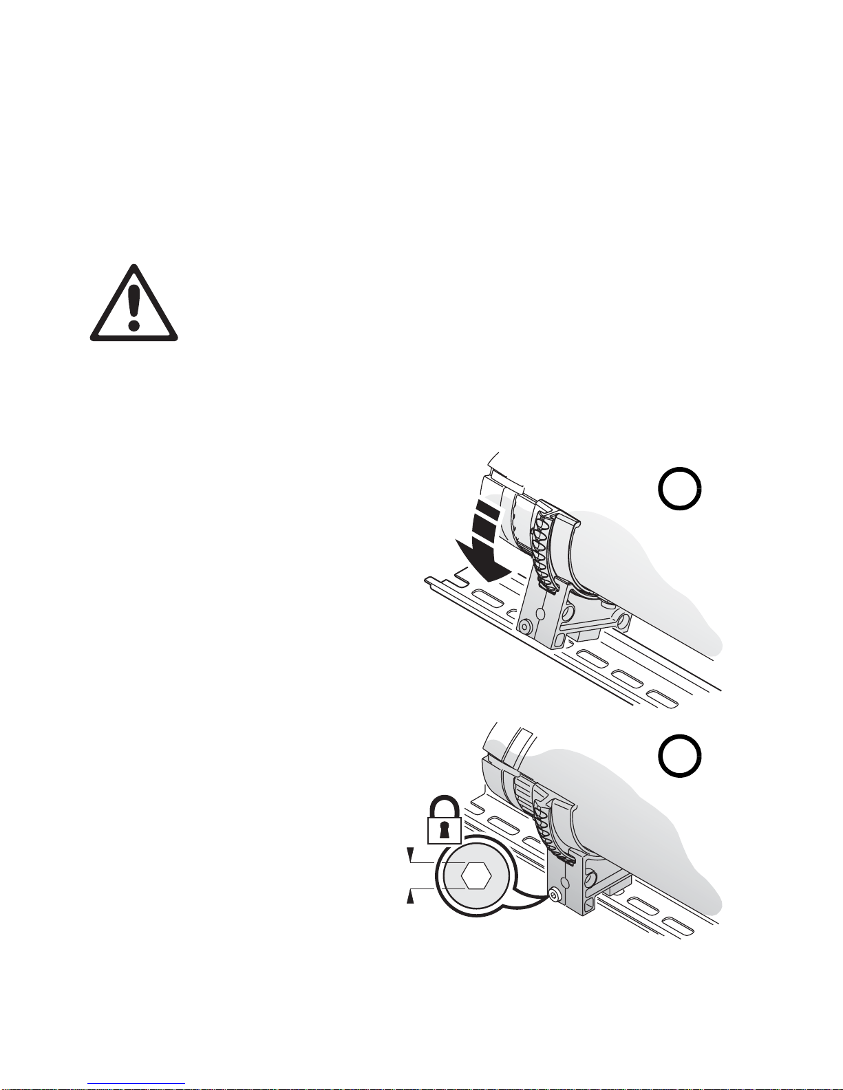
2. See Figure 1. The
Extube mounting
bracket has a
hooked profile on
one side. Hook this
profile over the top
of the DIN rail and
swing the bracket
down (see A). Use a
2.5 mm Allen ke y to
tighten the mounting
clamp screw (see
B).
B
2.5
Figure 1: Mounting on DIN rail
12 Extube user manual
Page 13

Adjusting tilt angle
The Extube can be tilted through 90° (see Figure 2).
To adjust the tilt angle:
1. See Figure 3. Insert a 4 mm Allen key in the holes next to the
mounting clamp screws on the mounting brackets of all interconnected
fixtures. Engage the Allen key in the screw inside each hole, apply a
little inwards pressure and twist a quarter-turn clockwise to release the
tilt lock.
Figure 2: Tilt range
2. Adjust the fixture(s) to the desired tilt angle.
3. Re-insert the Allen key and twist a quarter-turn counter-clockwise to
reapply the tilt lock.
Figure 3: Releasing the tilt lock
Physical installation 13
Page 14

4. Check that the tilt lock is applied
on all the mounting brackets.
See Figure 4. A small button on
the opposite side of the
mounting bracket to the tilt lock
screw indicates whether the tilt
lock is applied or not.
Figure 4: Tilt lock indicato r
14 Extube user manual
Page 15

Connections – general
See Figure 5. The Extube must be connected to power and control data
by plugging an Extube input cap into the input en d of the fixture.
Input cap End cap
DMX control data in
Power in
Figure 5: Connecting fixtures to data and power
A second Extube can be plugged into the output end of this fixture, a third
Extube can be plugged into the output end of the second fixture, and so
on until the connected fixtures reach the maximum permitted length (see
"Maximum interconnected length per power input" on page 36).
Warning! Do not exceed the maximum length specified for a line of
Extube fixtures connected to each other and supplied with power via
one input cap, or you will overload the power cable and other
components and create a serious safety risk.
If another Extube is not plugged into the output end of a fixture, an end
cap must be installed as shown in Figure 5.
Input and end caps are supplied in Extube Connection Kits that must be
ordered separately. Each kit contains one input cap with 1.8 m (71 in.)
power and data cable tails, plus one end cap. Kits are available with
standard EU wire colors for EU markets and with standard US wire colors
for US markets (see "Accessories" on page 37 for deta i l s).
Connections – general 15
Page 16

When installing
input and end
caps, use the clips
provided with the
caps to secure
them to the fixture.
Clips are installed
by pressing them
into the slots
provided in fixtures
and end caps (see
Figure 6). Clips
can be released b y
levering them
outwards at one
end with a small
flat-blade
screwdriver.
Figure 6: Input and end cap clips
Warning! Do not apply power to an installation unless all input caps
and end caps are installed and secured with two clips per cap.
See Figure 7. It is possible to create a gap in a line of Extube fixtures (to
pass a door, window or corner, for example) but keep the fixtures
connected to each other by using an Extube Extension Kit that is available
as an accessory. Fixtures connected to each other using an extension kit
can be controlled together as a group.
Extension
End capInput cap End cap
InputOutput
Figure 7: Extension kit
Extension kits are available with 250 mm (9.8 in.) or 2 m (78 in.) cable
lengths in EU versions for EU markets and US versions for US markets
(see "Accessories" on page 37 for details).
16 Extube user manual
Page 17

AC power
Warning! Read “Safety Information” on page 3 before attempting to
install this product. Lock out power to the entire installation before
working on cables an d connections or removing any cover.
Electrical installation must be carried out by qualified professionals
only.
For protection from dangerous electric shock, the fixture must be
grounded (earthed). The AC mains power distribution system must
be fitted with both current overload and ground-fault (earth-fault)
circuit breakers, as well as a means to isolate fixtures from power
and lock out power during service.
Important! Do not connect the Extube to an electrical dimmer
system. Doing so can damage the electronics.
If you require help in planning or dimensioning the power distribution
system, please contact your Martin supplier for assistance.
If there is a break or cut at any point in a cable (for example at a
connection point), and if this is exposed to water, moisture can be drawn
up the inside of the cable due to the vacuum effect of temperature
fluctuations during operation. Ensure that the fixture is protected from the
entry of water via the power cable by using IP65-rated connectors or
junction boxes, or by protecting connectors with weatherproof housings.
The Extube does not have a power on/off switch. Power is applied to the
fixture as soon as it is connected to power.
AC mains power voltage and frequency
The Extube accepts AC power at 100 - 120 and 200 - 240 V nominal, at
50 or 60 Hz. Do not connect the fixture to power at any other voltage or
frequency.
Current and fuse ratings
See "Typical Power and Current" on page 36 for details of current drawn
by Extube fixtures.
Extube 300 mm fixtures are protected by a 1 amp slow-blow primary fuse
and 1200 mm fixtures are protected by four 1 amp slow-blow fuses. Fuses
are located internally on the power PCB and are not user-serviceable. If
you suspect that a fuse has blown, please contact your Martin supplier for
assistance.
AC power 17
Page 18

Connecting to power
An Extube fixture or group of fixtures must be supplied with power via the
13 A power cable installed on an Extube power input cap.
Details of standard US and EU conductor identification systems are given
in Table 1.
Wire color
(US system)
black brown live L yellow or
white blue neutral N silver
green yellow/green ground
Warning! Terminals inside the input cap are live when power is
applied to the power cable. Terminals inside the connector at the
output end of the fixture are live when power is applied to the fixture.
Do not apply power to the power cable unless the input cap is
installed on the fixture and an end cap is installed either on the
fixture or on the last fixture in a line of interconnected fixtures.
To connect to power:
Wire color
(EU system) Conductor Symbol Screw (US)
brass
green
(earth)
Table 1: Conductor identification
1. Lock out power to the installation.
2. Install an end cap on the fixture or on the last fixture in a line of
fixtures.
3. Connect the power cable on the input cap to the power distribution
circuit as follows:
- Connect the green wire (US models) or yellow/green wire (EU
models) to ground (earth)
- Connect the white wire (US models) or blue wire (EU models) to
neutral
- Connect the black wire (US models) or brown wire (EU models) to
live.
4. Install the input cap on the fixture you want to supply with power , check
that all installation work is completed and carry out appropriate tests
and safety checks before applying power to the installation.
18 Extube user manual
Page 19

Power plug
If you decide to fit the supplied power cable with a plug that is suitable for
your AC mains power outlets, install a grounding-type (earthed) pl ug that
is rated 13 A minimum, following the plug manufacturer’s instructions.
Table 1 shows some possible pin identification schemes; if pins are not
clearly identified, or if you have any dou bts about proper installation,
consult a qualified electrician. Ensure that all connections are sufficiently
protected from water.
AC power 19
Page 20

Control data link
Extube fixtures must be connected via a data link to allow DMX control.
The following considerations must be taken into account when planning
the data link:
• RS-485 data cable designed for exterior use is required for outdoor
installations. RS-485 cable has low capacitance and a characteristic
impedance of 85 to 150 Ohms. It is electrically shielded and has at least
1 twisted pair of conductors. The minimum recommended wire size is
0.25 mm
(22 AWG) for run s up 500 meters (1640 ft). CAT 5e network cable
designed for direct burial can be used in outdoor installations, but you
are recommended to run it inside conduit.
• CAT 5e network cable is suitable for the control data link in indoor
installations. Installation-type cable is acceptable for fixed installations.
Flexible patch-type cable with good bend and torsion recove ry is
required in movable installations (Martin patch cables are
recommended).
• Long parallel runs of AC power and control data cables may cause
interference on the data link and must be avoided. Even if not required
by law, use separate conduits for power and data cables.
2
(24 AWG) for runs up to 300 meters (1000 ft.) and 0.32 mm2
• The maximum permitted control data cable length before a control
signal amplifier is required is 500 meters (1640 ft.). An optically isolated
amplifier-splitter such as the Martin RS-485 Opto-Splitter (P/N
90758060) must be used to extend a link beyond this length.
• If you want to control more than one single line of interconnected
Extubes, yo u must either use one DMX output from your controller for
each line of fixtures or use an optically isolated amplifier-splitter such as
the Martin RS-485 Opto-Splitter to split the data link into one branch for
each line of Extubes. The Martin Opto-Splitter all ows you to split a link
into four branches.
• Each link or branch of a link must be terminated by installing an end cap
on the last fixture.
• One DMX universe has 512 DMX control channels availabl e. If
individual control of the fixtures in an installation is required, each fixture
must be given its own channels until the limit of 512 is reached. At this
point, a new DMX universe must be created.
• The number of fixtures that can be individually controlled in one DMX
universe depends on the number of DMX channels they use. if Extubes
are set to HSI mode, for example, each fixture requires 3 DMX
channels. The total number of Extubes that can be linked in one DMX
universe will therefore be 512/3 = 170.
20 Extube user manual
Page 21

When planning DMX cable layout, remember that the maximum
current-carrying capacity of cables and fixtures limits the length of the line
of fixtures that can be connected via one input cap (see "Installation" on
page 36).
Data connection pinouts
XLR connection
XLR connectors are suitable if the DMX controller has XLR output
sockets. DMX cable is recommended for the data link in this case. XLR
pin numbers are normally marked on connectors. Connectors must be
wired using the standard XLR DMX pin-out:
• Pin 1: Cable shield
• Pin 2: DMX Data 1 - (cold)
• Pin 3: DMX Data 1 + (hot)
To avoid ground/earth loop interference, ensure that the DMX cable shield
does not come into contact with the shell or body of XLR connectors.
RJ-45 connection
RJ-45 connectors are suitable if the DMX controller has RJ-45 output
sockets. CAT 5e network cable is recommended in this case. RJ-45 cable
connector pins are numbered from the left looking at the face of the
connector with the locking clip on top (see Figure 8). Connectors must be
wired according to the 568-B system using the standard RJ-45 pin-out for
DMX applications:
• Pin 1 (White/orange): DMX data hot (+)
• Pin 2 (Orange): DMX data cold (-)
• Pins 7 (White/brown) and 8
(Brown): Common
Pins 3 and 6 are available for Data 2
connections in DMX 512-A or
similar systems. They must be
Pin 1 Pin 8
wired as follows:
• Pin 3 (White/green): Available for
Data 2 hot (+)
Figure 8: RJ-45 cable
connector pins
• Pin 6 (Green): Available for Data
2 cold (-)
Pins 4 and 5 are not used in currently available lighting control systems
but can be wired as follows:
• Pin 4 (Blue)
• Pin 5 (White/blue)
Control data link 21
Page 22

Connecting the data link
Warning! Lock out power to the entire installation before working on
cables and connections or removing any cover.
Warning! Make sure that data connections are totally protected from
water , or moisture may be dra wn up the inside of the cable due to the
vacuum effect from the heat generated during operation.
The Extube is supplied with a 1.8 meter (5 ft.10 in.) data cable tail for data
connection. The cable contains both input and output conductors that are
identified as follows:
• 1 x shield = data input and output common
• 2 x white wires = data input and output hot (+)
• 1 x green wire = data input cold (-)
• 1 x brown wire = data output cold (-)
To connect a fixture to the data link:
1. Connect the conductors in the fixture’s cable tail to the data link
respecting the above color code. If required, install input and output
connectors on the data cable respecting the pinouts described in “Data
connection pinouts” on page 21. Standard procedure is to use a male
connector on a fixture’s cab le tail for data input and a female connector
for data output. Do not connect the shield conductor to ground (earth)
or allow it to come into contact with a connector shell, as this may
cause interference.
2. Protect connectors in a weatherproof housing if they are not totally
weatherproof.
22 Extube user manual
Page 23

Fixture setup
Setting up a fixture with a PC and MUM
The Martin MUM (Multi-Utility Manager) application allows you to program
and configure Martin lighting products from a laptop and features an
intuitive GUI (graphic user interface). Refer to the MUM user manual for
instructions on installing and starting the MUM application.
Using MUM, you can connect to and set up one Extube fixture or one
interconnected line of fixtures at a time.
To connect a PC with MUM to an Extube:
1. Obtain the MUM application, a DABS1 adaptor and interface cables.
These are available as a set from Martin, P/N 90758090.
2. Connect the DABS1 adaptor to y our PC using the USB cable supplied
in the set.
3. Connect the DABS1 adaptor to the Extube or line of Extubes using an
XLR connector connected to the Extube data input cable.
4. Apply power to the Extube and start the MUM application. MUM will
automatically detect an Extube if it is powered on and correctly
connected. It will also retrieve information and current settings from
the fixture and display them.
Communication between MUM and fixtures
When there is a connection to a fixture:
• The Reconnect button at the bottom of every window in MUM lets you
re-initialize communicat ion with the f ixture or establish communication if
you connect to a new Extube.
• The Refresh button retrieves and displays fresh fixture information.
• The Close button closes the MUM application.
Fixture setup 23
Page 24

Communicating with segments
A segment consists of either a single 300 mm Extube or a 300 mm section
of a 1200 mm Extube. Depending on how you set up the installation,
segments can be controlled separately or put into groups.
If you are connected to a line of two or more interconnected fixtures, MUM
lets you select which segment to communicate with and gives you
information about segments. In the example below:
a. MUM is communicating with segment 1.
b. The installation ranges from 1 to 14 segments, i.e. there are 14
segments in total.
c. Use the arrows to scroll between segments.
a
b
C
24 Extube user manual
Page 25

Fixture information
The Fixture info window identifies the fixture and software version
installed.
The Fixture info window also displays information about the number of
hours the fixture has been powered on and the number of hours LEDs
have been active. In both cases, one non-resettable counter shows the
total number of hours since manufacture and one resettable counter
shows the number of hours since it was lest reset.
The Extube’s software monitors operation. If it detects an error , it displa ys
diagnostic information in the Fixture info window.
The segment information above the Reconnect button tells you which
segment MUM is retrieving fixture information from. You can use the
segment selection arrows to scroll between segments and retrieve
information from all the segments you have connected to.
Fixture setup 25
Page 26

Fixture settings
The Fixture settings window lets you select DMX modes (i.e. color
control options), group segments into pixels, and set DMX addresses.
DMX mode
The Fixture settings window lets you select a DMX mode (RGB, RGBW,
HSI or HSIC color control) for the fixtures or pixels in your installation. It is
possible to set different pixels to different DMX modes by scrolling
between pixels using the scroll arrows and changing the DMX mode
setting for each pixel.
Individual and grouped control of segments
The Fixture settings window lets you control 300 mm Extubes or 300 mm
segments of 1200 mm Extubes individually, or put them into groups that
behave identically and are controlled as one pixel.
For example, if you select 1 in the Segments/Pixel box, each 300 mm
segment in the line of fixtures is controlled individually as one pixel that is
300 mm long.
If you select 3 in the Segments/Pixel box, the 300 mm segments are put
into groups of three segments. You then control each group as one pixel
that is 900 mm long.
Note that you cannot set different segments within one pixel to different
DMX modes.
26 Extube user manual
Page 27

DMX address setting – general
The DMX address, also known as the start channel, is the first of the DMX
channels used to receive instructions from the controller. For individual
control, each pixel must have its own channels. Thus, if a pixel has DMX
address 1 and uses 3 channels because it is set to RGB mode, it will use
channels 1 - 3. The DMX address of the next pixel must be set to 4, and
so on.
The Extube features ‘cascading’ auto-addressing. This means that once
you have connected MUM to the first Extube in an interconnected line and
set that first fixture’s DMX address, you can automatically set the DMX
addresses of all the pixels in that line.
DMX address setting in single lines of Extubes
If you intend to use a DMX controller to operate one Extube or one line of
interconnected Extubes only, and you want all the segments to behave
identically, leave DMX address set to 1, enter the total number of
segments in your installation in the Segments/Pixel box, select Enable
auto configure all segments, and click on Auto co nfigure now. You can
now control one pixel containing all the segments in your installation. You
will use DMX channels 1 - 3 or 1 - 4 (depending on the DMX mode you
have selected) on your controller to control all the segments together.
If you intend to use a DMX controller to operate one line of interconnected
Extubes only but you want individual control of pixels , leav e DMX address
set to 1, enter 1 in the Segments/Pixel box, select Enable auto
configure all segments, and click on Auto configure now. You can no w
control all the segments in your installation separately as individual pixels .
You will use 3 or 4 (depending on the DMX mode you have selected) DMX
channels per segment, starting at channel 1 on your control l e r.
DMX address setting in multiple lines of Extubes and in mixed
installations
If you intend to use one DMX controller to control more than one line of
interconnected Extubes – or to control a mixed installation containing
Extubes and other fixtures – you will need to set the DMX addresses on
all fixtures for which individual control is required.
If you set the DMX address of the first segment you are connected to,
select Enable auto configure all segments and then click on Auto
configure now, the first Extube you are connected to automatically
calculates and sets the DMX addresses of all the segments connected to
it starting with the first segment’s DMX address and then adding
addresses in ascending order.
For example , if your installation consists of 10 interconnected segments
set to two segments per pixel (giving you five segments), with all
segments in RGBW mode (so that they use 4 DMX channels), and the
Fixture setup 27
Page 28

first segment has DMX address 101, auto configuring will set the DMX
address of the first pixel to 101, the next pixel to 105, the next pixel to 109,
and so on until the last pixel is set to DMX address 117. The last pixel will
use channels 117 to 120 and channel 121 will be available for other
fixtures.
Monitoring fixture parameters
PCB voltage data and LED and PCB temperatures for each segment
MUM communicates with can be displayed in MUM’s Monitor window.
28 Extube user manual
Page 29

LED Test
The Extube’s LEDs can be activated with out a DMX controller for test
purposes in MUM’s LED Test window.
Auto test all starts colors fl ashing in sequence. Flash speed can be
adjusted.
Fixture setup 29
Page 30

Service and maintenance
Warning! Read “Safety Information” on page 3 before carrying out
serv ice or m ain tenan ce wor k on the Ext ube. Lock out power to the
entire distribution system before servicing or opening any
cover.
Important! Excessive dirt and dust buildup degrades performance,
causes overheating and will damage the fixture. The Extube requires
cleaning at intervals that depend on the environment in which it is
installed. Damage caused by inadequate cleaning is not covered by
the product warranty.
The Extube, its power input cap with installed cable, and its end cap are
not user-serviceable. All service apart from cleaning, software renewal
and the installation work described in this manual must be carried out by
the Martin Service organization or its authorized agents.
It is Martin policy to use the best quality materials available to ensure
optimum performance and the longest possible component lifetimes.
Howev er , optical components in all lighting fixtures are subject to wear and
tear over the life of the fixture, resulting in gradual changes in color
rendition, for example. The extent of wear and tear depends heavily on
operating conditions and environment, so it is impossible to specify
precise lifetimes for optical components. LEDs will eventually require
replacement if their characteristics are affected by wear and tear after an
extended period of use and if you require fixtures to perform within very
precise optical and color parameters. The expected lifetime (to 50% of
initial output level) of the Extube’s LEDs is minimum 20 000 hours at full
intensity.
Cleaning
Regular cleaning is essential for fixture life and performance. Buildup of
dust and dirt degrades the fixture’s light output and cooling ability.
Cleaning schedules will vary greatly depending on the operating
environment. It is therefore impossible to specify precise cleaning intervals
for the Extube. Inspect fixtures within their first few weeks of operation to
see whether cleaning is necessary. Chec k again at frequent intervals. This
procedure will allow you to assess cleaning requirements in your particular
situation. If in doubt, consult your Martin dealer about a suitable
maintenance schedule.
30 Extube user manual
Page 31

Warning! The Extube is IP65 rated. This means that it will withstand
water projections, but do not e xpose it to high-pressure water jets or
immerse it in water or any other liquid.
Clean the Extube’s housing and front glass with a soft cloth dampened
with a solution of water and a mild detergent such as car shampoo. Take
care not to damage seals and wiring during cleaning. Do not use products
that contain solvents, abrasiv es or caustic agents for cleaning, as they can
cause surface damage to the fixture and its front cover.
Software installation
It may be necessary to upload new software (i.e. firmware) to the Extube if
you believe that the product has a software-related fault or if you wan t to
update to a newer version. Software updates are availab le from the Martin
website (http://www.martin.com) and can be installed via the DMX data
link with the following items:
• The Martin Uploader application, version 5.0 or later , downloadable free
of charge from the Support area of the Martin website.
• The Extube main CPU software update file, downloadable free of
charge from the Support area of the Martin website (this file can be
downloaded automatically from within the Ma rtin Uploader application)
• A Martin Universal USB-DMX Interface or similar PC/fixture hardware
interface and a Windows PC (if you have a Martin MP-2 Uploader
device, it can also be used).
To install new software:
1. Connect the uploader hardware to an Extube fixture’s data input
connector. The software will be uploaded to that fixture and all Extube
fixtures that are powered on and connected via the DMX link.
2. Upload the fixture software as described in the uploader’s help file or
user documentation.
3. Disconnect the uploader hardware and reconnect the fixture to the
DMX link.
4. Cycle power off and on. Check that the fixture operates correctly. If it
does not, cycle power off and on again and check that the fixture now
operates correctly. If it still does not, repeat the upload procedure.
Service and maintenance 31
Page 32

DMX protocols
RGB Mode
Start code = 0
Channel Value Percent Function
1
2
3
RGBW Mode
Channel Value Percent Function
1
2
0 - 255 0 - 100%
0 - 255 0 - 100%
0 - 255 0 - 100%
Start code = 0
0 - 255 0 - 100%
0 - 255 0 - 100%
Red
Intensity 0
Green
Intensity 0 →100%
Blue
Intensity 0 →100%
Red
Intensity 0
Green
Intensity 0 →100%
→100%
→100%
3
4
32 Extube user manual
0 - 255 0 - 100%
0 - 255 0 - 100%
Blue
Intensity 0
White
Intensity 0
→100%
→100%
Page 33

HSI Mode
Channel Value Percent Function
Start code = 0
Hue
1
0 - 255 0 - 100
Red
→ Orange → Amber→
Yellow
Blue
Magenta → Red
→ Green → Cyan →
→ Indigo → Violet →
2
3
In HSI mode, white color temperature is fixed at 5500 K.
HSIC Mode
Channel Value Percent Function
1
0 - 255 0 - 100
0 - 255 0 - 100%
Start code = 0
0 - 255 0 - 100
Saturation
Zero (white)
Intensity
Intensity 0
Hue
Red → Orange → Amber→
Yellow
Blue
→ Indigo → Violet →
Magenta → Red
→ Full
→100%
→ Green → Cyan →
2
3
4
In HSIC mode, a DMX value of 191 (75%) must be sent on channel 4 to
obtain a white color temperature of 5500 K.
Saturation
0 - 255 0 - 100
0 - 255 0 - 100%
0 - 255 0 - 100
DMX protocols 33
Zero (white)
Intensity
Intensity 0
Color Temperature Control
2000 - 10 000 K
→ Full saturation
→100%
Page 34

Troubleshooting
Problem Probable cause(s) Remedy
Fixture is completely
dead.
One or more fixtures
responds incorrectly
to control or does not
respond at all.
LEDs cut out
intermittently.
No power to fixture. Check power and connections.
Primary fuse blown.
Fault on DMX link.
Incorrect fixture addressing.
Fixture defective.
Other device on DMX link
defective.
Fixture is too hot.
Isolate fixture from power. Contact
Martin for service.
Inspect connections and cables.
Correct poor connections. Repair
or replace damaged cables.
Check fixture is set to correct DMX
mode.
Check number of channels
required by fixture’s DMX mode
and check fixture addresses.
Have faulty fixture serviced by
Martin service technician.
Bypass devices on DMX link until
the faulty device has been
identified.
Have faulty device tested and
serviced by Martin service
technician or device supplier.
Ensure free airflow around fixture.
Clean fixture.
Check that ambient temperature
does not exceed maximum
permitted level.
Contact Martin for service.
Table 2: Troubleshooting
34 Extube user manual
Page 35

Specifications
Physical
Length. . . . . . . . . . . . . . . . . . . . . . . . . .300 mm (11.8 in.) / 1200 mm (47.2 in.),
. . . . add 70 mm (2.8 in.) if end cap and power input module installed
Width. . . . . . . . . . . . . . . . . . . . . . . . 89 mm (3.5 in.) including mounting bracket
Height . . . . . . . . . . . . . 90 mm (3.5 in.) including mounting bracket and DIN rail
Weight. . . . . . . . . . . . . . . . . . . . . . . . . . . . . . . .300 mm model: 750 g (26.5 oz.)
. . . . . . . . . . . . . . . . . . . . . . . . . . . . . . 1200 mm model: 3 kg (6.6 lbs.)
Dynamic Effects
Color mixing . . . . . . . . . . . . . . . . . . . . . . . . . . . . . . . . . . . . . . . . . . . . . . RGBW
Red. . . . . . . . . . . . . . . . . . . . . . . . . . . . . . . . . . . . . . . . . . . . . . . . . . . .0 - 100%
Green . . . . . . . . . . . . . . . . . . . . . . . . . . . . . . . . . . . . . . . . . . . . . . . . . .0 - 100%
Blue. . . . . . . . . . . . . . . . . . . . . . . . . . . . . . . . . . . . . . . . . . . . . . . . . . . .0 - 100%
White. . . . . . . . . . . . . . . . . . . . . . . . . . . . . . . . . . . . . . . . . . . . . . . . . . .0 - 100%
Control and Programming
Color control modes . . . . . . . . . . . . . . . . . . . . . . . . . . RGB, RGBW, HSI, HSIC
Control . . . . . . . . . . . . . . . . . . . . . . . . . . . . . . . . . . . . . . . . . . . . . . . . . . . . DMX
DMX channels . . . . . . . . . . . . . . . . . . . . . . . . . . . . . . . . . . . . . . . . . . . . . . . 3/4
Grouped pixel control options. . . . 1 x 3 (all as one group) on 300 mm models,
. . . . . . . . . . . . 1 x 12 (all as one group) or 4 x 3 on 1200 mm models
DMX address setting . . . . . . . . . . .Auto-addressing and Martin MUM software
26-bit control (internal) . . . . . . . . . . . . . . RGBW, RGB, HSI, HSIC color mixing
Protocol. . . . . . . . . . . . . . . . . . . . . . . . . . . . . . . . . . . . . . . . . .USITT DMX512-A
Receiver . . . . . . . . . . . . . . . . . . . . . . . . . . . . . . . . . . . . . . . . . . . . . . . . . RS-485
Firmware update. . . . . . . . . . . . . . . . . . . . . . . . . . . . Serial upload via DMX link
Photometric Data
Light source . . . . . . . . . . . . . . . . . . . . . . . . .Luxeon Rebel high power emitters
Total LED power . . . . . . . . . . . . . . . . . . . . . . 25 W approx. on 300 mm models,
Color temperature control. . . . . . . . . . . . . . . . . . . . . . . . . . . . .2 000 - 10 000 K
Total output per 300 mm segment (balanced white, 5600 K)
Very narrow (19° half-peak) . . . . . . . . . . . . . . . . . . . . . . . . . . . . . . . . . . .348 lm
Narrow (27° half-peak) . . . . . . . . . . . . . . . . . . . . . . . . . . . . . . . . . . . . . . .324 lm
Medium (34° half-peak) . . . . . . . . . . . . . . . . . . . . . . . . . . . . . . . . . . . . . .301 lm
Wide (40° half-peak). . . . . . . . . . . . . . . . . . . . . . . . . . . . . . . . . . . . . . . . .259 lm
For full photometric data please see www.martin.com
. . . . . . . . . . . . . . .100 W approx. on 1200 mm models
Specifications 35
Page 36

Construction
Housing . . . . . . . . . . . . . . . . . . . . . . . . . . . . . . . . . . . . . . . . . . . . . . . Aluminum
Finish . . . . . . . . . . . . . . . . . . . . . . . . . . . . . . . . . Clear anodized, black or white
End covers . . . . . . . . . . . . . . . . . . . . . . . . . . . UV-resistant clear polycarbonate
Mounting brackets . . . . . . . . . . . . . . . . . . . . . . . . . . . . . . . . . . . . . . . PA6 nylon
Protection rating . . . . . . . . . . . . . . . . . . . . . . . . . . . . . . . . . . . . . . . . . . . . . IP 65
Installation
Orientation . . . . . . . . . . . . . . . . . . . . . . . . . . . . . . . . . . . . . . . . . . . . . . . . . . Any
Vertical aiming . . . . . . . . . . . . . . . . . . . . . . . . . . . . . . . . . . . . . . . . . . . . .+/- 90°
Mounting points . . . . . . . . . . . . . . . . . . . . Mounting brackets or 35 mm DIN rail
Maximum interconnected length per power input
100 V, 60 Hz. . . . . . . . . . . . . . . . . . . . . . . . . . . . . . . . . . . . . . . . . . . . . . . . 11 m
110 V, 60 Hz. . . . . . . . . . . . . . . . . . . . . . . . . . . . . . . . . . . . . . . . . . . . . . . . 13 m
120 V, 60 Hz. . . . . . . . . . . . . . . . . . . . . . . . . . . . . . . . . . . . . . . . . . . . . . . . 13 m
208 V, 60 Hz. . . . . . . . . . . . . . . . . . . . . . . . . . . . . . . . . . . . . . . . . . . . . . . . 22 m
230 V, 50 Hz. . . . . . . . . . . . . . . . . . . . . . . . . . . . . . . . . . . . . . . . . . . . . . . . 26 m
240 V, 50 Hz. . . . . . . . . . . . . . . . . . . . . . . . . . . . . . . . . . . . . . . . . . . . . . . . 26 m
Connections
Power connection . . . . . . . . . . . . . . . . . . . . . . . . . . . . . . . . . . . . 1.8 m cable tail
Data connection . . . . . . . . . . . . . . . . . . . . . . . . . . . . . . . . . . . . . 1.8 m cable tail
Fixture-to-fixture . . . . . . . . . . . . . . . . . . . . . . . . . . . . . . . . .Quick plug-in system
Electrical
AC power . . . . . . . . . . . . . . . . . . . . . . . .100-120/200-240 V nominal, 50/60 Hz
Power supply unit . . . . . . . . . . . . . . . . . . Integrated, auto-sensing multi-voltage
Typical Power and Current
300 mm models
100 V, 60 Hz. . . . . . . . . . . . . . . . . . . . . . . . . . . . . . . . . . .32 W, 0.4 A, PF 0.992
110 V, 60 Hz. . . . . . . . . . . . . . . . . . . . . . . . . . . . . . . . . . .32 W, 0.3 A, PF 0.992
120 V, 60 Hz. . . . . . . . . . . . . . . . . . . . . . . . . . . . . . . . . . .32 W, 0.3 A, PF 0.990
208 V, 60 Hz. . . . . . . . . . . . . . . . . . . . . . . . . . . . . . . . . . .32 W, 0.2 A, PF 0.980
230 V, 50 Hz. . . . . . . . . . . . . . . . . . . . . . . . . . . . . . . . . . .32 W, 0.2 A, PF 0.980
240 V, 50 Hz. . . . . . . . . . . . . . . . . . . . . . . . . . . . . . . . . . .32 W, 0.2 A, PF 0.980
36 Extube user manual
Page 37

1200 mm models
100 V, 60 Hz . . . . . . . . . . . . . . . . . . . . . . . . . . . . . . . . . 128 W, 1.4 A, PF 0.992
110 V, 60 Hz . . . . . . . . . . . . . . . . . . . . . . . . . . . . . . . . . 128 W, 1.2 A, PF 0.992
120 V, 60 Hz . . . . . . . . . . . . . . . . . . . . . . . . . . . . . . . . . 128 W, 1.2 A, PF 0.990
208 V, 60 Hz . . . . . . . . . . . . . . . . . . . . . . . . . . . . . . . . . 128 W, 0.7 A, PF 0.980
230 V, 50 Hz . . . . . . . . . . . . . . . . . . . . . . . . . . . . . . . . . 128 W, 0.6 A, PF 0.980
240 V, 50 Hz . . . . . . . . . . . . . . . . . . . . . . . . . . . . . . . . . 128 W, 0.6 A, PF 0.980
Measurements made at Ta (ambient temperature) 25° C (77° F).
Measurements made at nominal voltage. Allow for a deviatio n of +/- 10% .
Thermal
Cooling . . . . . . . . . . . . . . . . . . . . . . . . . . . . . . . . . . . . . . . . . . . . . . . Convection
Maximum ambient temperature (Ta max.) . . . . . . . . . . . . . . . . . 40° C (104° F)
Minimum ambient temperature (Ta min.) . . . . . . . . . . . . . . . . . . . . 5° C (41° F)
Maximum surface temperature, steady state, Ta=40° C. . . . . . . 75° C (167° F)
Approvals
EU safety . . . . . . .EN 60598-1, EN 60598-2-1,
. . . . . . . . . . . . . . . . IEC/EN 60825-1
EU EMC . . . . . . . . . . . .EN 55 015, EN 55 103,
. . . . . . . . . . . . . . . . . . .EN 61 000-3
US safety . . . . . . . . . . . . . . . . . . . . . . UL 1598
Canadian safety . . . .CAN/CSA C.22.2 No. 250
Included Items
Brackets for mounting on DIN rail
User manual . . . . . . . . . . . . . . . . . . . . . . . . . . . . . . . . . . . . . . . . .P/N 35000212
Accessories
Po wer connection kit (input cap with 1.8 m cable tails + end cap)
EU type . . . . . . . . . . . . . . . . . . . . . . . . . . . . . . . . . . . . .P/N 91610086
US type . . . . . . . . . . . . . . . . . . . . . . . . . . . . . . . . . . . . .P/N 91610087
250 mm Extension Kit (output cap, cable and input cap)
EU type . . . . . . . . . . . . . . . . . . . . . . . . . . . . . . . . . . . . .P/N 91610094
US type . . . . . . . . . . . . . . . . . . . . . . . . . . . . . . . . . . . . .P/N 91610096
2000 mm Extension Kit (output cap, cable and input cap)
EU type . . . . . . . . . . . . . . . . . . . . . . . . . . . . . . . . . . . . .P/N 91610095
US type . . . . . . . . . . . . . . . . . . . . . . . . . . . . . . . . . . . . .P/N 91610097
Four 300 mm diffusers, Narrow. . . . . . . . . . . . . . . . . . . . . . . . . . .P/N 91610098
Four 300 mm diffusers, Medium. . . . . . . . . . . . . . . . . . . . . . . . . .P/N 91610099
Four 300 mm diffusers, Wide . . . . . . . . . . . . . . . . . . . . . . . . . . . .P/N 91610100
DIN rail set (ten 2 m lengths) . . . . . . . . . . . . . . . . . . . . . . . . . . . .P/N 91602009
Specifications 37
Page 38

Ordering Information
Extube 300 mm, Aluminum, Narrow. . . . . . . . . . . . . . . . . . . . . . .P/N 90352200
Extube 300 mm, Aluminum, Medium . . . . . . . . . . . . . . . . . . . . . .P/N 90352300
Extube 300 mm, Aluminum, Wide . . . . . . . . . . . . . . . . . . . . . . . .P/N 90352400
Extube 300 mm, Aluminum, no diffuser . . . . . . . . . . . . . . . . . . . .P/N 90352500
Extube 300 mm, Black, Narrow . . . . . . . . . . . . . . . . . . . . . . . . . .P/N 90352201
Extube 300 mm, Black, Medium. . . . . . . . . . . . . . . . . . . . . . . . . .P/N 9035 2301
Extube 300 mm, Black, Wide . . . . . . . . . . . . . . . . . . . . . . . . . . . .P/N 90352401
Extube 300 mm, Black, no diffuser. . . . . . . . . . . . . . . . . . . . . . . .P/N 90352501
Extube 300 mm, White, Narrow . . . . . . . . . . . . . . . . . . . . . . . . . .P/N 90352202
Extube 300 mm, White, Medium . . . . . . . . . . . . . . . . . . . . . . . . .P/N 90352302
Extube 300 mm, White, Wide. . . . . . . . . . . . . . . . . . . . . . . . . . . .P/N 90352402
Extube 300 mm, White, no diffuser . . . . . . . . . . . . . . . . . . . . . . .P/N 90352502
Extube 1200 mm, Aluminum, Narrow. . . . . . . . . . . . . . . . . . . . . .P/N 90352210
Extube 1200 mm, Aluminum, Medium . . . . . . . . . . . . . . . . . . . . .P/N 90352310
Extube 1200 mm, Aluminum, Wide . . . . . . . . . . . . . . . . . . . . . . .P/N 90352410
Extube 1200 mm, Aluminum, no diffuser . . . . . . . . . . . . . . . . . . .P/N 90352510
Extube 1200 mm, Black, Narrow . . . . . . . . . . . . . . . . . . . . . . . . .P/N 90352211
Extube 1200 mm, Black, Medium. . . . . . . . . . . . . . . . . . . . . . . . .P/N 90352311
Extube 1200 mm, Black, Wide . . . . . . . . . . . . . . . . . . . . . . . . . . .P/N 90352411
Extube 1200 mm, Black, no diffuser. . . . . . . . . . . . . . . . . . . . . . .P /N 90352511
Extube 1200 mm, White, Narrow . . . . . . . . . . . . . . . . . . . . . . . . .P/N 90352212
Extube 1200 mm, White, Medium . . . . . . . . . . . . . . . . . . . . . . . .P/N 90352312
Extube 1200 mm, White, Wide. . . . . . . . . . . . . . . . . . . . . . . . . . .P/N 90352412
Extube 1200 mm, White, no diffuser . . . . . . . . . . . . . . . . . . . . . .P/N 90352512
Custom colors are available by special order – please contact your Martin
distributor for details.
Specifications subject to change without notice.
38 Extube user manual
Page 39

Page 40

 Loading...