

Martin Exterior Inground 400 Service Manual
Exterior Inground 400 LED
SERVICE MANUAL
Revision B, 08-18-2017

Service manual
2 of 18Exterior Inground 400 LED - Revision B, 08-18-2017
Table of contents
General information .................................................................................................................3
Safety instructions .......................................................................................................................................3
Tools ..............................................................................................................................................................3
Spare parts....................................................................................................................................................4
Product information .....................................................................................................................................4
Troubleshooting .......................................................................................................................5
Status indicator ............................................................................................................................................5
Wiring diagram .............................................................................................................................................6
Repair and maintenance ....................................................................................................... ...7
Uninstalling the xture ................................................................................................................................7
Removing the insert module .......................................................................................................................7
Replacing the housing .................................................................................................................................9
Servicing the insert module ......................................................................................................................10
Diffuser ............................................................................................................................................. 11
Glare shield ...................................................................................................................................... 11
Light engine ......................................................................................................................................12
Service module ................................................................................................................................12
SMPS replacement .....................................................................................................................................13
Replacing the mainboard ..........................................................................................................................14
Replacing the AC lter ...............................................................................................................................14
Closing the xture ......................................................................................................................................15
Installing an anti-humidity bag .......................................................................................................15
Tightening the top ring ....................................................................................................................15
Performing a vacuum test ............................................................................................................... 15
Maintenance ............................................................................................................................16
Cleaning the product .................................................................................................................................16
Conditions ...................................................................................................................................................16
Maintenance schedule ...............................................................................................................................17
Service manual
3 of 18Exterior Inground 400 LED - Revision B, 08-18-2017
Figure 1: Safety instructions
Figure 2: Tools
General information
This service manual contains information about how to
service Exterior Inground 400 LED.
Safety instructions
Before you carry out service work, read this document.
Installation and service work must comply with local
regulations and accepted codes of good practice.
Observe the safety instructions in the user manual for
the product.
Before you mount the product in the sleeve, make sure
that you have performed a vacuum test. Also, make
sure that you have tested all functions of the product.
Tools
Make sure that the tools below are available before you
start working on the product.
• TX10 screwdriver.
• TX25 screwdriver.
• Suction cup.
• Inground lifting tool. Can be ordered at
my.martin.com.
• Torque driver, 0-10 Nm
• ESD mat and wristband.
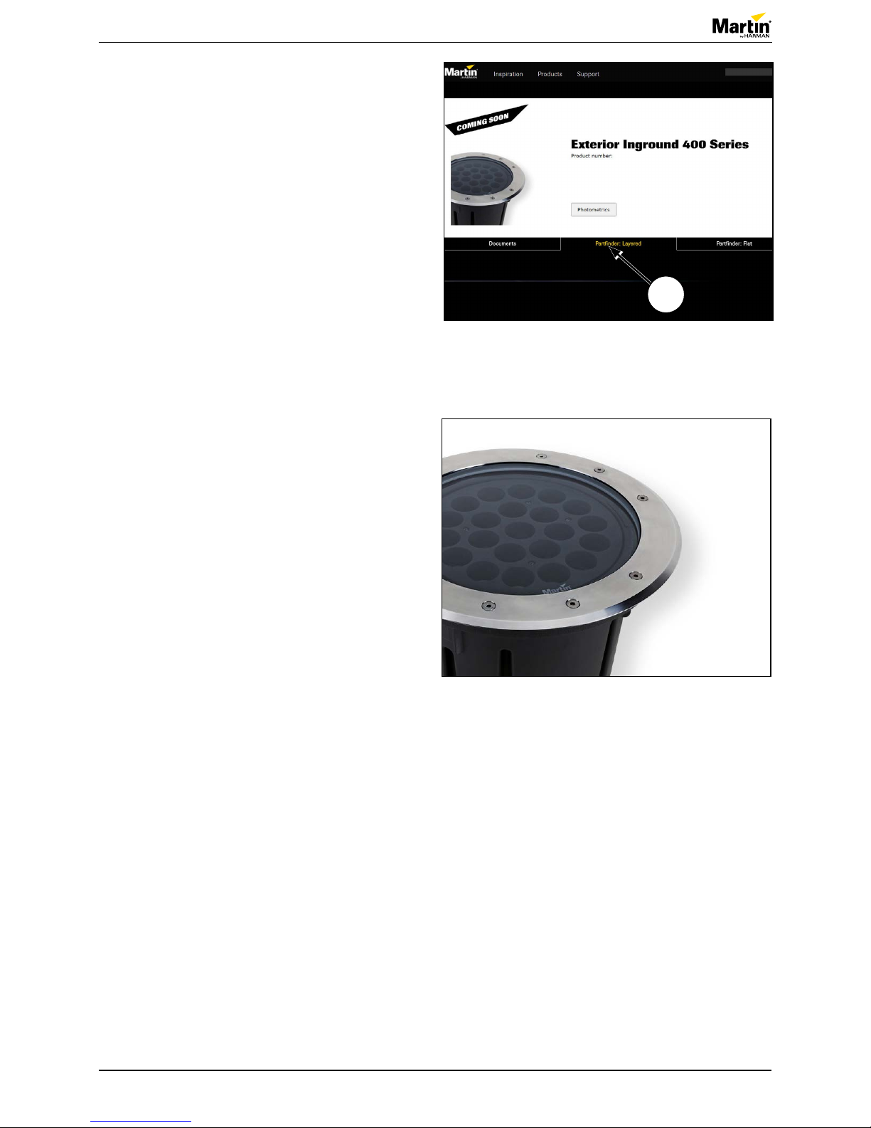
Figure 3: ESD mat and wristband
Take the necessary precautions
to prevent static electricity from
damaging the product during
modication or repair.
Service manual
4 of 18Exterior Inground 400 LED - Revision B, 08-18-2017
Product information
Before you start servicing the product, do the following:
• Disconnect the xture from power and DMX.
• Make sure that all necessary tools and spare
parts are available before you open the xture.
• Only perform this task in dry conditions.
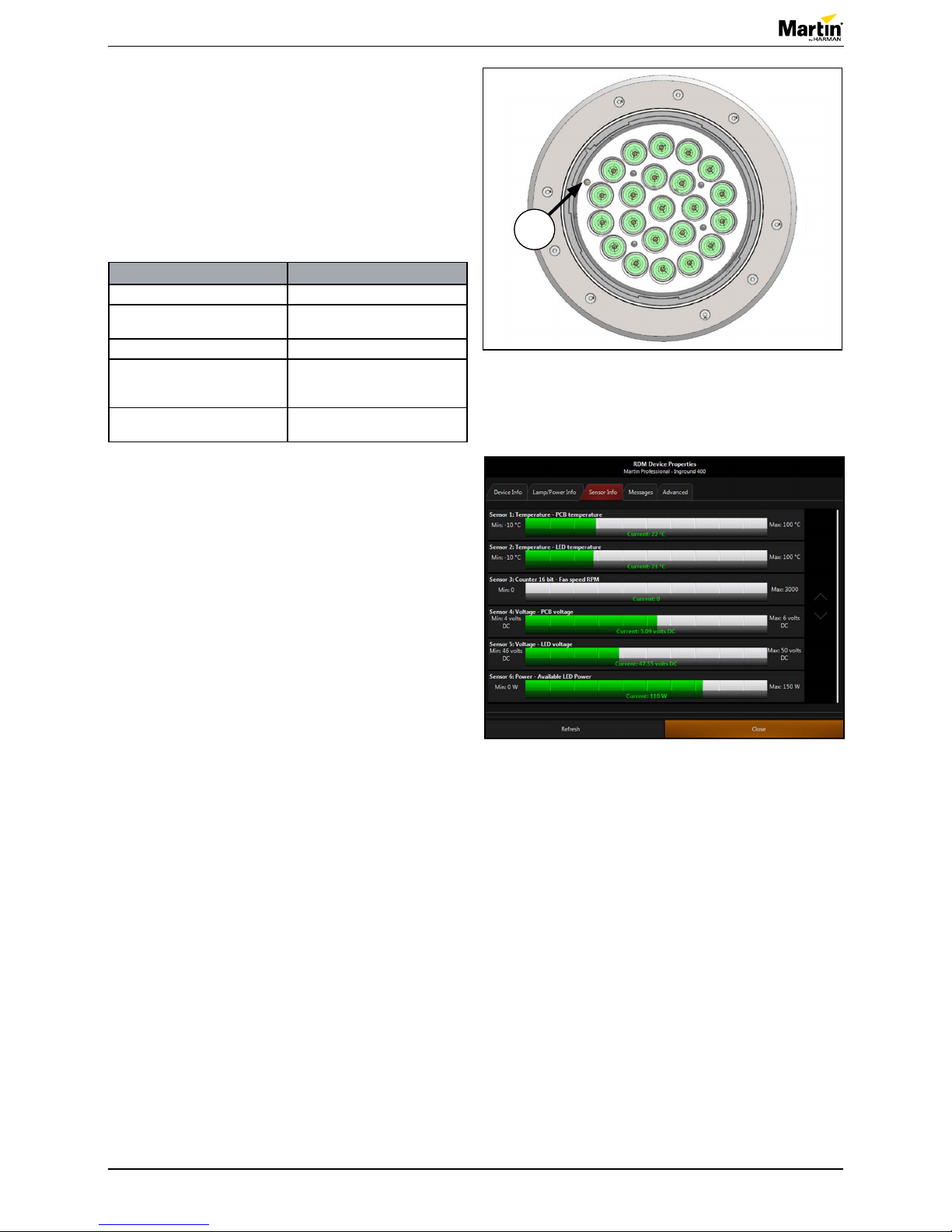
Figure 4: Partnder: Layered
Figure 5: Exterior Inground 400 LED
Spare parts
For an overview of the spare parts and spare part
numbers of Exterior Inground 400 LED, refer to
martin.com.
1. Login with your user login details.
2. Search for “Exterior Inground 400 LED”.
3. Clik “Partnder: Layered” (1).
You will need the following spare parts:
• The parts that are to be replaced.
• An anti-humidity bag (P/N 37220000).
1
Service manual
5 of 18Exterior Inground 400 LED - Revision B, 08-18-2017
Troubleshooting
Status indicator
A status LED (1) is situated close to the edge of the
main LED array under the top glass. To see the status
LED, look directly down through the top glass from
close to the xture.
The LED gives the following information about the
xture status:
LED signal Fixture status
LED ashes. No valid DMX signal is present.
LED is constantly on. Fixture receives valid DMX
signal.
LED is green. Normal status.
LED is red. Fixture reports error. Check the
xture status via RDM*. See
gure 7.
LED is yellow. Fixture is in boot mode for
rmware update**.
* You can use RDM to send setup commands, check
the properties and view the status information of the
xture.
We recommend that you use a Martin™ M-PC to
congure the xture. Martin™ M-PC is an RDM
compatible DMX controller application that you can run
on a Windows PC. For more information about RDM,
see the user manual for the xture.
**You can update the rmware via a Martin™ Firmware
Uploader and a Martin™ USB DMX interface.
Figure 6: Status indicator LED
1
Figure 7: RDM readout
Service manual
6 of 18Exterior Inground 400 LED - Revision B, 08-18-2017
6 of 18
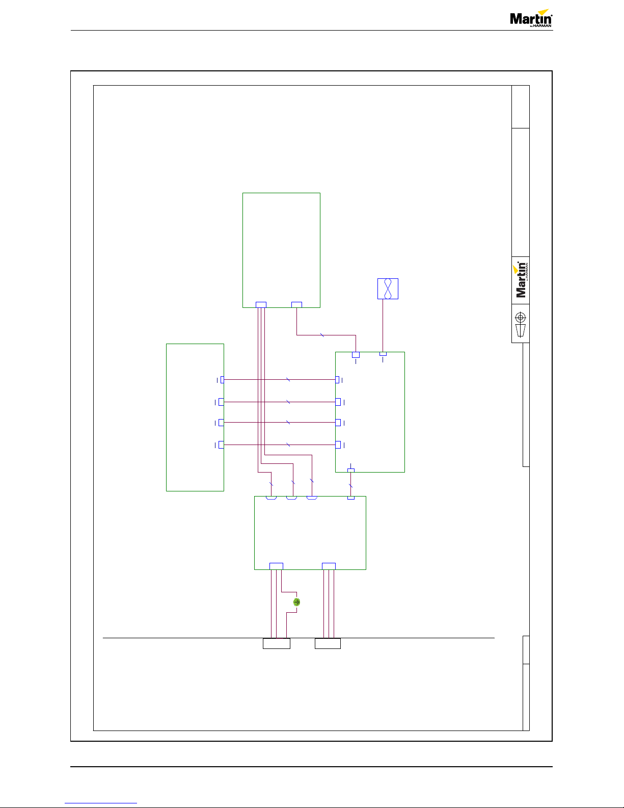
Wiring diagram
© 2017 Martin Professional ApS
Martin™ General Technical Specification apply to this item
Confidential
Page 1 of 1
Exterior Inground 400 LED
1
1
PG
PG
11851051
11865233
11865231
11865230
11865232
Wire on fan
PL1 PL2
PL1
PL2
PL1
PL2123
PL3 PL1 PL2
11521050 - EU
11521051 - US
11521050 - EU
11521051 - US
3
PL4
L
PL8
DMX
4
1
PL6
Fan
4
PL19
DMX mainboard
4
2
PL2
DMX5
62110092
PCBA Mainboard Ext. 400 XB series
PL1
Blue - White
4
4
PL2
Green - Red
4
2
PL1
Mains4
PL3
N
PL4
White
4
62110109
PCBA, Pixel InGround MKII
1
62110110
PCBA, AC Filter InGround MKII
PL3
I2C
5
1
4
PL5
Earth
4
PL1
LED1_2
4
FAN1
FAN
PL5
48V
2
PL18
48V
6
06150028
SMPS 32V/48V, 200W Complete
PL2
LED3_4
4
PL17
Mains
5
PL3
LED5
4
PL4
I2C
5
Figure 8: Wiring diagram, Exterior Inground 400 LED
 Loading...