

Martin Exterior 200 User Manual
martinarchitectural
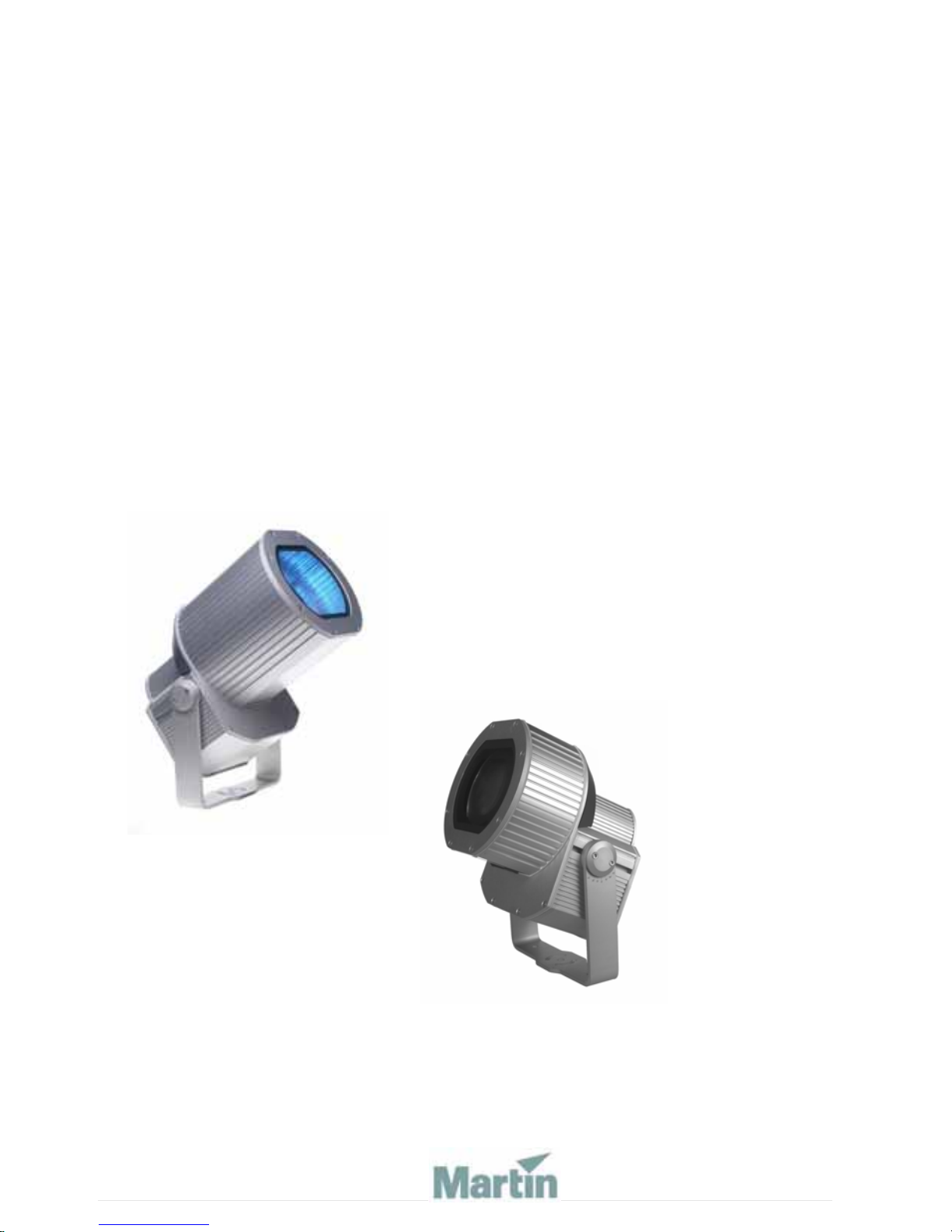
Exterior 200
user manual
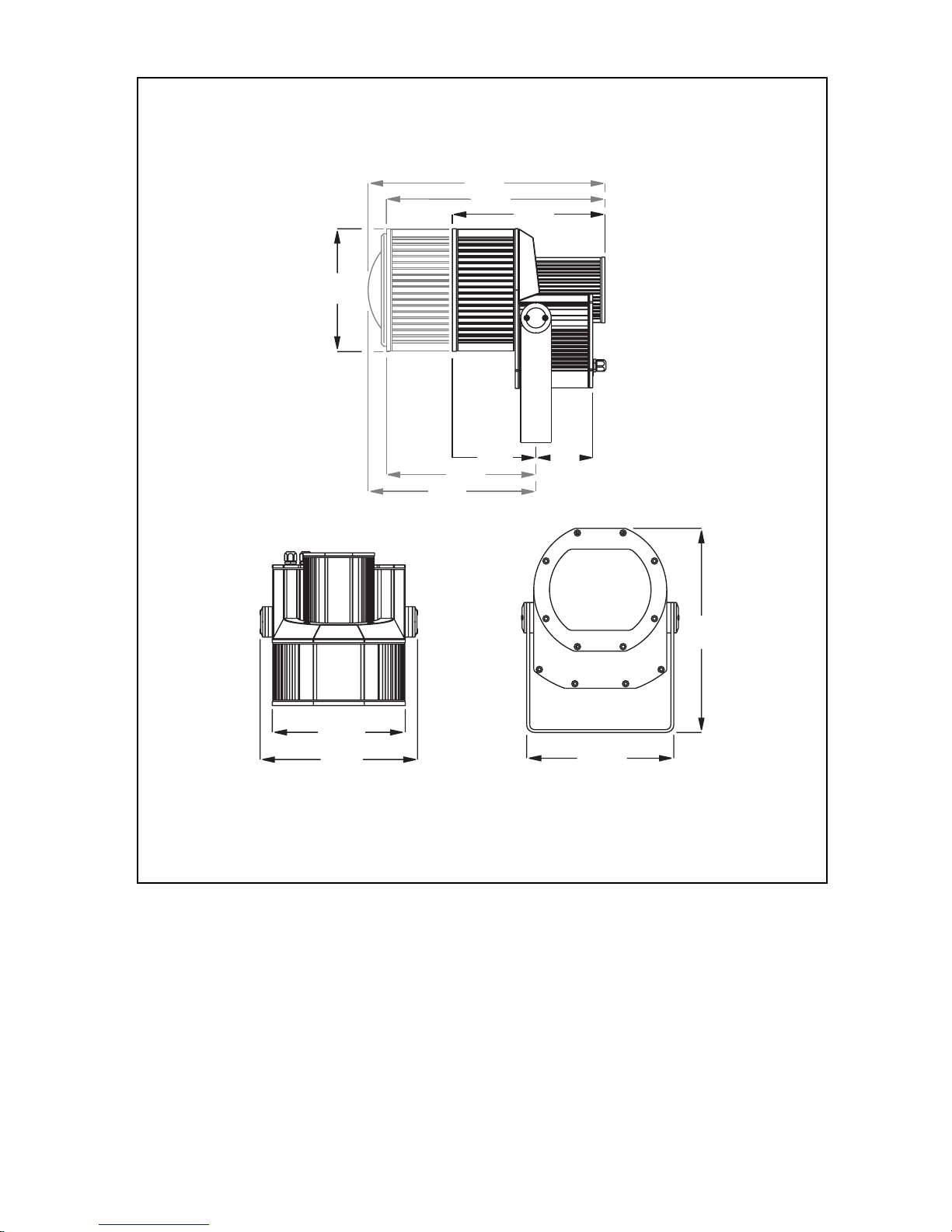
Measurements are in millimeters
467
431
242
301
262
310
331
295
165
112
402
290
© 2003-2006 Martin Professional A/S, Denmark.
All rights reserved. No part of this manual may be reproduced, in any form or by any means,
without permission in writing from Martin Professional A/S, Denmark. Information subject to
change without notice. Martin Professional A/S and all affiliated companies disclaim liability for
any injury, damage, direct or indirect loss, consequential or economic loss or any other loss
occasioned by the use of, inability to use or reliance on the information contained in this manual.
P/N 35000096, Rev. H

Contents
Section 1. Getting started . . . . . . . . . . . . . . . . . . . . . . . . . . . . . . . . . . . . . . 5
Introduction . . . . . . . . . . . . . . . . . . . . . . . . . . . . . . . . . . . . . . . . . . . . . 6
Software note. . . . . . . . . . . . . . . . . . . . . . . . . . . . . . . . . . . . . . . 7
Safety information . . . . . . . . . . . . . . . . . . . . . . . . . . . . . . . . . . . 7
Installation . . . . . . . . . . . . . . . . . . . . . . . . . . . . . . . . . . . . . . . . . . . . . .9
Unpacking . . . . . . . . . . . . . . . . . . . . . . . . . . . . . . . . . . . . . . . . . 9
Fastening method . . . . . . . . . . . . . . . . . . . . . . . . . . . . . . . . . . . 9
Fixture orientation and location . . . . . . . . . . . . . . . . . . . . . . . . 10
Bracket adjustment . . . . . . . . . . . . . . . . . . . . . . . . . . . . . . . . . 11
AC power . . . . . . . . . . . . . . . . . . . . . . . . . . . . . . . . . . . . . . . . . 11
Data link. . . . . . . . . . . . . . . . . . . . . . . . . . . . . . . . . . . . . . . . . . 15
Fixture settings . . . . . . . . . . . . . . . . . . . . . . . . . . . . . . . . . . . . . . . . . 17
Defining fixture settings using MUM. . . . . . . . . . . . . . . . . . . . . 18
Defining fixture settings using an MP-2 . . . . . . . . . . . . . . . . . . 21
General operation . . . . . . . . . . . . . . . . . . . . . . . . . . . . . . . . . . . . . . . 25
General guidelines. . . . . . . . . . . . . . . . . . . . . . . . . . . . . . . . . . 25
The LEDs and fixture operating status. . . . . . . . . . . . . . . . . . .25
Fixture control methods . . . . . . . . . . . . . . . . . . . . . . . . . . . . . . 26
Section 2. Stand-Alone operation . . . . . . . . . . . . . . . . . . . . . . . . . . . . . . 27
Stand-Alone programming overview. . . . . . . . . . . . . . . . . . . . . . . . 28
About scene timing. . . . . . . . . . . . . . . . . . . . . . . . . . . . . . . . . . 29
Synchronizing scene change s fo r multip le Exte rio r 20 0 s. . . . . 29
Programming methods. . . . . . . . . . . . . . . . . . . . . . . . . . . . . . . 30
Programming from a PC using MUM . . . . . . . . . . . . . . . . . . . . . . . . 31
Getting started . . . . . . . . . . . . . . . . . . . . . . . . . . . . . . . . . . . . .31
Stand-Alone Settings . . . . . . . . . . . . . . . . . . . . . . . . . . . . . . . . 32
Programming effects in scenes . . . . . . . . . . . . . . . . . . . . . . . . 34
Programming the same stand-alone show on multiple fixtures 36
Programming using an MP-2 Uploader . . . . . . . . . . . . . . . . . . . . . .37
Getting started . . . . . . . . . . . . . . . . . . . . . . . . . . . . . . . . . . . . .37
Selecting fixtures to program . . . . . . . . . . . . . . . . . . . . . . . . . . 38
Enabling or disabling stand-alone mode . . . . . . . . . . . . . . . . . 39
Synchronizing scene change s fo r multip le Exte rio r 20 0 s. . . . . 39
3

Automatically triggering stand-alone operation . . . . . . . . . . . . 40
Programming effects in scenes . . . . . . . . . . . . . . . . . . . . . . . .42
Automatic program start at power-on. . . . . . . . . . . . . . . . . . . .43
Disconnecting the MP-2 Uploader . . . . . . . . . . . . . . . . . . . . . .43
Stand-Alone show playback. . . . . . . . . . . . . . . . . . . . . . . . . . . . . . . 44
Starting show playback automatically at fixture power-on . . . . 44
Scene execution using the optional MC-X . . . . . . . . . . . . . . . .44
DMX controller override during stan d-alo n e sh ow pla yb ac k . .45
Synchronous triggering during Stand-Alone operation. . . . . . . . . 46
Section 3. DMX control. . . . . . . . . . . . . . . . . . . . . . . . . . . . . . . . . . . . . . . .49
DMX Controller operation . . . . . . . . . . . . . . . . . . . . . . . . . . . . . . . . . 50
Lamp control . . . . . . . . . . . . . . . . . . . . . . . . . . . . . . . . . . . . . . 50
Effects . . . . . . . . . . . . . . . . . . . . . . . . . . . . . . . . . . . . . . . . . . . 51
Section 4. Optics . . . . . . . . . . . . . . . . . . . . . . . . . . . . . . . . . . . . . . . . . . . . .53
Color matching Exterior 200s and 600s. . . . . . . . . . . . . . . . . . . . . . 54
Lens options. . . . . . . . . . . . . . . . . . . . . . . . . . . . . . . . . . . . . . . . . . . . 55
Changing the lens . . . . . . . . . . . . . . . . . . . . . . . . . . . . . . . . . . 55
Changing the front glass . . . . . . . . . . . . . . . . . . . . . . . . . . . . . 56
Section 5. Service and troubleshooting. . . . . . . . . . . . . . . . . . . . . . . . .57
Service . . . . . . . . . . . . . . . . . . . . . . . . . . . . . . . . . . . . . . . . . . . . . . . . 58
Seal maintenance . . . . . . . . . . . . . . . . . . . . . . . . . . . . . . . . . . 58
Lamp replacement . . . . . . . . . . . . . . . . . . . . . . . . . . . . . . . . . . 60
Cleaning. . . . . . . . . . . . . . . . . . . . . . . . . . . . . . . . . . . . . . . . . . 61
Firmware updates . . . . . . . . . . . . . . . . . . . . . . . . . . . . . . . . . . 61
Fuse replacement . . . . . . . . . . . . . . . . . . . . . . . . . . . . . . . . . . 62
Printed circuit board layout . . . . . . . . . . . . . . . . . . . . . . . . . . . . . . . 63
Troubleshooting. . . . . . . . . . . . . . . . . . . . . . . . . . . . . . . . . . . . . . . . .64
Section 6. Reference . . . . . . . . . . . . . . . . . . . . . . . . . . . . . . . . . . . . . . . . . .65
MP-2 control menu structure . . . . . . . . . . . . . . . . . . . . . . . . . . . . . .66
DMX protocol . . . . . . . . . . . . . . . . . . . . . . . . . . . . . . . . . . . . . . . . . . . 69
Specifications - Exterior 200. . . . . . . . . . . . . . . . . . . . . . . . . . . . . . . 70
4

S
ECTION
1. G
ETTING STARTED
5

Introduction
Thank you for selecting the Martin Exterio r 200. The Exterior 200 is an
automated 150 watt color-changing floodlight designed for fixed exterior
installation. It features seamless cyan, magenta, yellow (CMY) color mixing
and full-range continuous dimming. The fixture may be operated with DMX
controllers or in stand-alone mode with programmable start and stop times
or light levels.
An Exterior 200 running a pre-programmed show can perform synchronized
scene changes with up to 31 other Martin fixtures of the following types:
• Exterior 200
• Exterior 600
• FiberSource CMY150
• Imager series
• Alien 02 series
•MiniMAC Maestro
Exterior 200 models
The Exterior 200 is available in three models:
Beam angle: Configured for local supplies:
60° 230V/50Hz, 245V/50Hz, or 210V/60Hz
Exterior 200 Long Barrel models
The Exterior 200 Long Barrel is available in six models:
Beam angle: Configured for local supplies:
12° 230V, 50Hz, 245V/50Hz, or 210V/60Hz
22° 230V/50Hz, 245V/50Hz, or 210V/60Hz
Optional beam angles
The following optional lens are available for Exterior 200 models:
• Fresnel lens (provides a 34° beam angle in a standard Exterior 200)
• Micro diffuser lens (provides a 71° beam angle in a standard Exterior 200)
• Beam shaper (provides a 83° x 91° beam angle in a standard Exterior 200
and a 14° x 69° beam angle in an Exterior 200 Long Barrel)
6Introduction

Software note
The functions described in this manual are valid from Version 2 of the
Exterior 200 software. When running earlier versions of the software you
can to refer to an earlier revision of this user manual. These are available
from http://www.martin.com.
Safety information
Warning! This product is not for household use.
This product presents risks of lethal or severe injury due to fire and heat,
electric shock, ultraviolet radiati on, lamp explosion, and fall s. Read this
manual before powering or ins talling the fixture, follow the safety
precautions listed below and observe all warnings in this manual and on the
fixture. If you have questions about how to operate the fixture safely, please
contact your Martin dealer or call the Martin 24-hour service hotline at +45
70 200 201.
Guarding against electric shock
• Disconnect the fixture from AC power before removing or installing the
lamp, fuses, or any part.
• Always ground (earth) the fixture electrically.
• Use only a source of AC power that complies with local building and
electrical codes and has both overload and ground-fault protection.
• Refer all service to a Martin service technician.
Preventing UV radiation and lamp explosion
• Never operate the fixture with missing or damaged lenses and/or covers.
• When replacing the lamp, allow the fixture to cool for at least 15 minutes
before opening the fixture.
• Do not stare directly into the light. Never look at an exposed lamp while it is
lit.
• Replace the lamp if it becomes defective or worn out.
Guarding against burns and fire
• Never attempt to bypass the thermostatic switch or fuses. Always replace
defective fuses with ones of the specified type and rating.
Introduction 7

• Keep all combustible materials (for example fabric, wood, paper) at least 1
meter (39 inches) away from the fixture. Keep flammable materials well
away from the fixture.
• Do not illuminate surfaces within 0.5 meters (20 inches) of the fixture.
• Install the fixture outdoors or in a well ventilated area.
• Never place filters or other materials over the lens.
• The exterior of the fixture becomes very hot, up to 90° C (194° F) during
normal operation. Do not locate the fixture in areas where accidental contact
is likely.
• Do not modify the fixture or install other than genuine Martin parts.
• Do not operate the fixture if the ambient temperature (T a) exceeds 40° C
(104° F).
Preventing injury due to falls
• When suspending the fixture above ground level, verify that the structure is
able to support the weight of all installed devices and hardware.
• Block access below the work area whenever installing or removing the
fixture.
8Introduction
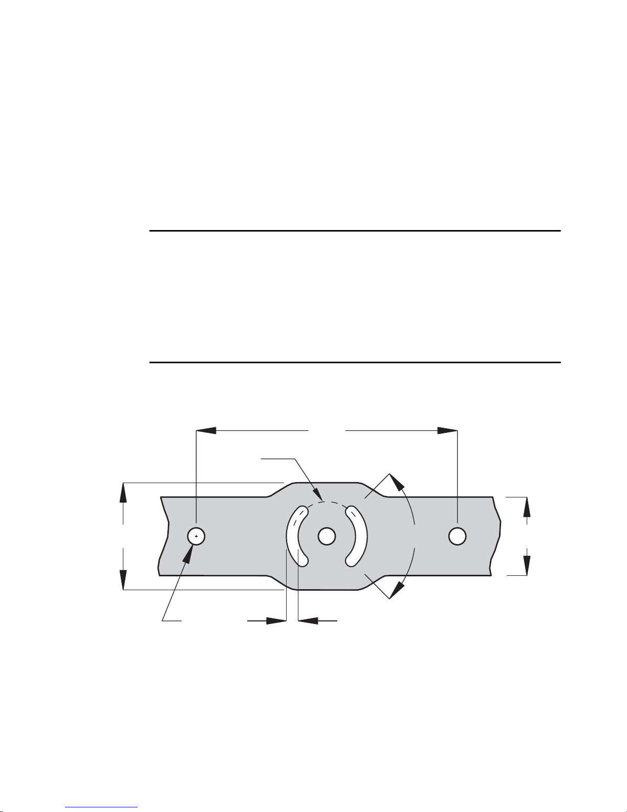
Installation
200
Ø53
82
Ø13
9
60
90°
This section describes in general terms how to mount the fixture and
connect it to data and AC power. These procedures shall be performed by
qualified professionals.
Unpacking
The Exterior 200 comes with the fol lo w i ng it ems:
• Philips CDM-SA/T 150 W discharge lamp (installed)
• User manual
Fastening method
Notice! It is the installer’s responsibility to determine the anchoring
method.
The Exterior 200 may be permanently fastened to any flat surface, pedestal,
or other support that can safely bear the weight of all installed fixtures and
hardware.
The mounting bracket provides 3 h oles for 12 mm (1/2 in.) hardware,
spaced 100 mm on center, and 2 quarter-circle slots with a center radius of
26.5 mm for 8 mm (5/16 in.) hardware.
Installation 9
Consult a qualified engineer to determine a suitable an choring method. T he
specific fastening hardware will depend on the installation. In genera l, use
high quality metric grade 8.8 or better corrosion resistant screws such as
zinc-plated steel, and self-locking nuts or lock-washers to secure the fixture.
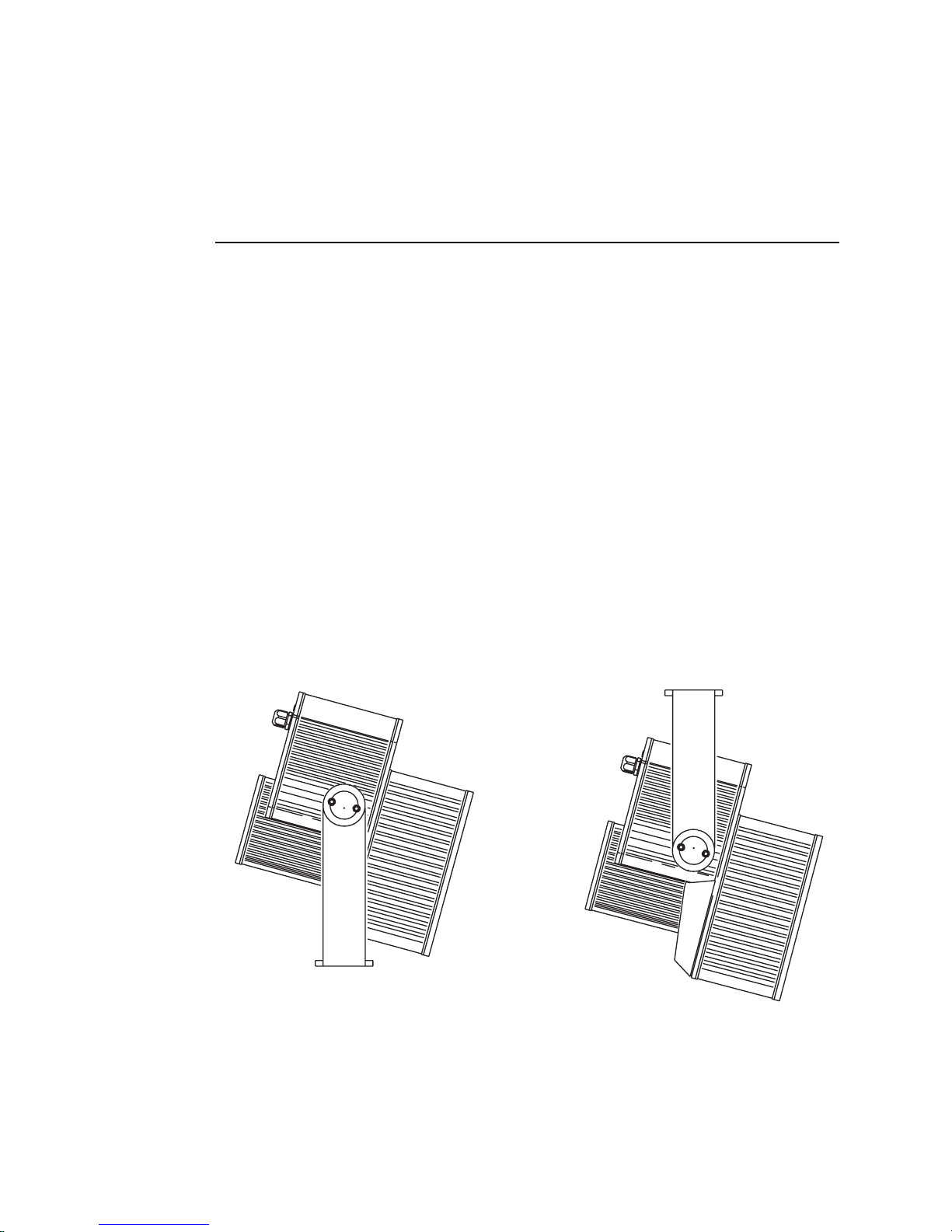
Fixture orientation and location
When choosing a location for the fixture, consider that it has an ingress
protection rating of 65. This means that the fixture is totally dust proof and
that it is protected from water ingression to the level that moisture fro m lowpressure water jets from any direction cannot get into the product. However,
the product is not designed to withstand:
• High-pressure water jets from any direction
• Immersion in water (or any other fluid)
Do not bury the Exterior 200 or other wise locate it in an unventilated space.
Install the fixture in a location where it is
• at least 0.5 meters (20 inches) away from the surface to be illuminated,
• at least 1 meter away from any combustible materials, and
• away from accidental public contact.
If the fixture points down, it must be installed with the power section over the
lamp section as shown so that water cannot collect between the lamp
section and the power section.
When the fixture is located above the area to be illuminated, install with
the power section on top.
10 Installation
Bracket adjustment
The mounting bracket can be positioned along the length of the power
section and pivots +70/-210 degrees from the 6 o’clock position shown
inside front cover.
This procedure requires 4 mm and 5 mm Allen wrenches (hex keys).
Warning! Allow the fixture to cool before handling.
To adjust the mounting bracket:
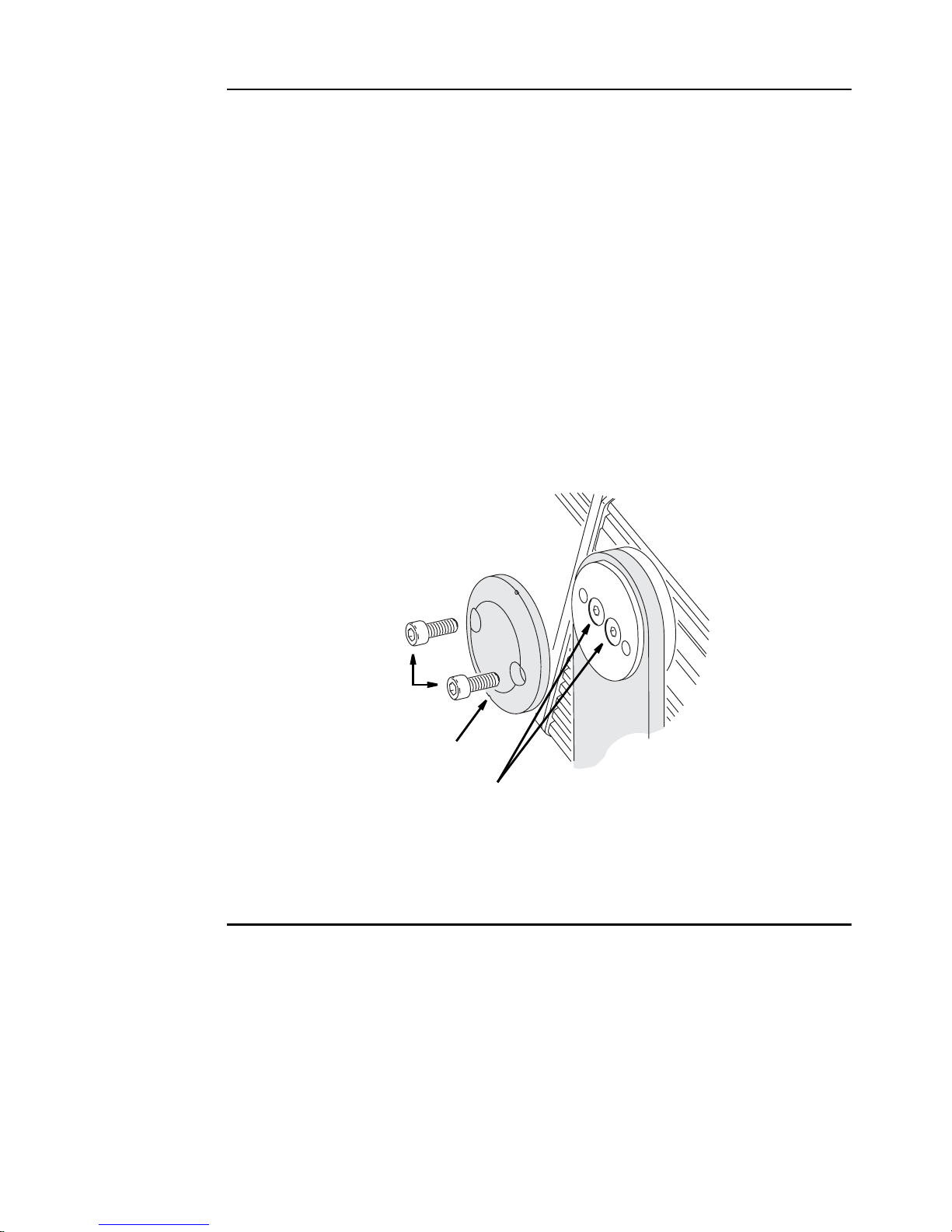
1 To adjust the bracket’s lateral position, remove the outer discs on each side
of the bracket. Loosen, but do not remove, the bracket screws. Slide the
fixture to the desired position and retighten the bracket screws. Replace the
outer discs.
2 To adjust the tilt angle, loosen the tilt-lock screws. Turn the fixture to the
desired angle and retighten the screws.
tilt-lock screws
outer disc
bracket screws
AC power
Do not connect the Exterior 200 to an electrical dimmer system: doing so
can damage the electronics.
Warning! Disconnect the fixture from AC power before removing any
cover.
Important! Verify voltage and frequency settings before applying power.
Installation 11
Power supply settings
Your Exterior 200 is factory-wired to one of the configurations shown in
Table 1. The factory settings are printed on the serial number label. If your
local AC voltage or frequency differ from the settings for your model, the
fixture’s power supply must be rewired by a qualified installer or technician.
Voltage Frequency
230 V 50 Hz
245 V 50 Hz
210 V 60 Hz
Table 1: Default Power Supply Settings
Changing the power supply se ttings
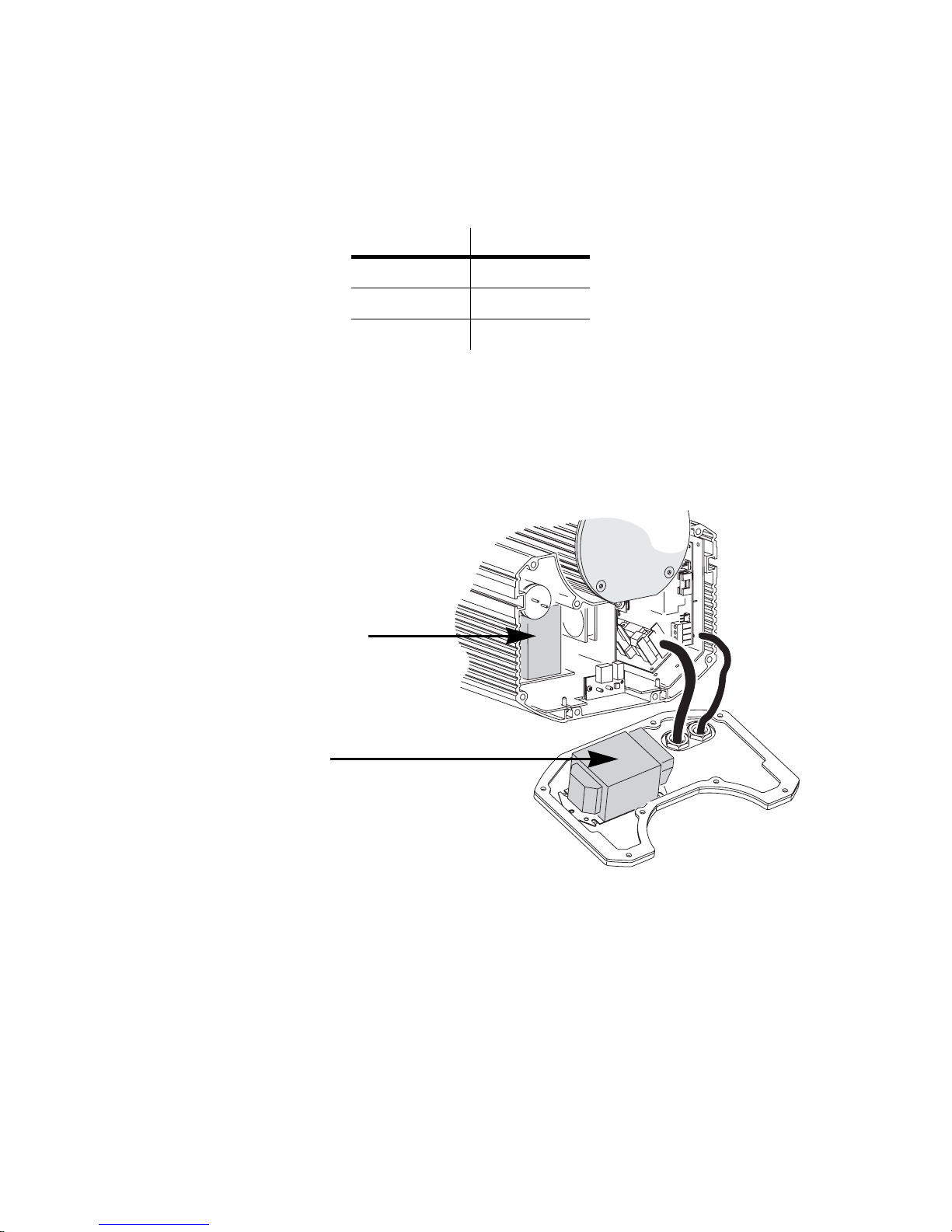
1 Verify that the Exterior 200 is isolated from AC power. Remove the rear
cover.
Transformer:
Move brown wire to
change AC voltage setting.
Ballast:
Move black wire to change
AC frequency sett ing.
2 Find the correct transformer setting for the local AC voltage in T able 2. Move
the brown transformer wire to the tap listed for the setting.
12 Installation
AC Mains
voltage
Transformer
setting
Tap, brown
wire
Tap, white &
blue wires
Tap, black
wire
190 - 202 V 195 V 11 9 14
203 - 217 V 210 V 12
218 - 235 V 225 V 14
236 - 252 V 245 V 15
269 - 285 V 277 V 16
Table 2: Transformer Primary Taps
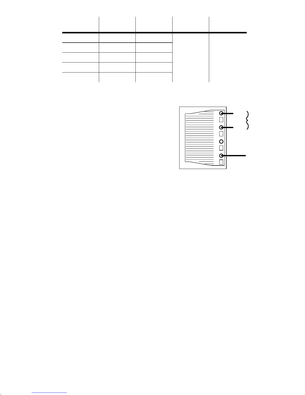
3 Set the correct AC frequency on the
ballast (located on the back of the
rear cover) by moving the black
50 Hz
black wire
60 Hz
ballast wire to the 50 or 60 Hz
terminal. (To release the wire, insert
a screwdriver in the hole next to the
brown wire
terminal.) Make sure the wire is
securely connected.
To set the frequency, move the
4 Replace the rear cover before
applying power. See “Seals and
black wire to the 50 or 60 Hz
terminal.
torque settings” on page 58.
Mains connection
Warning! For protection from dangerous electric shock, the fixture must
be grounded (earthed). The AC mains supply shall be fitted with
a fuse or circuit breaker, ground-fault protection, and a means
to isolate the fixture from the mains during service or when not
in use.
The fixture is supplied with a weatherproof power cable.
However, note that if there is a breach or cut at any point along
the power cable (for example at a connection point), and if this
is exposed to water, moisture can be drawn up the inside of the
cables due to the vacuum effect from the heat generated during
operation. When installing the product outdoors, always ensure
that the fixture is protected from water ingression from inside
its power cable by:
• Protecting the connectors on the power cables in a weatherproof
housing, or a weatherproof electrical junction box, or
• Using IP65 rated cord caps, or
Installation 13
• Replacing the supplied cable with one that connects directly inside the
fixture.
The Exterior 200 is equipped with a 1.8-meter (5.9 ft.) length of 3-conductor
0.75 mm
2
(~18 AWG) weatherproof electrical cable for connection to the AC
power supply . The cable enters the fixture through a cable gland that fits 5.5
- 10 mm diameter cables. The cable attaches with 1/4” female spade plugs
on the live and neutral wires and a ring terminal on the ground wire.
Replacing the mains lead
Other cable can be instal l e d as fo l lo w s.
1 Isolate the fixture from AC power.
2 Loosen both cable gland cap nuts and remove the power section cover.
Disconnect the existing mains cable and pull it through the cable gla nd.
3 Pass the new cable through the cable gland and connect the leads. The live
wire connects to PL3, the neutral wire connects to PL1, and the ground wire
connects to the chassis screw terminal.
4 Draw up the slack in the AC a nd data cables and re place the power secti on
cover. Tighten the cable gland cap nuts well to seal against moisture.
Installing a cord cap on the mains lead
A non-IP-rated cord cap may be installed on the mains lead for testing,
service, and temporary applications. For outdoor installations an IP65-rated
cord cap can be used.
Following the cord cap manufacturer’s instructions, connect the yellow and
green wire to ground (earth), the brown wire to live, and the blue wire to
neutral. Table 3 shows some pin identification schemes; consult an
electrician if you have any doubts about proper installation.
Wire (EU) Wire (US) Pin Marking Screw (US)
brown black live “L” yellow or
brass
blue white neutral “N” silver
yellow/green green ground green
14 Installation
Table 3: Cord Cap Connections

Data link
A data link is required for DMX controller operation, and for synchronized
stand-alone operation of multiple Exterior 200s.
Cable and junctions
The Exterior 200 provides a dual 1.8 meter (5.9 ft.) 24 AWG cable with
locking 3-pin male and female XLR co nnectors for data connection. The
male cable is the data input and the female cable is the data output. The
connectors are wired pin 1 to shield (gnd.), pin 2 to signal - (cold), and pin 3
to signal + (hot).
Use RS-485 data cable designed for outdoor use to extend the link. RS-485
cable has low capacitance and a characteristic impedance of 85 to 150
ohms. It is electrically shielded and has at least 1 twisted-pair of conductors.
The minimum wire size is 0.2 mm
(1000 ft.) and 0.35 mm
Warning! The fixture is not supplied with a weatherproof XLR co n nec to rs .
If these connectors are exposed to water, moisture can be
drawn up the inside of the cables due to the vacuum effect from
the heat generated during operation. When installing the
product outdoors, always ensure that the fixture is protected
from water ingression from inside its data cable by:
2
(22 AWG) for runs up 500 meters (1640 ft.).
2
(24 AWG) for runs up to 300 meters
• Protecting the connectors on the data cable in a weatherproof housing
(or a weatherproof electrical junction box), or
• Using IP65 rated XLR cable and connectors (such as those produced
by Neutrik), or
• Replacing the supplied cable with one that connects
directly inside the fixture. This option requires a new
cable gland, see “Cable glands” on page 59. The
leads connect to the main circuit board as shown to
right.
ground
hot (white)
cold
not used
CB data
onnections
Installation 15
Adaptors
Adaptors may be required to connect the Exterior 200 to the controller or
other 5-pin devices. Adaptor cables for indoor use are available from Martin.
The adaptor cables are wired as shown below.
5-pin to 3-pin
Adaptor
Male Female
1
2
3
4
5
P/N 11820005
1
2
3
3-pin to 5-pin
Adaptor
Male Female
1
2
3
P/N 11820004
1
2
3
4
5
Splitter/Amplifiers
A device such as the Martin 4-Channel Opto-Isolated RS-485
Splitter/Amplifier may be used to branch the data link and/or extend its
length. Do not use a “Y” connector to split the link.
Terminators
Termination of the data link is required for trouble-free communication. For
temporary installations, this can be achieved with a male termination plug
inserted into the data output cable of the last fixture in each chain. A
termination plug is simply an XLR connector with a 120 ohm resistor
soldered across pins 2 and 3.
For permanent terminations, the link can be terminated with a 120 ohm
resistor across the hot and cold data terminals at the main circuit board
inside the last fixture in each chain.
Building a data link
To build a data link:
1 Connect a data cable to the controller’s data output. A male 5-pin to female
3-pin adaptor may be required. Lead the data cable from the controller to
the first fixture and plug it into the male data cable.
2 Connect the output of the fixture closest to the controller to the input of the
next fixture. Continue in this manner. Up to 32 fixtures may be connected
output to input.
3 Terminate the link as described abo ve, at the output of the last fixture in the
chain.
16 Installation
Fixture settings
This section describes how to set the control address, clock, and other
fixture personalities. There are three ways to define fixture settings:
Multi-Utility
Manager
Martin MP-2
Uploader
Multi-Utility Manager (MUM) is a PC software
application supplied with a DABS1 USB-to-XLR
communications adaptor. We recommend MUM
because it provides an intuitive, easy-to-use, graphical
user interface.
One limitation with MUM is that you can only connect
to, and set-up, one fixture at a time.
See “Defining fixture settings using MUM” on page 18.
This hardware uploader can be loaded with the Exterior
200’s control software and connected to the fixture or
data link. (Please refer to the MP-2 Uploader user
manual for details on how to do this).
When working with multiple fixtures an MP-2 allows you
to apply settings globally to multiple fixtures on a data
link.
The MP-2 provides a text-based interface and the
fixtures do not provide feedback to the uploader.
Therefore, the current settings of the fixture can only be
“read” by observing the behavior of the fixture.
See “Defining fixture settings using an MP-2” on page
21.
Fixture settings 17
DMX
Address
Device
DMX Address Device (DAD) is a hardware device that
can be used to set the DMX address of one Exterior
200 at a time.
If you need to set other fixture setting - such as the
internal clock - then you will also need to use an MP-2
or MUM to completely set-up the fixture.
Refer to the DMX Address Device user manual for more
information.
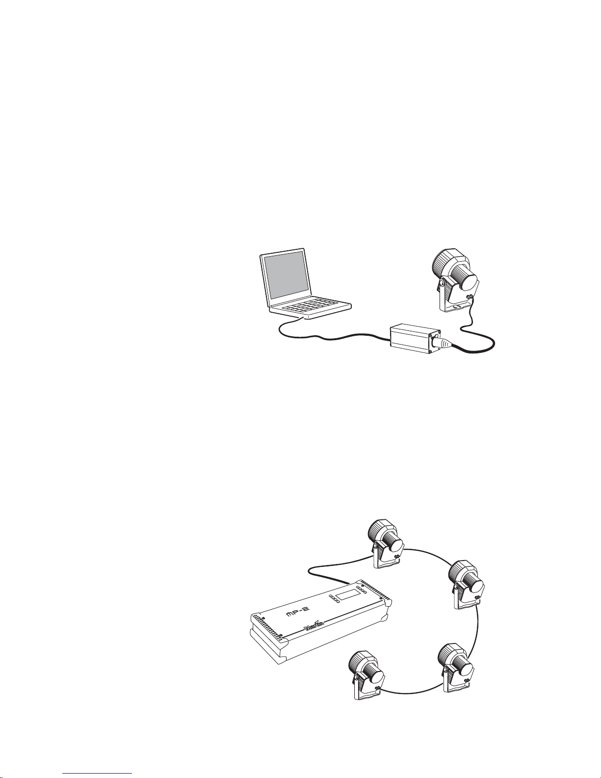
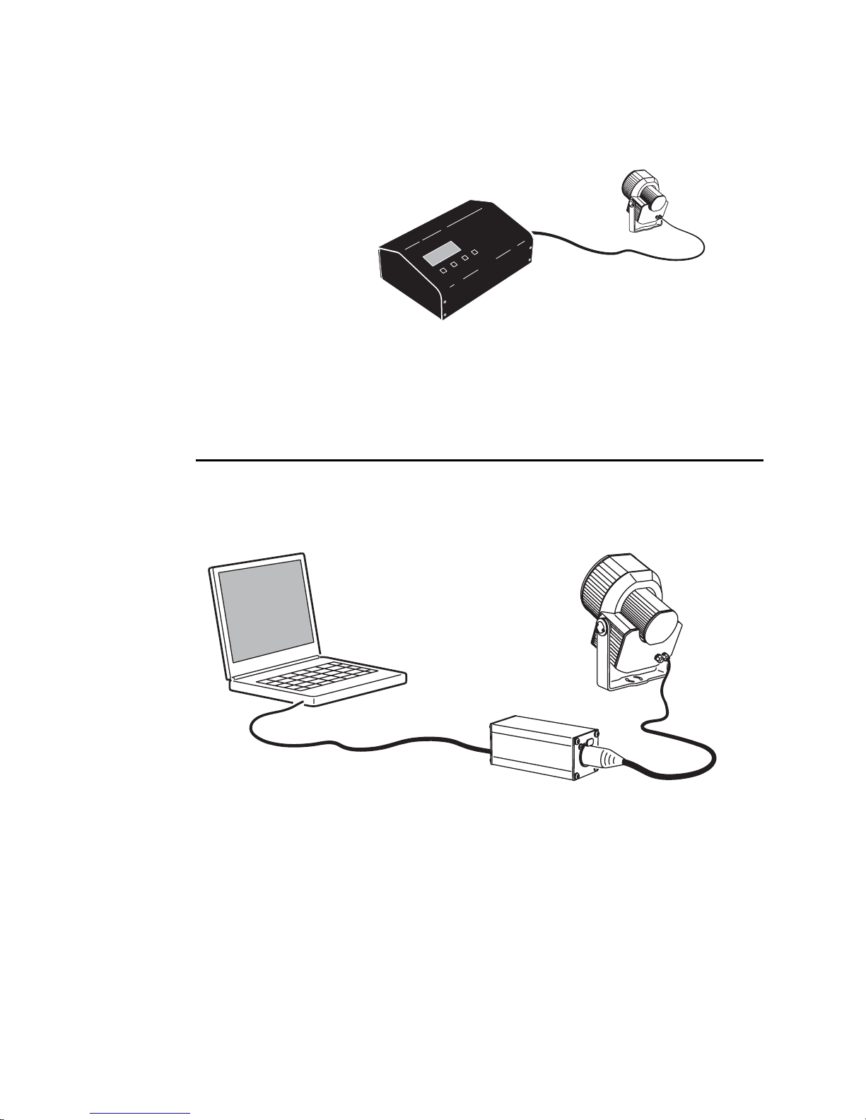
Defining fixture settings using MUM
Using the MUM you can connect to and set up one fixture at a time. Refer to
the MUM user manual for instructions on installing and starting the MUM
application.
PC
DABS1
Support for the MUM application is available from Version 2 of the Exterior
200 software.
To get started:
Exterior 200
1 Connect a DABS1 adaptor to your PC.
2 Connect the DABS1 adaptor to your Exterior 200.
3 Power on the Exterior 200 and start the MUM application. The application
will automatically detect an Exterior 200 if it is powered-on and connected to
your computer via a DABS1 adaptor. It will also retrieve the current settings
on the fixture and display them.
18 Fixture settings
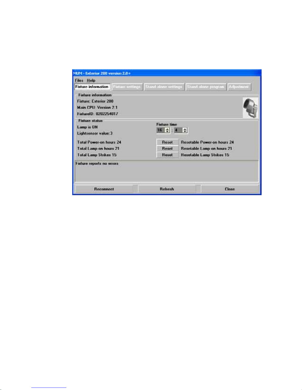
Clock
The Exterior 200 has a battery operated 24-hour clock that can start and
stop stand-alone operation.
To set the clock:
1 Using MUM, click on the Fixture information button:
2 Using the two Fixture time spin buttons set the fixture to the current time
(expressed in the 24-hour clock in hours and minutes). The time will be
updated in the fixture in real-time.
Fixture settings 19
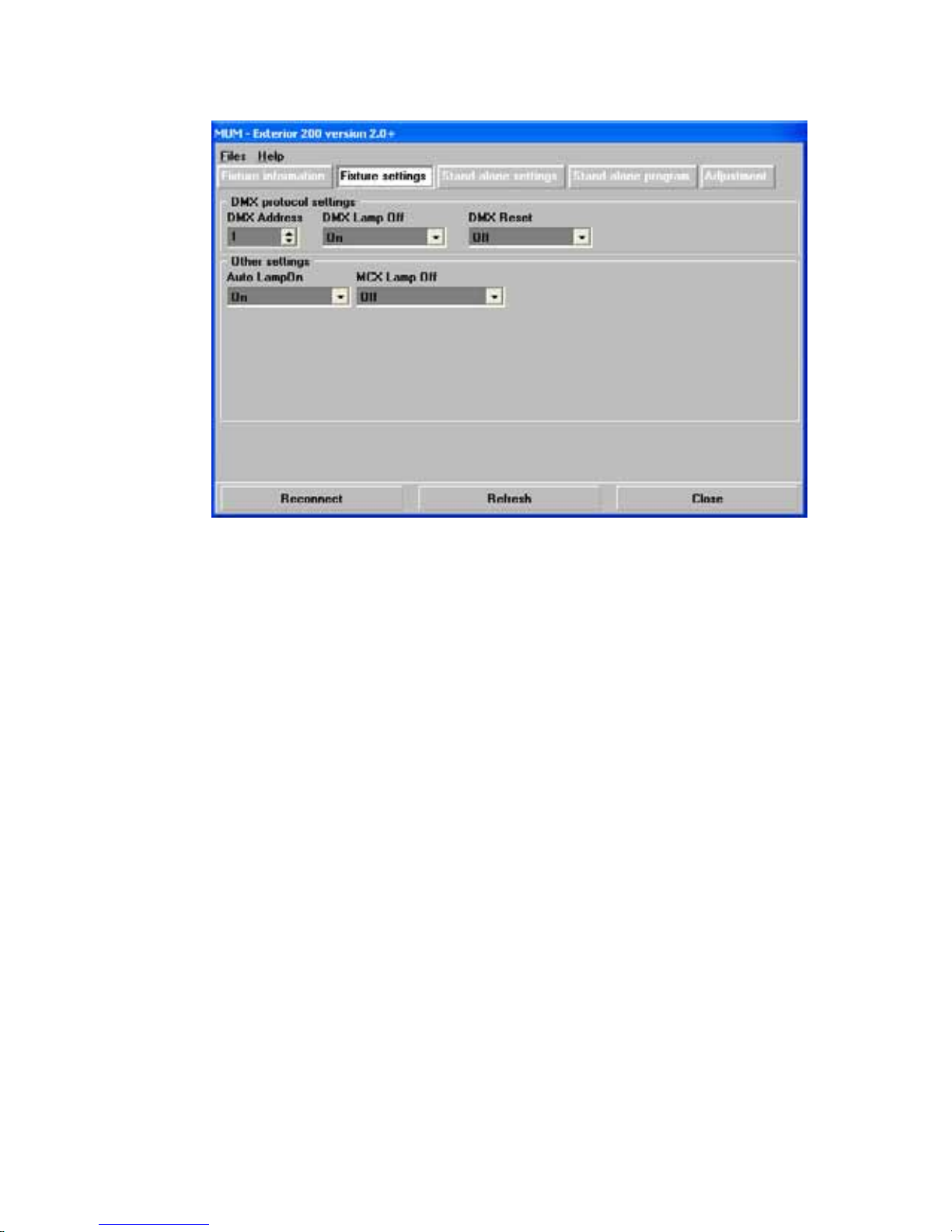
Fixture settings
To set the additional fixture settings, click on the Fixture settings button:
DMX address
The DMX address, also known as the control address, or start channel, is
the first channel used to receive instructions from the controller. Each fixture
needs its own control address set, and uses this address and subsequent
control channels to receive instructions from a controller. The Exterior 200
uses seven control channels.
The control address, also known as the start channel, is the first channel
used. The Exterior 200 uses seven channels of control data. It reads the
data on the start channel and the next six channels. If the control address is
set to 100, the fixture uses channels 100, 101, 102, 103, 104, 105, and 106.
Channel 107 would be the control address for the next fixture.
If two or more fixtures are set up with the same address, they will receive
the same instructions and should behave identically. Setting up identical
fixtures with the same address is a good tool for troubleshooting
unexpected behavior and an easy way to achieve synchronized action.
To set the DMX address use the DMX Address spin button. The fixture
address is updated in real time.
DMX Lamp Off
When the DMX Lamp-off personality is on (the default setti ng), lamp power
can be turned off from the controller by setting channel 1 to a decimal value
20 Fixture settings
from 248 to 255. When set to off, the lamp-off command executes only if
channels 3, 4, and 5 are set to values from 230 to 232.
DMX Reset
When the DMX Reset personality is on (the default setting), the fixture can
be reset from the controller by setting channel 1 to a decimal value from 208
to 217. When set to off, the reset command executes only if channels 3, 4,
and 5 are set to values from 230 to 232.
Automatic Lamp On
When the Automatic Lamp On personality i s on, the fixture turns on the
lamp within 90 seconds of power on. When set to off (the default setting), a
lamp-on command is required to turn on the lamp.
MC-X Lamp Off
By choosing the option MCX Preset 7 Key from the MCX Lamp off field
you enable button 7 on an MC-X controller to be used to control the lamp off
function.
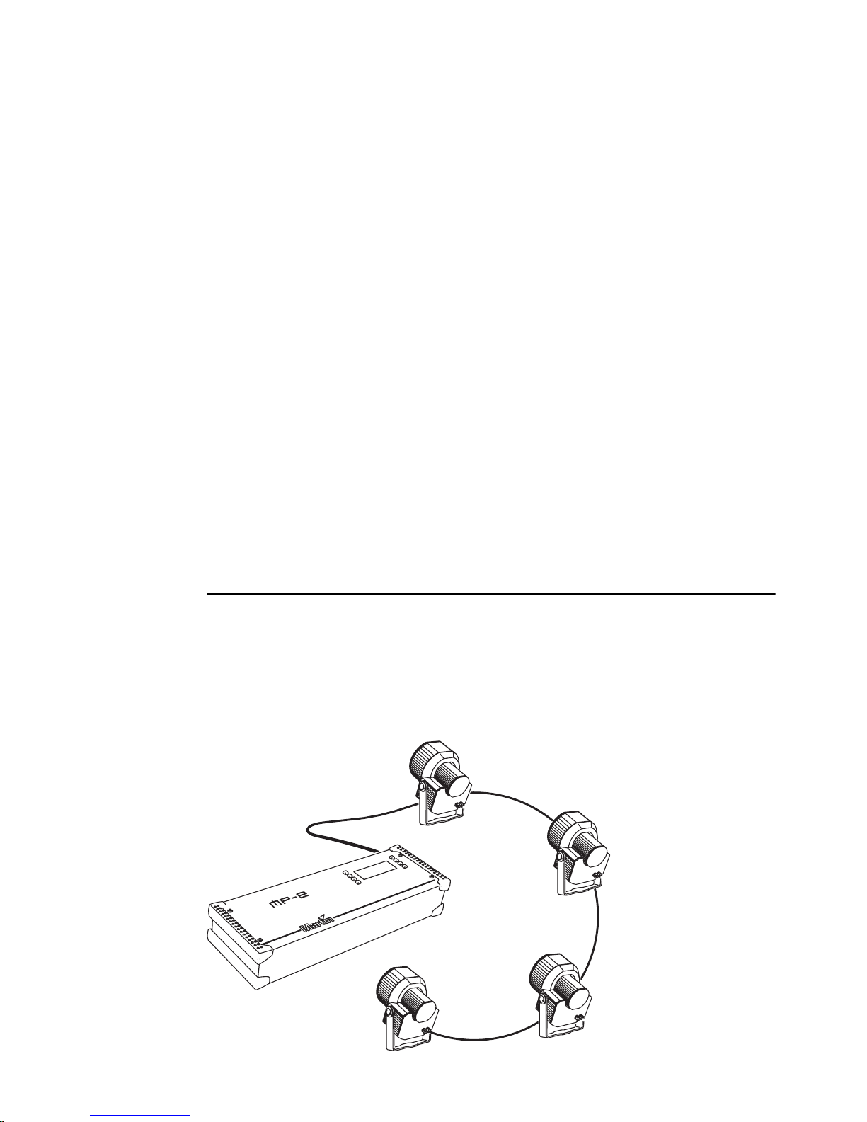
Defining fixture settings using an
MP-2
This hardware uploader can be loade d with the Exterior 200’s control
software and connected to a fixture or data link. (Please refer to the MP-2
Uploader user manual for details on how to do this).
When working with multiple fixtures an MP-2 allows you to appl y settings
globally to multiple fixtures on a data link.
Exterior 200s
MP-2
Fixture settings 21

The MP-2 provides a text-based interface and the fixtures do not provide
feedback to the uploader. Therefore, the current settings of the fixture can
only be “read” by observing the behavior of the fixture.
Modes
The uploader provides two ways to access fixtures: single-fixture mode and
all-fixtures mode. In single-fixture mode, the uploader communicates only
with the fixture at a designated address. In a ll-fixtures mode, the upload er
communicates with all fixtures, of the same type, to which it is connected.
Fixture-specific settings such as the control address should be made in
single-fixture mode. If no other fixtures are connected, however, then allfixtures mode may be used. Global settings are made easiest in all-fixtures
mode.
DMX address
The DMX address, also known as the control address, or start channel, is
the first channel used to receive instructions from the controller. Each fixture
needs its own control address set, and uses this address and subsequent
control channels to receive instructions from a controller. The Exterior 200
uses seven control channels.
The control address, also known as the start channel, is the first channel
used. The Exterior 200 uses seven channels of control data. It reads the
data on the start channel and the next six channels. If the control address is
set to 100, the fixture uses channels 100, 101, 102, 103, 104, 105, and 106.
Channel 107 would be the control address for the next fixture.
If two or more fixtures are set up with the same address, they will receive
the same instructions and should behave identically. Setting up identical
fixtures with the same address is a good tool for troubleshooting
unexpected behavior and an easy way to achieve synchronized action.
Important! When setting the address, either use single-fixture mode or
isolate all other fixtures from the uploader.
To set the control address:
1 Prepare an upload device as described in the uploader user manua l. If you
know the address to which the fixture is currently set, that is, the address to
change from, connect the uploader to the data link and use single-fixture
mode. Otherwise, use all -fixtures mode and isolate all other fixtures from
the uploader. Apply power to the fixture.
2 If using single-fixture mode, scroll to the fixture’s current (from) address and
press OK.
22 Fixture settings

3 Select DMX address from the fixture menu.
4 Scroll to the desired control address and press OK.
5 Press OK again to confirm and save the setting.
Personality settings
The following settings are available to modify fixture behavior.
DMX Lamp-off: When the DMX Lamp-off personality is on (the default
setting), lamp power can be turned off from the controller by setting channel
1 to a decimal value from 248 to 255. When set to off, the lamp-off
command executes only if channels 3, 4, and 5 are set to values from 230 to
232.
DMX reset: When the DMX Reset personality is on (the default setting), the
fixture can be reset from the controller by setting channel 1 to a decimal
value from 208 to 217. When set to off, the reset command executes only if
channels 3, 4, and 5 are set to values from 230 to 232.
Automatic Lamp-on: When the Automatic Lamp-on personality is on, the
fixture turns on the lamp within 90 seconds of power on. When set to off (the
default setting), a lamp-on command is required to turn on the lamp.
Clock
To set a personality setting:
1 Prepare and connect an upload device as described in the uplo ader user
manual. Apply power to the fixture.
2 Select single fixture mode to change a setting on a single fixture, or all-
fixtures mode to make global changes.
3 If using single-fixture mode, enter the fixture’s address.
4 Select
5 Select the desired personality and setting. (See “MP-2 control menu
structure” on page 66.) Press OK.
The Exterior 200 has a battery operated 24-hour clock that can start and
stop stand-alone operation.
To set the clock:
Special from the fixture menu.
1 Prepare and connect an upload device as described in the MP2 Upload er
manual. Apply power to the fixture.
2 Select all-fixtures mode.
3 Select
Time from the fixture menu.
Fixture settings 23
 Loading...