

Martin Exterior 1200 Wash User Manual
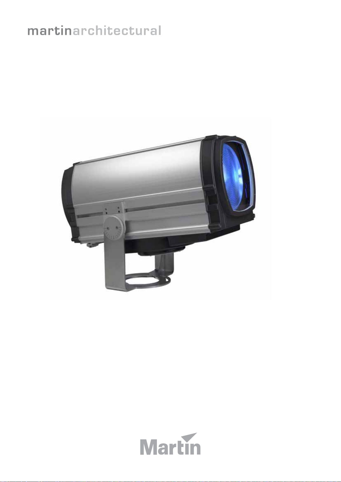
Exterior 1200 Wash
user manual
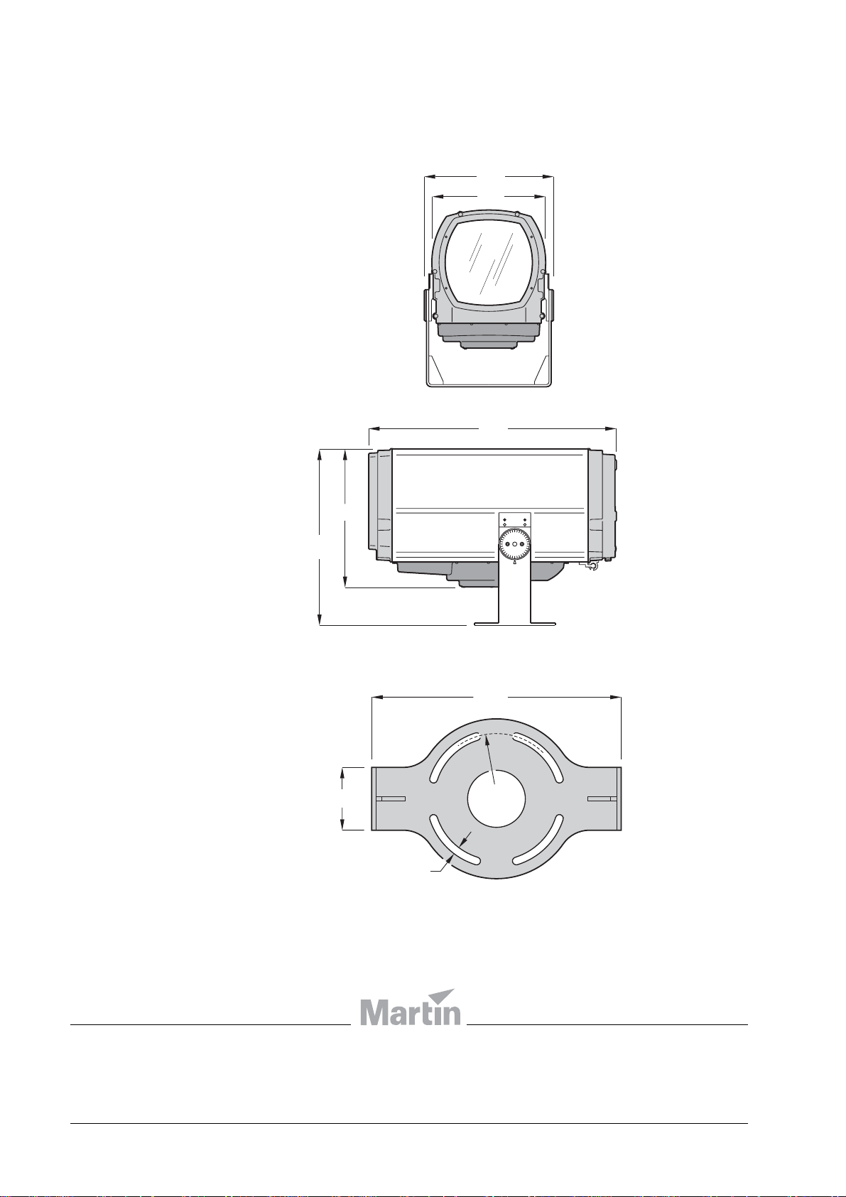
Dimensions
448
392
620
485
860
13
432
110
Ø247
Measurements are in millimeters
Luminaire
Mounting yoke base
© 2006 Martin Professional A/S. All rights reserved. No part of this manual may be reproduced, in any form or by any means, without
permission in writing from Martin Professional A/S. Information subject to change without notice. Martin Professional A/S and all
affiliated companies disclaim liability for any injury, damage, direct or indirect loss, consequential or economic loss or any other loss
occasioned by the use of, inability to use or reliance on the information contained in this manual. Please check with your Martin
Architectural supplier that you have the latest product information before installing or servicing this product.
P/N 35000177 Rev. B

Section 1. Safety
3
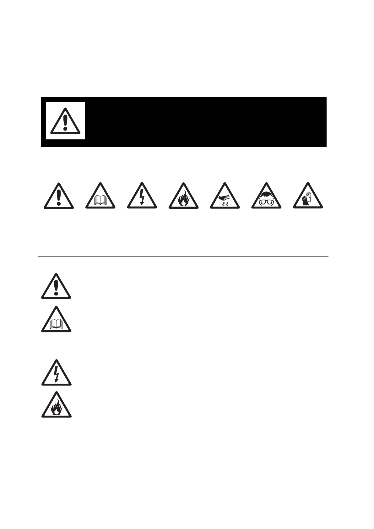
1.1 Safety information
WARNING!
Read the safety precautions in this section
before installing, powering, operating or
servicing this product.
The following symbols are used to identify important safety information on th e product and
in this manual:
DANGER!
Safety hazard.
Risk of severe
injury or death.
DANGER!
Refer to user
manual for
important
safety
information.
DANGER!
Hazardous
voltage. Risk of
lethal or severe
electric shock.
DANGER!
Fire hazard.
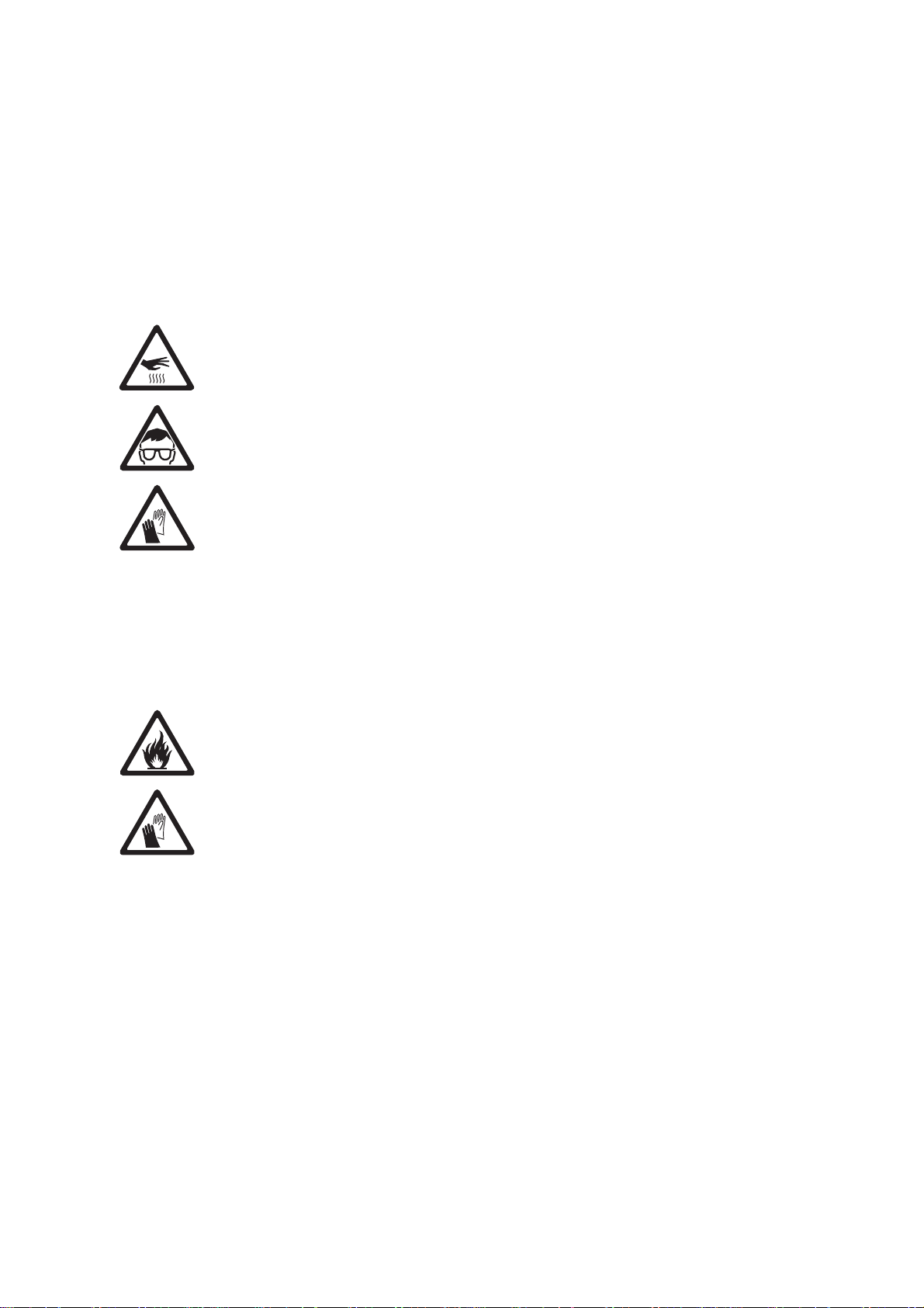
Warning!
Burn hazard.
Hot surface. Do
not touch.
Warning!
Risk of eye
injury . Safety
glasses must
be worn.
Warning!
Risk of hand
injury. Safety
gloves m ust be
worn.
DANGER! This product is for professional use only. It is not for household
use. If safety precautions are not followed, it presents risks of injury due to
electric shock, heat and ultraviolet radiation burns, lamp explosion, falls,
high-intensity light, and fire.
Read this manual before installing, powering, operating or servicing the
luminaire. Follow the safety precautions listed below, and observe all
warnings in this manual and on the luminaire. Use the luminaire only as
described in this manual and in accordance with local laws and regulations.
Refer any operation not described in this manual to a qualified technician.
Electrical safety
• Do not use the luminaire if any cable, component or cover is damaged, cracked or
deformed.
• Switch the lamp off, allow the luminaire to cool with fans running for 20 minutes, then
isolate it from AC power and lock out power before removing or installing the lamp,
fuses, or any part.
• Ensure that the luminaire is correctly configured for the local AC power voltage as
described in this manual before applying power for the first time.
• Always ground (earth) the luminaire electrically.
• Use only a source of AC power that complies with local building and electrical codes and
has both overload and ground fault (earth fault) protection.
4 Exterior 1200 Wash user manual
• The AC power distribution system must include a means of isolating all installed devices
from power and locking out power during service
• Ensure that all components in the AC powe r di stribu tio n cir cuits (cables, junction boxes,
etc.) are protected from water and airborne particles to IP67 or higher, are suitably
dimensioned for the current and power requirements of the devices inst alled , and ar e of
suitable type for the location (including water, pollution, temperature and UV resistance).
• Do not expose any part of the luminaire to a high-pressure water jet.
• Do not expose the heat exchanger to water projections.
• Do not immerse the luminaire in water or install it in a location where flooding may occur.
• Refer all service not described in this manual to a Martin service technician.
Lamp safety
• Do not operate the luminaire with missing or damaged covers, shields, lenses or
ultraviolet screens: an unshielded discharge lamp emits UV radiation that can cause
burns and eye damage.
• Do not stare directly into the light output. Never look at an exposed lamp while it is lit.
• A hot discharge lamp is under pressure and can explode without warning. Allow the
luminaire to cool for at least 20 minutes and protect yourself with safety glasses and
safety gloves before replacing the lamp or servicing the luminaire internals.
• If the quartz envelope of a discharge lamp is broken, the lamp releases a small quantity
of mercury and other toxic gases. If a discharge lamp explodes in a confined area,
evacuate the area and ventilate it thoroughly. Wear non-porous safety gloves when
handling a broken discharge lamp. Trea t br oken or used disch arge lamps as hazardous
waste and send to a specialist for disposal.
• Replace the lamp if it becomes visually deformed, damaged or in any way defective
• Replace the lamp at the latest when it reaches the limit of its average life as specified in
this manual or by the lamp manufacturer.
• Install only an approved lamp.
Protection from burns and fire
• Do not operate the luminaire if the ambient temperature (Ta) exceeds 45° C (113° F).
• The exterior of the luminaire becomes hot, up to 90° C (194° F) during normal operation.
Ensure that accidental physical contact with an installed luminaire is impossible.
• Keep flammable materials well away from the luminaire.
• Keep all combustible materials (for example fabric, wood, paper) at least 1 m (40 in.)
away from the luminaire.
• Do not illuminate surfaces within 1 m (40 in.) of the luminaire.
• Allow the luminaire to cool for 20 minutes before servicing.
• Do not attempt to bypass thermostatic switches or fuses. Replace defective fuses with
ones of the specified type and rating only.
• Do not modify the luminaire in any way not described in this manual.
• Install only genuine Martin parts and approved lamps.
• Provide a minimum clearance of 135 mm (5.5 in.) and ensure unobstructed airflow
around the air vents in the heat exchanger cowling.
• Provide a minimum clearance of 150 mm (6 in.) between the top of the luminaire and
any part of a building above the luminaire.
• Provide a minimum clearance of 400 mm (16 in.) between the center of the luminaire
and any part of a building to the side of the luminaire.
Safety information 5

• Provide a minimum center-to-center distance of 800 mm (31.5 in.) between Exterior
1200 Wash luminaires.
• Install the luminaire outdoors or in a well ventilated area.
• Do not place filters or other materials over the lens. Use only approved accessories to
mask or modify the light beam.
Preventing injury due to falls and while lifting
• Ensure that all external covers, components and installation fittings are securely
fastened.
• The luminaire weighs 68 kg (150 lbs.). At least two people are required to lift, move and
adjust it. Do not attempt to lift the luminaire or adjust the beam angle alone.
• Block access below the work area and work from a stable platform whenever installing,
servicing or moving the luminaire.
• Ensure that all supporting structures, surfaces, fasteners a nd lifting equipment can bear
the weight of all the devices they are intended to support plus an adequate safety
margin, and that they conform to local building and safety regulations.
• Use a sufficient number of fasteners with sufficient corrosion resistance, dimensions and
strength to mount the luminaire safely . Any nuts used must be self-locking. The washers
supplied with the luminaire must be installed directly under the fasteners’ heads when
anchoring the yoke base to the installation surface.
• The four eyebolts supplied are for lifting purposes during installation or service only. Do
not expose them to undue stress while lifting, by allowing the luminaire to drop and then
catching it again, for example. Do not use the eyebolts for safety atta chment.
6 Exterior 1200 Wash user manual

Contents
Section 1. Safety. . . . . . . . . . . . . . . . . . . . . . . . . . . . . . . . . . . . . . . . . . . . . . . . . . . . . . . 3
1.1 Safety information . . . . . . . . . . . . . . . . . . . . . . . . . . . . . . . . . . . . . . . . . . . . . 4
Section 2. Introduction . . . . . . . . . . . . . . . . . . . . . . . . . . . . . . . . . . . . . . . . . . . . . . . . . 9
2.1 About this manual . . . . . . . . . . . . . . . . . . . . . . . . . . . . . . . . . . . . . . . . . . . . 10
2.2 Introduction to the Exterior 1200 Wash . . . . . . . . . . . . . . . . . . . . . . . . . . . 11
Section 3. Installation . . . . . . . . . . . . . . . . . . . . . . . . . . . . . . . . . . . . . . . . . . . . . . . . . 13
3.1 Physical installation. . . . . . . . . . . . . . . . . . . . . . . . . . . . . . . . . . . . . . . . . . . 14
3.1.1 Unpacking. . . . . . . . . . . . . . . . . . . . . . . . . . . . . . . . . . . . . . . . . . . . 14
3.1.2 Location and mounting . . . . . . . . . . . . . . . . . . . . . . . . . . . . . . . . . . 15
3.1.3 Power and DMX data cable layout . . . . . . . . . . . . . . . . . . . . . . . . . 17
3.1.4 Connections compartment access . . . . . . . . . . . . . . . . . . . . . . . . . 18
3.2 Installing AC power . . . . . . . . . . . . . . . . . . . . . . . . . . . . . . . . . . . . . . . . . . . 19
3.2.1 Configuring for local AC power. . . . . . . . . . . . . . . . . . . . . . . . . . . . 19
3.2.2 Connecting to AC power. . . . . . . . . . . . . . . . . . . . . . . . . . . . . . . . . 20
3.3 Installing a data link . . . . . . . . . . . . . . . . . . . . . . . . . . . . . . . . . . . . . . . . . . . 22
3.3.1 Planning the data link . . . . . . . . . . . . . . . . . . . . . . . . . . . . . . . . . . . 22
3.3.2 Building the data link. . . . . . . . . . . . . . . . . . . . . . . . . . . . . . . . . . . . 22
Section 4. General . . . . . . . . . . . . . . . . . . . . . . . . . . . . . . . . . . . . . . . . . . . . . . . . . . . . 25
4.1 General . . . . . . . . . . . . . . . . . . . . . . . . . . . . . . . . . . . . . . . . . . . . . . . . . . . . . 26
4.1.1 Powering on . . . . . . . . . . . . . . . . . . . . . . . . . . . . . . . . . . . . . . . . . . 26
4.1.2 Powering off . . . . . . . . . . . . . . . . . . . . . . . . . . . . . . . . . . . . . . . . . . 26
4.1.3 Lamp operation. . . . . . . . . . . . . . . . . . . . . . . . . . . . . . . . . . . . . . . . 26
4.1.4 ‘Exercise Program’ at lamp off . . . . . . . . . . . . . . . . . . . . . . . . . . . . 27
4.1.5 Onboard control panel . . . . . . . . . . . . . . . . . . . . . . . . . . . . . . . . . . 27
4.1.6 Cooling fans . . . . . . . . . . . . . . . . . . . . . . . . . . . . . . . . . . . . . . . . . . 28
4.1.7 Operating in hot environments . . . . . . . . . . . . . . . . . . . . . . . . . . . . 28
4.1.8 Operating in cold environments . . . . . . . . . . . . . . . . . . . . . . . . . . . 29
4.1.9 LEDs and operating status . . . . . . . . . . . . . . . . . . . . . . . . . . . . . . . 29
Section 5. Settings and configuration. . . . . . . . . . . . . . . . . . . . . . . . . . . . . . . . . . . 31
5.1 Luminaire settings . . . . . . . . . . . . . . . . . . . . . . . . . . . . . . . . . . . . . . . . . . . . 32
5.1.1 Setting up a luminaire with a PC and MUM . . . . . . . . . . . . . . . . . . 33
5.1.2 Setting up a luminaire with an MP-2. . . . . . . . . . . . . . . . . . . . . . . . 36
5.1.3 Setting up a luminaire with the onboard control panel . . . . . . . . . . 37
Section 6: Stand-alone operation. . . . . . . . . . . . . . . . . . . . . . . . . . . . . . . . . . . . . . . 39
6.1 Stand-alone programming: general . . . . . . . . . . . . . . . . . . . . . . . . . . . . . . 40
6.1.1 Introduction. . . . . . . . . . . . . . . . . . . . . . . . . . . . . . . . . . . . . . . . . . . 40
6.1.2 Synchronized operation with multiple luminaires . . . . . . . . . . . . . . 40
6.1.3 Stand-alone programming methods. . . . . . . . . . . . . . . . . . . . . . . . 42
6.2 Stand-alone programming with a PC and MUM. . . . . . . . . . . . . . . . . . . . . 43
6.2.1 Connecting . . . . . . . . . . . . . . . . . . . . . . . . . . . . . . . . . . . . . . . . . . . 43
6.2.2 Stand-alone settings. . . . . . . . . . . . . . . . . . . . . . . . . . . . . . . . . . . . 44
6.2.3 Programming effects in scenes . . . . . . . . . . . . . . . . . . . . . . . . . . . 45
6.2.4 Programming the same stand-alone show on multiple luminaires. 47
Safety information 7

6.3 Stand-alone operation . . . . . . . . . . . . . . . . . . . . . . . . . . . . . . . . . . . . . . . . . 48
6.3.1 Starting show playback automatically at luminaire power-on. . . . . 48
6.3.2 DMX controller override during stand-alone show playback. . . . . . 48
Section 7. DMX control . . . . . . . . . . . . . . . . . . . . . . . . . . . . . . . . . . . . . . . . . . . . . . . . 49
7.1 Preparing for DMX control. . . . . . . . . . . . . . . . . . . . . . . . . . . . . . . . . . . . . . 50
7.1.1 Setting DMX addresses . . . . . . . . . . . . . . . . . . . . . . . . . . . . . . . . . 50
7.1.2 DMX Lamp Off option . . . . . . . . . . . . . . . . . . . . . . . . . . . . . . . . . . . 51
7.1.3 DMX Reset option. . . . . . . . . . . . . . . . . . . . . . . . . . . . . . . . . . . . . . 51
7.2 DMX controller operation. . . . . . . . . . . . . . . . . . . . . . . . . . . . . . . . . . . . . . . 52
7.2.1 Effect operation. . . . . . . . . . . . . . . . . . . . . . . . . . . . . . . . . . . . . . . . 52
7.2.2 Lamp. . . . . . . . . . . . . . . . . . . . . . . . . . . . . . . . . . . . . . . . . . . . . . . . 52
7.2.3 Color. . . . . . . . . . . . . . . . . . . . . . . . . . . . . . . . . . . . . . . . . . . . . . . . 53
7.2.4 Dimmer. . . . . . . . . . . . . . . . . . . . . . . . . . . . . . . . . . . . . . . . . . . . . . 53
7.2.5 Zoom. . . . . . . . . . . . . . . . . . . . . . . . . . . . . . . . . . . . . . . . . . . . . . . . 53
7.2.6 Effects speed (tracking and vector control) . . . . . . . . . . . . . . . . . . 53
Section 8. Service and accessories. . . . . . . . . . . . . . . . . . . . . . . . . . . . . . . . . . . . . 55
8.1 Service: general . . . . . . . . . . . . . . . . . . . . . . . . . . . . . . . . . . . . . . . . . . . . . . 56
8.2 Beam adjustment . . . . . . . . . . . . . . . . . . . . . . . . . . . . . . . . . . . . . . . . . . . . . 56
8.3 Cleaning. . . . . . . . . . . . . . . . . . . . . . . . . . . . . . . . . . . . . . . . . . . . . . . . . . . . . 57
8.3.1 Cleaning the heat exchanger . . . . . . . . . . . . . . . . . . . . . . . . . . . . . 57
8.3.2 Cleaning the housing and front glass . . . . . . . . . . . . . . . . . . . . . . . 58
8.4 Seals and cable glands . . . . . . . . . . . . . . . . . . . . . . . . . . . . . . . . . . . . . . . . 58
8.4.1 Seals. . . . . . . . . . . . . . . . . . . . . . . . . . . . . . . . . . . . . . . . . . . . . . . . 58
8.4.2 Cable glands. . . . . . . . . . . . . . . . . . . . . . . . . . . . . . . . . . . . . . . . . . 59
8.4.3 Torque settings. . . . . . . . . . . . . . . . . . . . . . . . . . . . . . . . . . . . . . . . 60
8.5 Lamp maintenance . . . . . . . . . . . . . . . . . . . . . . . . . . . . . . . . . . . . . . . . . . . . 61
8.5.1 Approved lamp . . . . . . . . . . . . . . . . . . . . . . . . . . . . . . . . . . . . . . . . 61
8.5.2 Lamp life and monitoring lamp hours . . . . . . . . . . . . . . . . . . . . . . . 61
8.5.3 Installing the lamp. . . . . . . . . . . . . . . . . . . . . . . . . . . . . . . . . . . . . . 62
8.6 Replacing fuses . . . . . . . . . . . . . . . . . . . . . . . . . . . . . . . . . . . . . . . . . . . . . . 64
8.7 Software-based service functions . . . . . . . . . . . . . . . . . . . . . . . . . . . . . . . 66
8.7.1 Adjustment and monitoring. . . . . . . . . . . . . . . . . . . . . . . . . . . . . . . 66
8.7.2 Restoring factory defaults. . . . . . . . . . . . . . . . . . . . . . . . . . . . . . . . 66
8.7.3 Software updates . . . . . . . . . . . . . . . . . . . . . . . . . . . . . . . . . . . . . . 67
8.8 Troubleshooting . . . . . . . . . . . . . . . . . . . . . . . . . . . . . . . . . . . . . . . . . . . . . . 68
8.9 Accessories. . . . . . . . . . . . . . . . . . . . . . . . . . . . . . . . . . . . . . . . . . . . . . . . . . 69
Section 9. Reference . . . . . . . . . . . . . . . . . . . . . . . . . . . . . . . . . . . . . . . . . . . . . . . . . . 71
9.1 Connections compartment . . . . . . . . . . . . . . . . . . . . . . . . . . . . . . . . . . . . . 72
9.2 LED status messages. . . . . . . . . . . . . . . . . . . . . . . . . . . . . . . . . . . . . . . . . . 73
9.3 Onboard control panel menus. . . . . . . . . . . . . . . . . . . . . . . . . . . . . . . . . . . 74
9.4 MP-2 control menus . . . . . . . . . . . . . . . . . . . . . . . . . . . . . . . . . . . . . . . . . . . 75
9.5 DMX protocol . . . . . . . . . . . . . . . . . . . . . . . . . . . . . . . . . . . . . . . . . . . . . . . . 77
Exterior 1200 Wash specifications. . . . . . . . . . . . . . . . . . . . . . . . . . . . . . . . . . . . . . 78
8 Exterior 1200 Wash user manual

Section 2. Introduction

2.1 About this manual
This user manual is organized into sections. Depending on whether you are installing,
programming or operating the product, and depending on the method and hardware used
to configure and operate the product, you probably do not need to read every section.
The outline below should help you see which sections are relevant to you:
Section Contents Who needs to read it
Section 1. Safety, page 3 Vital safety information All
Section 2. Introduction, page 9 Brief overview of the product All
Section 3. Installation, page 13 Instructions for:
Physical installation
Installing AC power
Installing a data/DMX link
Section 4. General, page 25 Main features and functions as well as
programming and operating principles
Section 5. Settings and
configuration, page 31
Section 6: Stand-alone
operation, page 39
Section 7. DMX control, page 49 Instructions for setting up and using
Section 8. Service and
accessories, page 55
Section 9. Reference, page 71 Reference diagrams, charts, etc. All
Exterior 1200 Wash
specifications, page 78
Instructions for carrying out basic
configuration
Instructions for setting up and running
stand-alone operation
DMX control
Service, maintenance and adjustment
procedures. Overview of accessories.
Product specifications All
Installer (physical
installer, installation
electrician, data/DMX
system installer)
All involved in
programming and
operating
All involved in
programming and
operating
Programmer and
operator, if standalone operation used
Programmer and
operator, if DMX
control used
Owner, service
technician
Table 1: Using this manual
10 Exterior 1200 Wash user manual

2.2 Introduction to the Exterior 1200 Wash
Thank you for selecting the Exterior 1200 Wash from Martin Architectural. This autom ated
luminaire combines dynamic architectural lighting effects with extremely bright output in an
aluminum housing designed for permanent outdoor installation. The luminaire uses a Philips
MSD 1200 metal halide discharge lamp with an average lamp life of 3 000 ho urs. An air/air heat
exchanger system ensures effective cooling.
All models feature independently variable 0 - 100% cyan, magenta and yellow (CMY) color
mixing as well as a color wheel with red, green and blue dichroic color filters and a 5600 to
3400 K dichroic color temperature correction (CTC) filter. All models feature full-range
continuous dimming.
The beam angles of Narrow and Medium models can be controlled remotely using a motorized
zoom feature.
The Exterior 1200 Wash is available in the following optical configurations (figures are for onetenth peak beam angles, ranges indicate minimum and maximum zoom limits):
• Narrow: 14° - 31°
• Medium: 20° - 50°
• Wide: 60°
• Very Wide: 97°
All dynamic effects can be controlled using industry-standard DMX intelligent lighting control
technology or run independent or synchronized stand-alone light shows that do not require
external control. Stand-alone light show start and stop times can either be programmed using
the luminaire’s onboard clock or triggered by ambient light level within progr ammed times.
Snoot and barndoors kits are available for all models. When mounted on the front of a
luminaire, snoots and barndoors allow control of both beam shape and glare. A beam shaper
lens, available as an optional accessory for Narrow and Medium models, optically modifies
output to give an elliptical beam.
A permanent CTC filter is also available as an option for all models. The permanent filter allows
precise color matching with for example the Exterior 200 from Martin Architectural.
This advanced product requires regular service and maintenance in order to ensure optimum
operation and protect the investment it represents. Installation, on-site service and
maintenance can be provided worldwide by the Martin Global Service organization and its
authorized agents. Choosing a Martin service contract gives owners access to Martin’s
expertise and product knowledge in a partnership that will ensure the highest level of
performance throughout the product’s lifetime.

12 Exterior 1200 Wash user manual

Section 3. Installation
Introduction to the Exterior 1200 Wash 13
3.1 Physical installation
300mm
12”
AA
B B
6mm
DANGER!Read "Safety information" on page 4 before installing the Exterior
1200 Wash.
Warning! The safety and suitability of lifting equipment, installation
location, anchoring method, mounting hardware and electrical installation
is the responsibility of the installer. All local safety regulations and legal
requirements must be observed when installing and connecting the Exterior
1200 Wash. Installation must be carried out by qualified professionals only.
Contact your Martin Architectural supplier for assistance if you have any questions about
how to install this product safely.
3.1.1 Unpacking
The Exterior 1200 Wash is supplied with the following items:
• Mounting yoke.
• Cable glands for power and control cable entry.
• Blanking plugs (installed) for sealing unused cable entry holes.
• User manual.
Mounting yoke
Heat exchanger
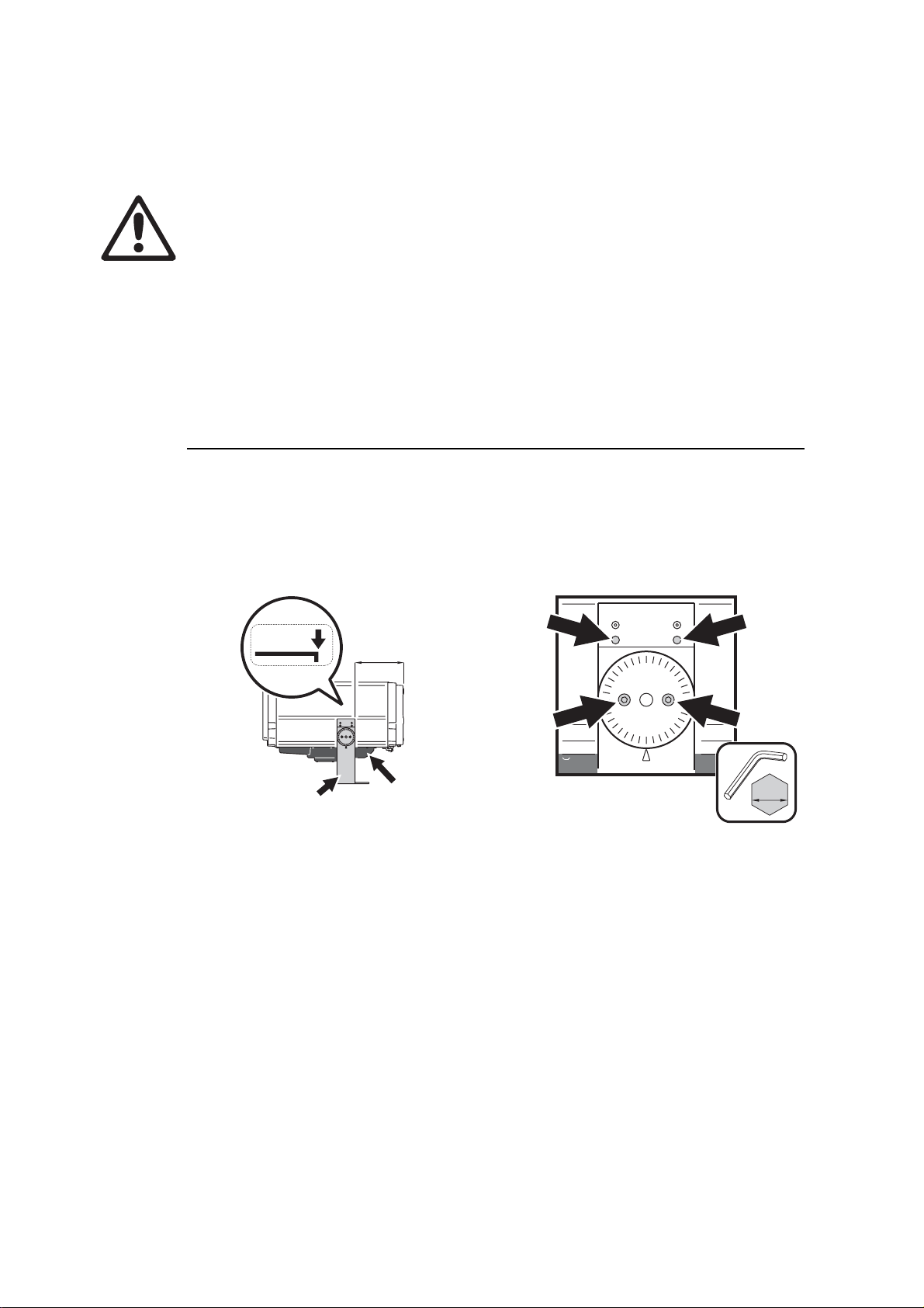
Figure 1: Mounting yoke adjustment
14 Exterior 1200 Wash user manual
See Figure 1. The mounting yoke is folded back for shipment. When the luminaire has
been unpacked:
1. Supporting the luminaire’s weight, rest it on its top (the opposite surface to the heat
exchanger) and use an Allen key to loosen the yoke clamp locking screws (A) and tilt
lock screws (B) on each side of the yoke.
2. Fold the yoke around to the bottom of the fixture (normally the side with the heat
exchanger), and slide the yoke forwards un til the edge of the yoke lines up with the
mark (arrowed) on the label on the side of the luminaire. In this position, the edge of
the yoke is 300 mm (12 in.) from the end of the luminaire and the lumina ire ’s weight is
balanced in the yoke.
3. Tighten the yoke cla mp locking screws and tilt lock screws to approximately 16 Nm
(11.8 ft.-lbs.).
3.1.2 Location and mounting
DANGER! Read "Safety information" on page 4 before attempting to install
this product.
Installation will probably be easiest if the lamp is installed before installing the luminaire
(see "8.5.3: Installing the lamp" on page 62).
Lifting
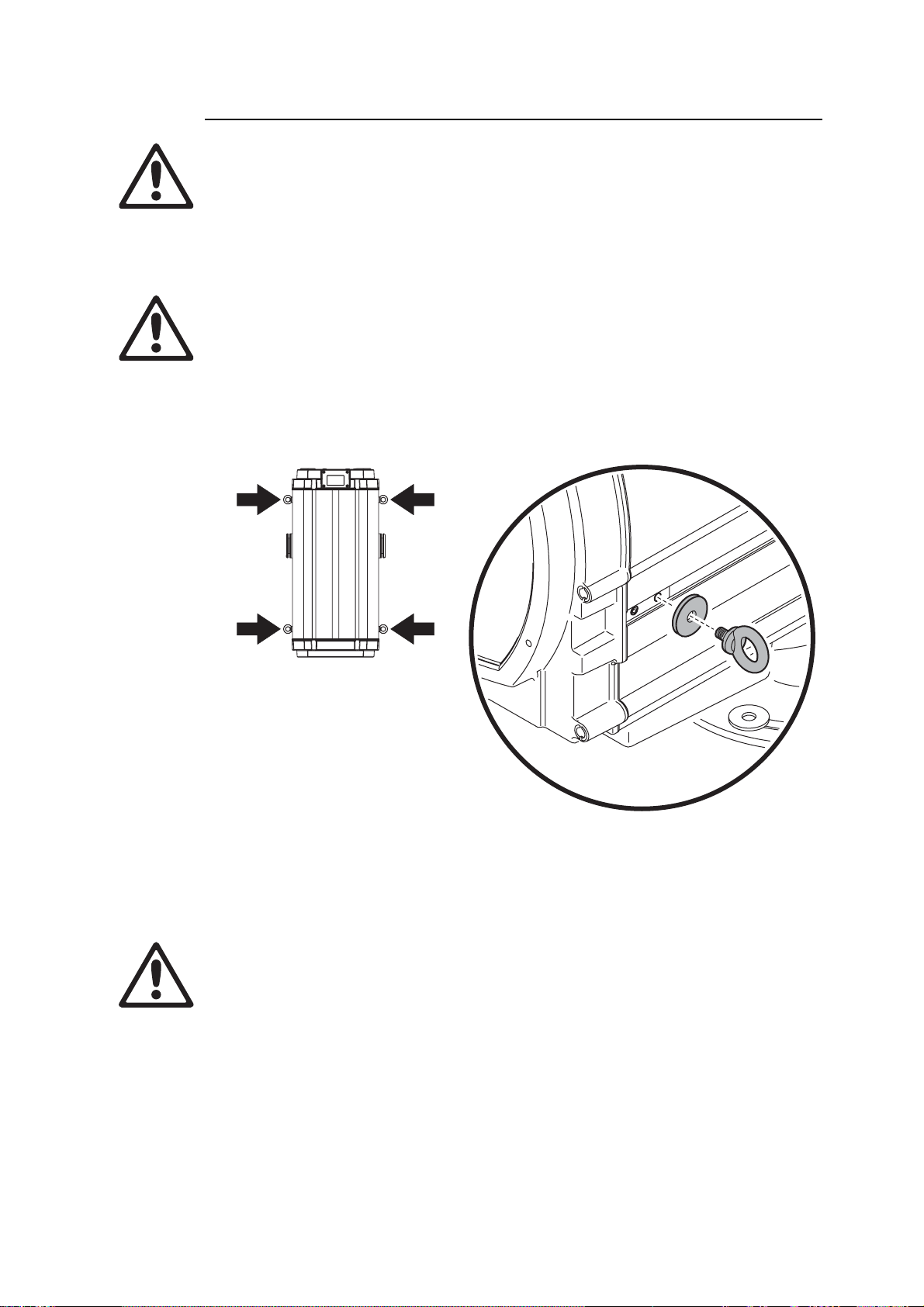
DANGER! Use only the lifting eyebolts provided to lift the luminaire.
Eyebolts must be securely installed with washers at all four corners of the
luminaire as illustrated below.
See Figure 2. The Exterior 1200 Wash is supplied with four eyebolts for lifting purposes
during installation or service. Do not use any other method to lift the luminaire. The
eyebolts screw into blocks in the yoke slider channels on each side of the fixture. Use the
supplied washers to avoid damage to the luminaire housing. Make sure that eyebolts are
firmly screwed in and will not slide in the channels before attempting to lift the luminaire.
Figure 2: Lifting eyebolts
Do not expose the eyebolts to undue stress while lifting, by allowing the luminaire to drop
and then catching it again, for example. Do not use the eyebolts for safety attachment.
Location and orientation
DANGER! The Exterior 1200 Wash mounting yoke base must be securely
anchored to a suitable flat surface. Ensure that the supporting structure can
bear the weight of all installed devices plus an adequate safety margin.
Consult a qualified engineer to determine a suitable anchoring method and to verify that
the structure can safely bear the luminaire’s weight.
Physical installation 15
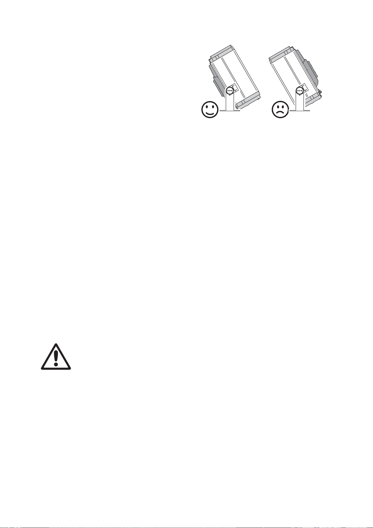
The Exterior 1200 Wash is rated UL Wet
Location. When choosing a location for
installation, consider that the main
housing has an ingress protection (IP)
rating of 65, but that the heat exchanger
unit must be protected from rain or direct
water projections that might fill the heat
exchanger with water and cause
overheating. The luminaire may
therefore be installed in any orientation,
but it must be positioned so that the heat
exchanger is on the lower side of the
luminaire (see Figure 3). If necessary,
loosen the yoke tilt lock screws (B in
Figure 1) and reposition the yoke.
Allow for service access to the front and rear of the luminaire.
The Exterior 1200 Wash can be installed outdoors but:
• Do not expose it to high-pressure water jets from any direction
• Do not immerse it in water (or any other fluid)
• Do not install it in a location where flooding may occur.
Ensure sufficient drainage to cope with the heaviest rainfall. Make sure that water can
drain away from the installation area at least as fast as it can enter it.
Heat exchanger position
Figure 3:
The Exterior 1200 Wash requires free and unobstructed airflow around the heat
exchanger to ensure adequate cooling:
• Do not bury the luminaire or otherwise locate it in an unventilated space
• Allow 135 mm (5.5 in.) free space around the heat exchanger
• Make sure that leaves, litter or other debris cannot be sucked into the heat exchanger,
as blockages may cause overheating and result in damage that is not covered by the
product warranty.
Install the luminaire at least 1 m (40 in.) away from the surface to be illuminated and any
combustible materials (wood, paper, etc.) and well away from any flammable materials.
The aluminum housing reaches temperatures up to 90° C (194° F). Restrict public access
or locate the luminaire so that it cannot accidentally be to uched.
Mounting fasteners
DANGER! All fasteners used to mount the Exterior 1200 Wash must be
corrosion-resistant and strong enough to mount the luminaire safely.
The mounting yoke allows the luminaire to be manually panned (i.e. rotated horizontally)
and tilted for beam aiming adjustment. The yoke base must be safely anchored to a
horizontal surface. The number and type of fasteners used will depend on the installation,
but use at least four high-strength corrosion-resistant fasteners (recommend ed minimum
properties: A4-70 grade according to ISO 3506 or grade 8.8 a ccording to accordin g to ISO
898-1) evenly distributed around the yoke base. Any nuts used must be self-locking. The
washers supplied with the luminaire must be installed between the head of each fastener
and the yoke base.
To mount the luminaire, evenly space 12 mm (1/2 inch) thread diameter bolts at 90°
intervals on a 123.5 mm (4.86 inch) radius from the center of the mounting location, so
16 Exterior 1200 Wash user manual
that one bolt passes through each curved slot in the yoke base (see Figure 4 ). If additional
13
432
110
Ø247
Power
230V AC
50 Hz
OPTO-
SPLITTER
DMX
Universe #2
OPTO-
SPLITTER
Power
230V AC
50 Hz
Power
230V AC
50 Hz
Max. 32 luminaires
or
500m. before
opto-splitter
is
required.
OPTO-
SPLITTER
DMX
Universe #1
DMX
Universe #2
bolts are required to mount the luminaire safely, pan adjustment range will be reduced.
Figure 4: Mounting yoke attachment points
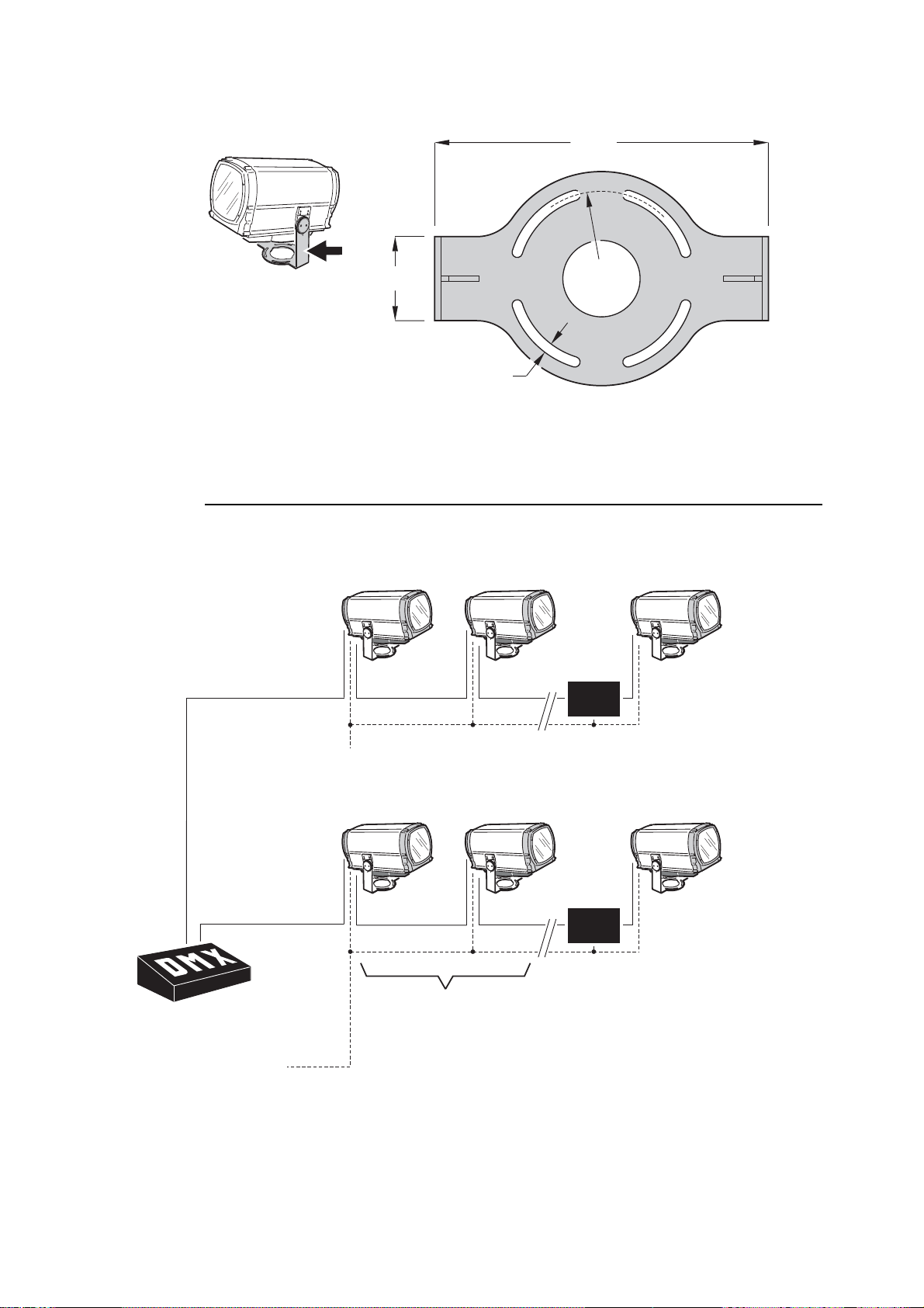
3.1.3 Power and DMX data cable layout
Figure 5 gives an overview of a suitable cable layout. The dotted lines represent AC
power circuits. The solid lines represent the data link.
Universe #2
AC power
50 Hz
Universe #1
AC power
50 Hz
Figure 5: Schematic cable layout diagram
Max. 32 luminaires
or 500m. before
opto-splitter
is required.
Physical installation 17
3.1.4 Connections compartment access
DANGER! Fuseholders remain live even if the MAINS switch is set to off. Cut
power to the luminaire before changing a fuse.
To gain access to the connections compartment:
1. If the luminaire has been in use, allow it to
cool completely.
2. If you intend to open a main fuseholder, cut
AC power to the luminaire and ensure that
power cannot be reapplied accidentally by
locking it out.
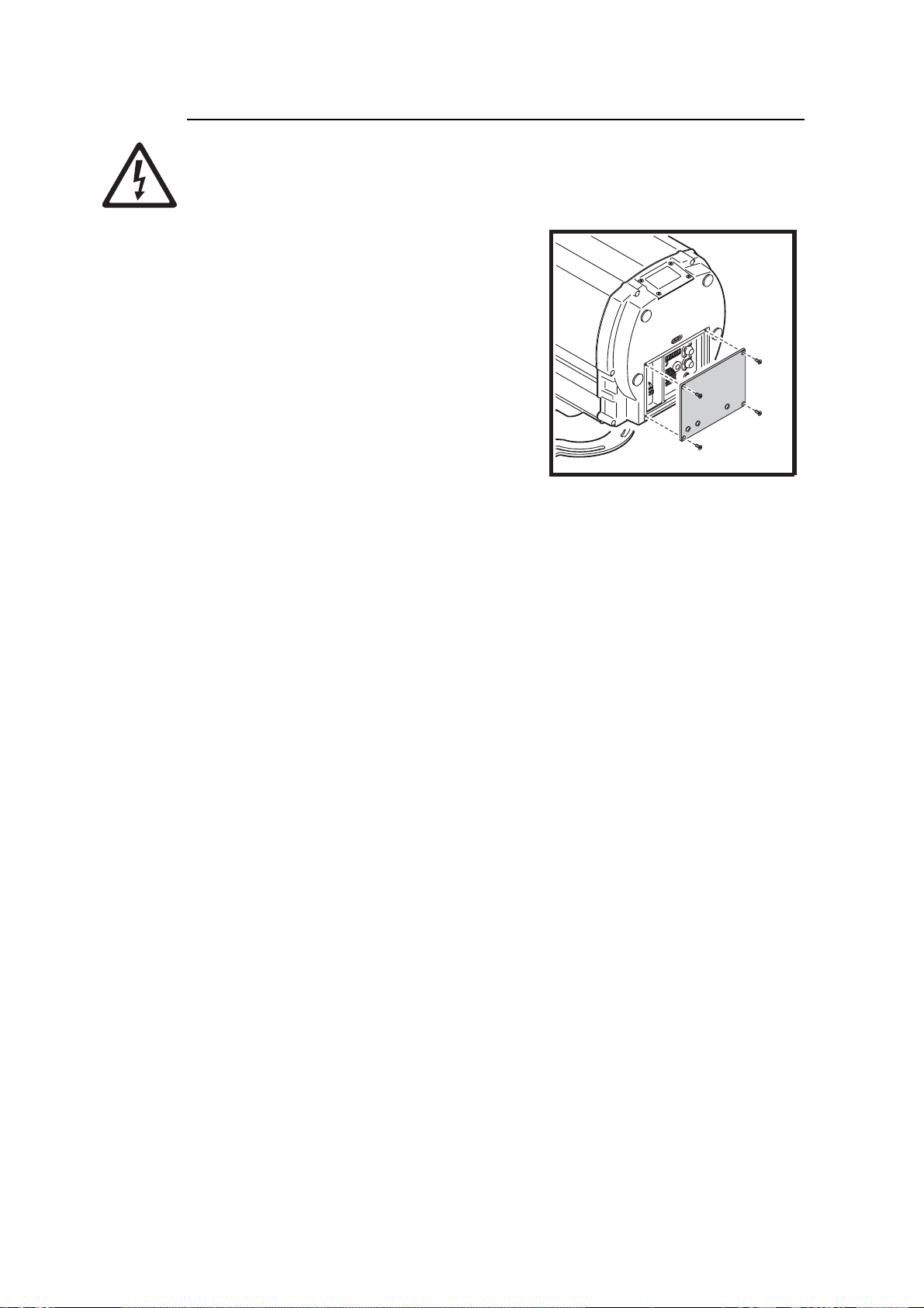
3. See Figure 6. Loosen the screws in the rear
cover plate and carefully remove the plate
and seal.
4. If you intend to alter any connections, shut
down AC power by setting the MAINS switch
to 0 (off). Before you touch any connectors,
use a tester to check that they are not live.
After access to the connections compartment:
1. Check the condition of the rear cover seal. Replace with a new item if the seal is torn,
cracked or brittle.
Figure 6: Connections
compartment cover plate
2. Hold the rear cover plate and seal firmly against the luminaire housing. Adjust the
sides of the seal so that the seal sticks out a little, just enough so that you can feel the
seal when you run a finger across the joint.
3. Cross-tighten the cover plate screws gradually and evenly to 2 Nm (1.5 ft.-lbs.). At this
torque, the seal will be compressed by about one-third and will be waterproof to IP65.
18 Exterior 1200 Wash user manual

3.2 Installing AC power
DANGER! Read "Safety information" on page 4 before attempting to install
this product.
Electrical installation must be carried out by qualified professionals only.
For protection from dangerous electric shock, the luminaire must be
grounded (earthed). The AC power distribution system must be fitted with
current overload and ground-fault (earth-fault) circuit breakers as well as a
means to isolate luminaires from power and lock out power during service.
Important! Do not connect the Exterior 1200 Wash to an electrical dimmer
system. Doing so can damage the electronics.
See Figure 5 on page 17 for a schematic diagram of cable layout.
If there is a break or cut at any point in a cable (for example at a conn ec tio n po int ), an d if
this is exposed to water, moisture can be drawn up the inside of the cable due to the
vacuum effect of temperature fluctuations during operation. Ensure that the luminaire is
protected from the entry of water via the power cable by using IP65-rated connectors or
junction boxes, or by protecting connectors with weatherproof housings.
The Exterior 1200 Wash must be supplied with power via an electrical cable that is
adequately dimensioned for the current requirements and suitable for the installation
environment, particularly with regard to water, pollution, thermal and UV resistance. Use
Hypalon or neoprene rubber-jacke t cable r ated to 90° C ( 194° F) min imum. The conductor
size must be 1.5 mm
condition.
2
(16 AWG) minimum. Check that all power cables are in perfect
See "Exterior 1200 Wash specifications" on page 78 for details of fuse rating and typical
current. If you require help in planning or dimensioning the power distribution system,
please contact your Martin Architectural supplier for assistance.
Electrical power installation consists of two steps:
1. Configuring for local AC power
2. Connecting to AC power.
3.2.1 Configuring for local AC power
Before AC power is applied to the Exterior 1200 W ash for th e first time (or if the AC powe r
voltage or frequency changes), the lu minaire must be configured to a ccept the local power
voltage and frequency as described in this section.
The Exterior 1200 Wash can accept the following AC voltages and frequencies:
• 200 V, 208 V, 220 V, 230 V, 240 V, 250 V or 277 V at 50 or 60 Hz.
Operating at the incorrect power setting can result in overheating and damage to the
luminaire and lamp. If your local power voltage differs from the voltage settings listed here
and in the luminaire, contact your Martin Architectural supplier for assistance.
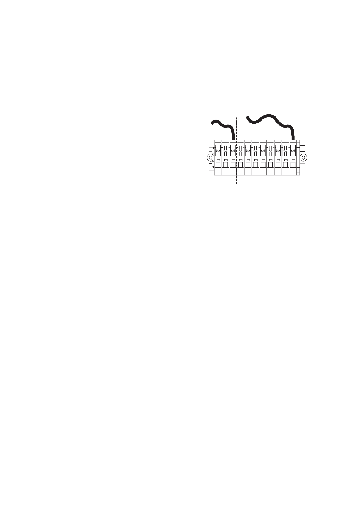
The luminaire must be configured to accept the local AC power frequency and voltage by
connecting the free ends of two jumper leads. The fixed end of each lead sit s in an orange
terminal. The free end of each lead must be connected to the appropriate terminal on the
terminal block. Terminals are labelled.
Installing AC power 19
The terminals are spring-loaded, and leads can be released by exerting light pressure on
50
60
277
250
240
230
220
208
200
the terminal tab with a flat-head screwdriver.
To configure the luminaire for local AC power:
1. Make sure that the luminaire is isolated from AC power and cannot be accidentally
connected throughout the procedure.
2. Open the connections compartment as described in "3.1.4: Connections comp artment
access" on page 18.
3. See Figure 7. Connect the free end of the
frequency setting jumper lead (in the
section marked Hz setting) to the
terminal labeled with the local AC power
frequency.
4. Connect the free end of the voltage
setting jumper lead (in the section marked
Volt setting) to the terminal labeled with
the local AC power voltage.
Hz setting Volt setting
Figure 7: Frequency and v oltage
settings
3.2.2 Connecting to AC power
Power cable must enter the luminaire through an M20 x 1.5 cable gland that accepts 8 13 mm (0.32 - 0.5 in.) external diameter cables. A gland is supplied with the luminaire.
The cable gland must be replaced if the power cable diameter is not within this range (see
"8.4.2: Cable glands" on page 59).
One of two cable entry points can be used: either on the cover plate at the rear of the
luminaire, or through the bottom of the connections/power compartment. Using the bottom
of the connections/power compartment is recommended, as cables installed here will not
be disturbed or flexed when the rear cover plate is removed for service. All cable entry/exit
holes that are not used must be sealed with blanking plugs.
1. Make sure that the power cable is isolated from powe r an d th at powe r ca nn ot be
applied accidentally. If the luminaire has been in use, allow it to cool for at least 20
minutes.
2. If necessary, remove the rear cover plate as described in "3.1.4: Connections
compartment access" on page 18
3. Check that the jumper leads are correctly connected to match the local AC power
voltage and frequency (see "3.2.1: Configuring for local AC power" on page 19).
20 Exterior 1200 Wash user manual
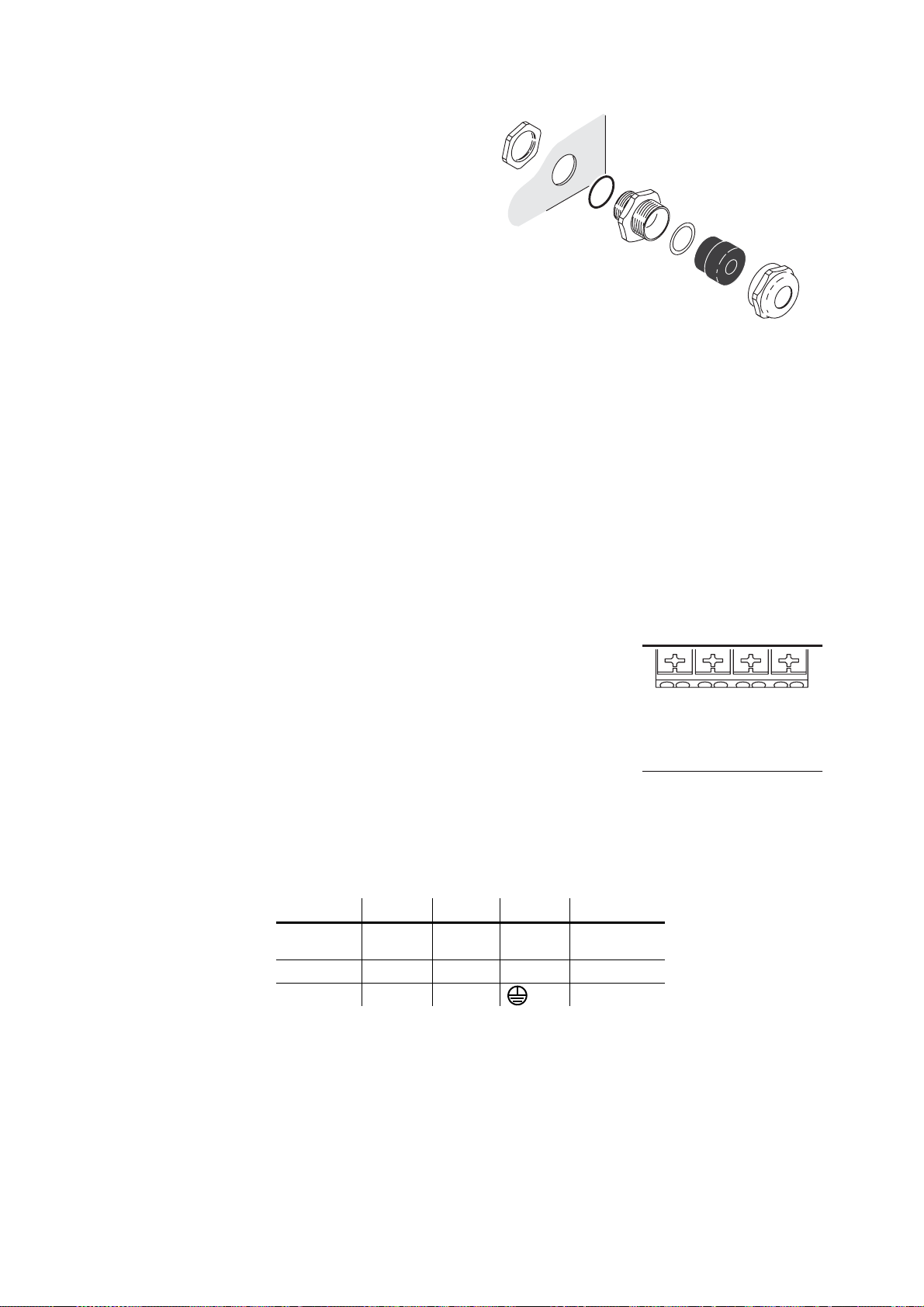
4. See Figure 8. Ensure that there is
50
60
277
250
240
230
220
208
200
Ground
Neutral
Live
1
Live
2
MAINS
MAIN
FUSE
PCB
Live 2
Fuse
Live 1
Fuse
a rubber seal B on the locking nut
end of the cable gland C, and
push this end through the hole
provided in the housing so that
the seal faces the outer surface
of the housing.
5. Screw the locking nut A onto the
cable entry from inside the
housing. Prevent the cable entry
from turning, and tighten the
locking nut until the seal makes a
water-resistant seal against the
outer surface of the housing. Do
not over-tighten, as this may
damage the seal or housing.
A
B
C
D
E
F
A – Locking nut
B – Seal
C – Cable entry
D – Washer
E – Gland
F – Compression nut
6. Thread the cable through the
Figure 8: Cable gland assembly
compression nut F, gland E,
washer D, and cable entry C into
the housing.
7. Allow enough cable slack inside the housing to make connections. Prevent the cable
entry from turning and tighten the compression nut sufficiently to make a waterresistant seal. Do not over-tighten, as this may damage the gland. Check that the
cable is firmly gripped in the rubber gland.
8. See Figure 9. The power terminals block has three
terminals labelled Ground, Neutral, Live 1 and Live 2.
Connect the power cable as follows:
• Connect the power cable’s ground (earth) wire to the
terminal marked Ground.
• If using a single-phase system, connect the power
Live 1
Live 2
cable’s neutral wire to the terminal marked Neutral and
connect the power cable’s live wire to the terminal
marked Live 1.
• If using two 120 V phases of a three-phase system to
obtain 208 V, connect one phase to Live 1 and the next
phase to Live 2.
Figure 9: Power
terminals
Some common wire color codes are listed in Table 2:
Wire (EU) Wire (US) Pin Marking Screw (US)
brown black live “L”
blue white neutral “N” silver
yellow/green green ground green
Table 2: Common wire color codes
yellow or
brass
9. If you are also connecting data cables, connect these now, referring to the next section
in this manual. Otherwise replace the rear cover plate as described in "3.1.4:
Connections compartment access" on page 18.
Installing AC power 21

3.3 Installing a data link
Exterior 1200 Wa sh lumina ires must be conn ecte d via a serial dat a l ink for DMX contro ller
operation and for synchronized stand-alone op eration of multiple luminaires. The dat a link
is used to transmit DMX commands or synchronization data.
See Figure 5 on page 17 for a schematic diagram of cable layout.
3.3.1 Planning the data link
The following considerations must be taken into account when planning the data link:
• RS-485 data cable designed for exterior use is required. RS-485 cable has low
capacitance and a characteristic impedance of 85 to 150 Ohms. It is electrica lly shielded
and has at least 1 twisted pair of conductors. The minimum recommended wire size is
0.25 mm
runs up 500 meters (1640 ft).
• The maximum permitted control data cable length before a control signal amplifier is
required is 500 meters (1640 ft.).
• Luminaires must be ‘daisy-chained’, i.e. the data cable must be connected in one single
chain of luminaires.
• Each daisy-chained link may connect a maximum of 32 fixtures.
• An optically isolated amplifier-splitter such as the Martin RS-485 Opto-Splitter (P/N
90758060) must be used to:
- extend a link beyond 500 meters (1640 ft.)
- extend the link to include a further maximum 32 luminaires, or
- branch the link into further single chains, each containing 32 luminaires. The Martin
• The last device on each chain must be terminated inside the luminaire using a 120 Ohm,
0.25 Watt resistor (available from your Martin Architectural supplier: P/N 04150308)
connected across the hot and cold data terminals.
• Long parallel runs of AC power and control data cables may cause interference on the
data link and must be avoided. Even if not required by law, separate conduits are
recommended for power and data cables.
• One DMX universe has 512 DMX control channels available. In an installation cont aining
multiple luminaires that each use 8 DMX channels, for example, one DMX universe will
be required for every 64 luminaires (512 ÷ 8 = 64).
2
(24 AWG) for runs up to 300 meters (1000 ft.) and 0.32 mm2 (22 AWG) for
Opto-Splitter allows a link to be branched into four new chains.
3.3.2 Building the data link
Data cable must enter and exit the luminaire through M16 x 1.5 cable glands that accept
5.5 - 10 mm (0.22 - 0.39 in.) diameter cables. Two glands are supplied with the luminaire.
The glands must be replaced if the data cable external diameter is not within this range
(see "8.4.2: Cable glands" on page 59).
One of two cable entry points can be used: either on the cover plate at the rear of the
luminaire, or through the bottom of the connections/power compartment. Using the bottom
of the connections/power compartment is recommended, as cables installed here will not
be disturbed or flexed when the rear cover plate is removed for service. All cable entry/exit
holes that are not used must be sealed with blanking plugs.
22 Exterior 1200 Wash user manual
Connection pinouts
XLR connection
XLR connectors are suitable if DMX cable is used for the data link.
XLR pin numbers are normally marked on connectors. Connectors must be wired using
the standard XLR DMX pin-out:
• Pin 1: Cable shield
• Pin 2: DMX Data 1 - (cold)
• Pin 3: DMX Data 1 + (hot)
Pins 4 and 5 on 5-pin XLR connectors are available for Data 2 connections in DMX 512-A
or similar systems. They must be wired as follows:
• Pin 4: DMX Data 2 - (cold)
• Pin 5: DMX Data 2 + (hot)
To avoid ground/earth loop interference, ensure that the DMX cable shield does not come
into contact with the shell or body of XLR connectors.
RJ-45 connection
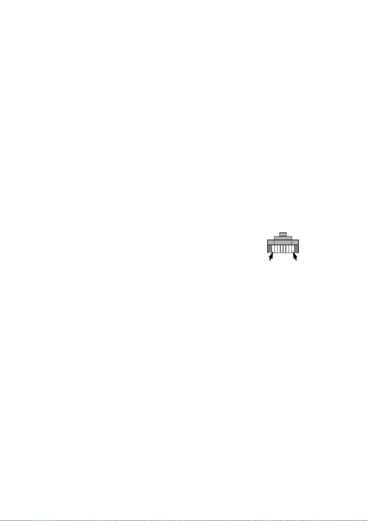
RJ-45 connectors are suitable if CAT 5 cable is used for the data link.
RJ-45 cable connector pins are numbered from the left looking at the face of the
connector with the locking clip on top (see Figure 10). Connectors must be wired using the
standard RJ-45 DMX pin-out:
• Pin 1 (WHITE/orange): DMX hot (+)
• Pin 2 (ORANGE/white): DMX cold (-)
• Pins 7 (WHITE/brown) and 8 (BROWN/white):
Common
Pins 3 and 6 are available for Data 2 connections in
DMX 512-A or similar systems. They must be wired as
follows:
• Pin 3 (WHITE/green): Available for Data 2 ho t (+)
• Pin 6 (GREEN/white): Available for Data 2 cold (-)
Pin 1 Pin 8
Figure 10: RJ-45 cable
connector pins
Pins 4 and 5 are not used in currently available ligh tin g con tr ol sys te ms but can be wire d
as follows:
• Pin 4 (BLUE/white): Not used
• Pin 5 (WHITE/blue): Not used
Connecting the link
To build a data link:
1. If the luminaire has been in use, allow it to cool for at least 20 minutes.
2. Connect the data cable to a DMX output socket on the DMX controller and route it to
the first luminaire on the link.
3. If the rear cover plate is not already open, remove it as described in "3.1.4:
Connections compartment access" on page 18
4. Pass the data cable into the luminaire using one of the supplied cable gland s to ensure
waterproof cable entry. See page 21 for details of installing the cable gland.
Installing a data link 23
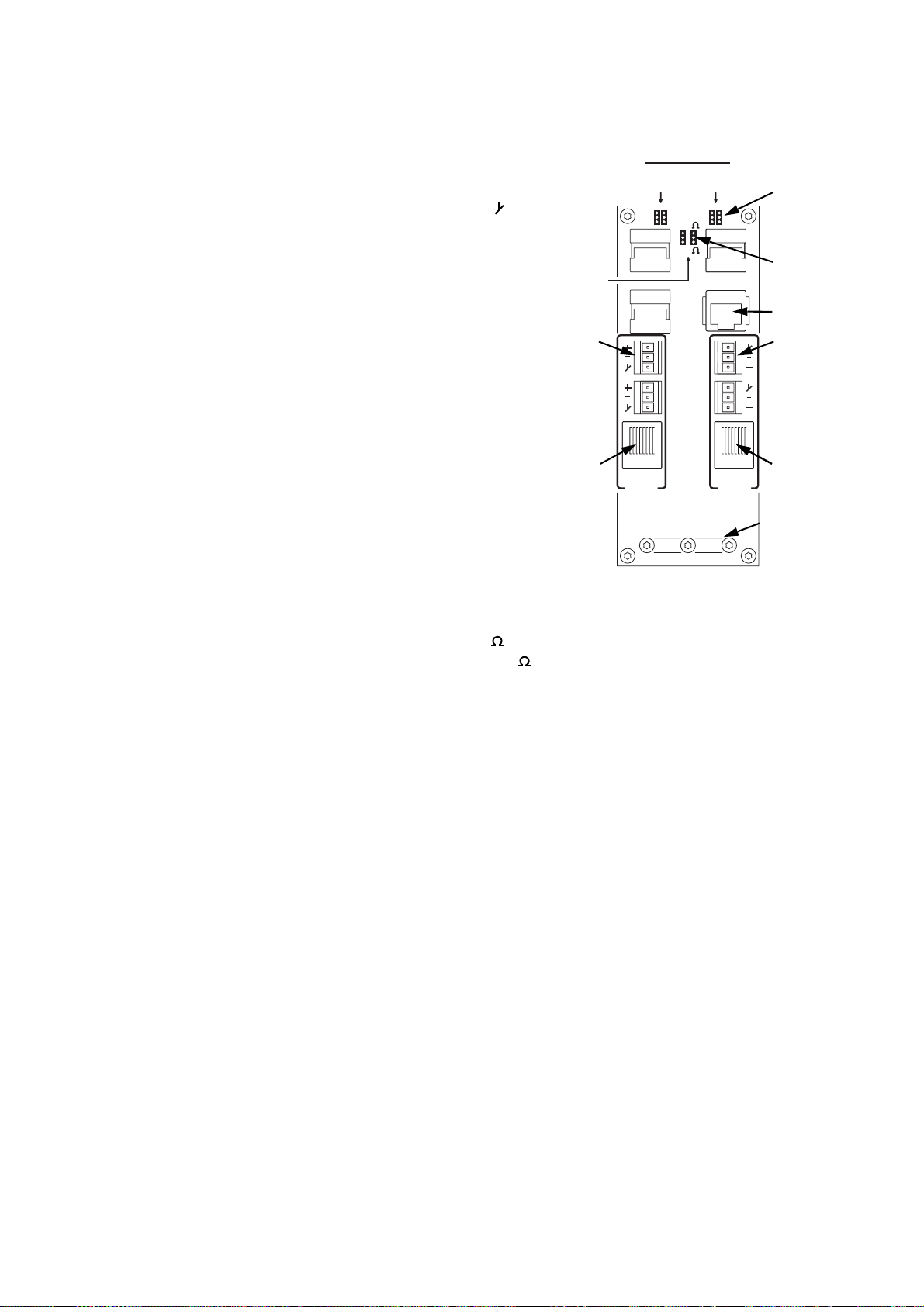
5. Data cable can be connected either via screw terminals on removable connectors or
Data
2
Data
1
Termination
Data
set 2
Data
set 1
50
60
277
250
240
230
220
208
200
DMX
OUT
MAINS
MAIN
FUSE
PCB
zHz Setting Volt Setting
Live 2
Fuse
Live 1
Fuse
Ground
Neutral
Live 1
Live 2
50
60
277
250
240
230
220
208
200
Hz Setting Volt Setting
Service
RJ45
DMX
IN
Cable
impedance
100
120
Data
2
Data
1
Termination
Data
set 2
Data
set 1
50
60
277
250
240
230
220
208
200
DMX
OUT
MAINS
MAIN
FUSE
PCB
zHz Setting Volt Setting
Live 2
Fuse
Live 1
Fuse
Ground
Neutral
Live 1
Live 2
50
60
277
250
240
230
220
208
200
Hz Setting Volt Setting
Service
RJ45
DMX
IN
Cable
impedance
100
120
via RJ-45 connectors.
See Figure 11. Either connect the data cable
to the luminaire’s Data 1 DMX IN screw
terminals (A) as follows:
Termination
Termination
set 2
set 2
set 1
set 1
- Connect shield to the terminal marked
- Connect cold (-) to the terminal marked -
- Connect hot (+) to the terminal marked +
or install an RJ-45 connector on the data
cable respecting the pinout listed under "RJ-
45 connection" on page 23 and insert the
connector into the DMX IN RJ-45 socket (B).
E
6. Depending on whether the luminaire is the
last one on the link or whether the data link
needs to be continued to another luminaire,
follow one of the following two procedures:
• If the luminaire is the last one on a branch
of the data link, use a pair of long-nosed
F
pliers to move the DMX termination
jumpers from the Data set 1 pins (C)
marked OFF to the pins marked ON. This
places a resistance across data hot and
cold to terminate the data link. Ensure that
the termination resistance matches the
type of cable used by setting the Cable
Figure 11: DMX
connections
impedance jumpers (D) to either 100 if
using CAT5 cable for the data link, or 120 if using standard DMX cable.
• If you need to continue the data link to another luminaire, leave the termination
jumpers at OFF. Pass the data output cable into the luminaire using another cable
gland as described above. Connect to the luminaire’s Data 1 DMX OUT terminals
(E) or RJ-45 DMX OUT socket (F), respecting the same pinouts as for the dat a input
cable.
7. If using shielded CAT5 cable, connect the cable shield to PCB ground (earth) by
routing the cable under the clamp (G), folding back the cable shield and tightening the
clamp so that it makes good contact with the shield. .
G
C
D
G
B
B
A
H
H
8. If the power cable has not already been connected, you can connect it now (see
"3.2.2: Connecting to AC power" on page 20). Otherwise reinstall the rear cover plate
as described in "3.1.4: Connections compartment access" on page 18.
9. Route the data output cable to the data input of the next luminaire, and continue
Add an optically isolated amplifier/splitter into the link if you intend to add more than 32
connecting up to a total of 32 luminaires, output to input, as described above.
luminaires or branch the link.
The Data 2 connections are reserved for future use.
24 Exterior 1200 Wash user manual

Section 4. General
Installing a data link 25

4.1 General
DANGER! Read "Safety information" on page 4 before applying power to the
Exterior 1200 Wash.
This section contains general information about the features and functions as well as
basic programming and operating principles of the Exterior 1200 Wash. Read this section
to familiarize yourself with the luminaire before attempting to program or operate it.
4.1.1 Powering on
Important! Leave the luminaire powered on permanently except during service.
When the luminaire is connected to power for the first time, it will start running a factoryset light show to test the fixture. It will continue to run this test show until a new show is
programmed into it, or until it receives DMX commands.
When the luminaire is powered on in normal use, the luminaire software version appears
in its display, runs an internal test and resets all effects to start positions. It must complete
this reset before it can respond to DMX commands or run a stand-alone show.
Except during service, maintain power to the luminaire permanently, even when the lamp
is not lit. This will allow cooling fans to regulate the luminaire’s internal temperature if the
sun’s rays are strong enough to cause excessive heating. Heat damage resulting from
failure to maintain power is not covered by the product warranty.
4.1.2 Powering off
Important! Switch off the lamp 8 minutes before you cut power to the luminaire.
If the lamp is lit and you wish to cut power (for service, for example), you must first switch
off the lamp via DMX or the onboard control panel and wait at least 8 minutes before you
cut power. This will give cooling fans enough time to reduce the luminaire’s temperature
and avoid heat damage. Damage caused by failure to follow this procedure is not covered
by the product warranty.
4.1.3 Lamp operation
After being switched off, the lamp must cool for at least 8 minute s before it can be
switched back on. “Lamp On” commands sent within 8 minutes of a “Lamp Off” command
are stored and then attempted again after the time has elapsed.
The lamp can be set to start automatically as soon as power is applied to the luminaire or
started via DMX.
Discharge lamps draw an extra inrush current for a fractio n of a seco nd during st artup . If a
large number of luminaires start up at the same time, this current can trip circuit breakers.
Therefore:
• If the lamp is set to start automatically when power is applied, it starts af ter a random
delay of 0 - 90 seconds.
26 Exterior 1200 Wash user manual
 Loading...