

Page 1
®
MARTIN
DT2S Secondary
Cleaner
Installation Instructions
M3687UK
Page 2

© Martin Engineering GmbH M3687UK-12/17
Page 3

1Table of Contents
1 Table of Contents ............................................................. 1
2 Introduction ...................................................................... 3
2.1 About these installation instructions................................... 3
2.1.1 Scope ............................................................................ 3
2.1.2 Copyright ....................................................................... 3
2.1.3 Exclusion of liability ....................................................... 3
2.1.4 Reference to additional documents ............................... 4
2.1.5 Classification of the hazards.......................................... 5
2.2 Intended usage.............................................................. 6
2.2.1 Conveyor systems with open transfer systems ............. 6
2.2.2 Usage in explosion-protected areas .............................. 6
2.2.3 Restrictions on the use of the product........................... 7
2.3 Occupational safety............................................................ 7
2.3.1 Safety information, occupational safety ......................... 7
2.3.2 Duties of the owner-operator......................................... 8
2.3.3 Authorised personnel ..................................................... 8
3 Description of the product .............................................. 9
3.1 Design and function ........................................................... 9
3.2 Type designation ......................................................... 10
4 Preparing for the installation ........................................ 11
4.1 Before the installation....................................................... 11
4.1.1 Required materials and tools ....................................... 11
4.1.2 Preparatory measures ................................................. 11
5 Installation ...................................................................... 13
5.1 Safety information ............................................................ 13
5.2 Installation process...................................................... 14
5.2.1 Determination of the installation position ..................... 15
5.2.2 Conversion of the Bottom Mount spring tensioner
to Top Mount ............................................................... 18
5.2.3 Replacing springs ........................................................ 23
5.2.4 Installing the tensioner................................................. 24
5.2.5 Installing the cleaner.................................................... 25
5.2.6 Securing the cleaner .................................................... 26
5.2.7 Centring the secondary cleaner beneath
the conveyor belt ......................................................... 27
5.2.8 Aligning the secondary cleaner in parallel
to the driving drum axis ............................................... 28
5.2.9 Aligning the secondary cleaner horizontally
to the driving drum axis ............................................... 29
5.2.10 Tightening the cleaner................................................. 30
5.3 Operation with loading................................................. 36
5.4 Placement of warning labels and warning tags ........... 38
6 Maintenance ................................................................... 39
6.1 Safety information ............................................................ 39
6.2 Weekly maintenance........................................................ 39
6.3 Replacing the blades................................................... 42
Table of Contents
© Martin Engineering GmbH 1 M3687UK-12/17
Page 4

7 Troubleshooting ..............................................................49
7.1 Safety information............................................................. 49
7.2 Troubleshooting ................................................................ 49
8 Storage, De-installation, Disposal .................................51
8.1 Packing and transportation ............................................... 51
8.2 Storage ............................................................................. 51
8.3 De-installation ................................................................... 51
8.4 Disposal ............................................................................ 51
9 Part numbers ...................................................................52
9.1 Explanation of part numbers............................................. 52
9.2 Martin
Table of Contents
9.3 Accessories....................................................................... 54
9.4 Warning labels / Warning tags.......................................... 54
9.5 MARTIN
9.6 MARTIN
9.7 MARTIN
9.8 MARTIN
10 Declaration of Incorporation ..........................................64
®
Inspection Doors.............................................. 54
®
DT2S Secondary cleaner............................. 55
®
DT2SC Secondary cleaner cartridge........... 58
®
DT2S Spring tensioner ................................ 60
®
DT2S Air tensioner ...................................... 62
© Martin Engineering GmbH 2 M3687UK-12/17
Page 5

2 Introduction
2.1 About these installation instructions
Non-compliance with these installation instructions can result in loss
of compensation for damage and/or warranty claims.
2.1.1 Scope
These installation instructions apply solely for the product described
herein and are intended for those persons who install this product,
commission it and monitor its usage.
2.1.2 Copyright
The products described and these installation instructions are
protected by copyright. Any reproduction without a licence will be
prosecuted. All rights to the present document are reserved,
including its reproduction and/or copying in any conceivable
manner. Reprints of this document require the written consent of
Martin Engineering.
Introduction
The technical standard at the time of delivery of the product and its
technical documentation are decisive as long as no other
information is provided. The product and documentation may be
subject to technical changes without prior notification. Earlier
documents then lose their validity. Martin Engineering's General
Terms of Sales and Delivery shall apply.
2.1.3 Exclusion of liability
Martin Engineering guarantees the flawless function of its product in
accordance with its advertising, the published product information
and its technical documentation. Martin Engineering shall assume
no liability for efficiency and flawless function if the product is used
for a purpose other than that described in the “Intended Use” section
or for damage resulting from the use of accessories and/or spare
parts which were not supplied and/or certified by Martin
Engineering.
© Martin Engineering GmbH 3 M3687UK-12/17
Page 6

Introduction
2.1.4 Reference to additional documents
Martin Engineering products are designed for a long service life.
They conform to the state of the art in science and technology and
were thoroughly inspected before shipment. In addition to this,
Martin Engineering constantly performs product and market
research for continuous product development.
Martin Engineering offers competent support whenever
malfunctions and/or technical problems occur. Suitable actions are
taken immediately. The warranty provisions of Martin Engineering
apply and can be sent to you as needed.
Reference is made in these installation instructions to the following
documents:
• Installation instructions for the MARTIN
Publication no. M3127.
The following standards and directives were complied with in the
preparation of these installation instructions:
• EU Machinery Directive (2007/42/EC)
• ISO/IEC Guide 37 “Installation instructions for products
used by consumers”, 1995 Edition
• DIN 1421 “Arrangement and numbering in texts”,
Edition 1983-01
• DIN/EN 12100 “Machine safety - basic definitions,
general design guidelines”, Edition 2010-11
• DIN/ISO 16016 “Technical product documentation Protection notices for restricting the use of documents and
products“, Edition 2007-12
• DIN/EN 60204-1 “Safety of machines - Electrical
Equipment of Machines, Part 1 General requirements”,
Edition 2007-07
• DIN EN 82079-1 - Creation of user manuals - Structuring,
content and presentation, Part 1 General principles and
detailed requirements.
®
Inspection door,
© Martin Engineering GmbH 4 M3687UK-12/17
Page 7
2.1.5 Classification of the hazards
DANGER
Represents an immediately threatening danger which leads to
serious bodily injuries or death if not avoided.
WARNING
Represents a possibly hazardous situation which could lead to
serious bodily injuries or death if not avoided.
CAUTION
Represents a possibly hazardous situation which could lead to
minor bodily injuries and/or property damage if not avoided.
Introduction
NOTE
Contains comments about the installation and/or the product's
usage to point out situations which cause neither personal injury
nor property damage but include important information.
© Martin Engineering GmbH 5 M3687UK-12/17
Page 8

2.2 Intended usage
Introduction
2.2.1 Conveyor systems with open transfer systems
MARTIN® DT2S secondary cleaners are used to clean materials
clinging to conveyor belts. They can be used on conveyors with a
belt width of up to 2400 mm and a belt speed of up to 3.6 m/s. The
installation position of the cleaner directly downstream of the head
pulley ensures that the cleaned off material is fed back to the
material flow.
Every other usage of this product is deemed as misuse. Please
contact Martin Engineering customer service if you would like to use
this product for a different purpose. We will be happy to assist you
with the product configuration.
These installation instructions describe the installation on conveyor
systems with encapsulated transfer systems. Various MARTIN
installation brackets can be used on open transfer systems.
Martin Engineering or one of its representatives can assist with the
position or with special solutions in cases where the installation
conditions are complicated such as insurmountable static
components or a head pulley as the tensioning station.
2.2.2 Usage in explosion-protected areas
This product can also be used in potentially explosive areas under
certain conditions. Contact Martin Engineering for more information
on usage in potentially explosive areas.
The cleaner must not be used in a higher equipment protection
category or under other operating conditions than those specified by
Martin Engineering unless such usage has been approved by Martin
Engineering.
®
© Martin Engineering GmbH 6 M3687UK-12/17
Page 9

2.2.3 Restrictions on the use of the product
The product specified here may only be used within the scope of the
specifications referred to above. Usage in a higher equipment
protection category or under other operating conditions than those
specified by Martin Engineering shall be deemed misuse and is only
permitted if approved by Martin Engineering.
Operation of this product is only permitted if all parts are in a flawless
state. In case of damage (cracks, rust, etc...) changes or other
mechanical modifications, shut down this product immediately.
Martin Engineering or one of its representatives can assist you with
the product configuration if you need to use this product for a
different purpose.
2.3 Occupational safety
2.3.1 Safety information, occupational safety
These installation instructions must be read through in their entirety
before work may be started on the product or on the conveyor
system supplied by the customer.
Introduction
The owner-operator must ensure that all installation, inspection and
maintenance work is performed solely by trained specialists.
Work on conveyor systems and their accessories must always be
performed during shut-down. The procedures described in the
applicable installation instructions for shutting down the conveyor
system must always be complied with.
All of the safety devices and safeguards must be reattached and/or
made operational again immediately following completion of the
work.
The installation must be completed before the system is started up.
The flawless execution of all operating steps must be tested before
the conveyor system can be started up again. Please observe all
information on the installation and start-up of the product.
© Martin Engineering GmbH 7 M3687UK-12/17
Page 10

2.3.2 Duties of the owner-operator
Introduction
2.3.3 Authorised personnel
This product's owner-operator must ensure that this product is
installed, serviced and used solely by those persons who
• know the rules regarding occupational safety and accident
prevention,
• were trained on using this product and have read and
understood these installation instructions.
Personnel are considered authorised when they have suitable
training and technical experience, can demonstrate knowledge of
the applicable standards and directives, and are able to evaluate
tasks in order to recognise critical situations at an early stage.
Operating, maintenance and installation personnel
Personnel are considered authorised when they have been trained
on using the product and have read and understood these operating
instructions in their entirety.
© Martin Engineering GmbH 8 M3687UK-12/17
Page 11

3 Description of the product
3.1 Design and function
The Martin® DT2S secondary cleaner is primarily installed in
a cleaner system consisting of pre-cleaners and secondary
cleaners, but can also be used as a single cleaner.
The cleaner is installed directly behind a head pulley or tension
pulley. Its slide-on blade holder enables quick and easy
maintenance.
When the blades are properly selected, it can also be used on
reversing conveyor belts or conveyor belts with a high return flow
rate - also refer to the type description.
The cleaner can also be used in connection with mechanical joints
if they are in good condition and optimally installed.
Although pre-cleaners and secondary cleaners can each be used
individually, the installation of a system consisting of pre-cleaners
and secondary cleaners is recommended for an optimal cleaning
result.
Description of the product
NOTE
An unfavourably or improperly installed product can disrupt the
conveyor process or contaminate the bulk material to be
transported.
The owner-operator is responsible for taking the required
countermeasures.
In the case of applications with contaminants, Martin Engineering
or one of its representatives can assist with the positioning or with
special solutions.
© Martin Engineering GmbH 9 M3687UK-12/17
Page 12

3.2 Type designation
The Martin® DT2S secondary cleaners can be equipped with various
blade types:
• Reversing blades with tungsten carbide inserts
Also available completely of urethane or stainless steel for
reversing operation or conveyor belts with a high return
flow rate.
The Martin
different types of tensioners:
Description of the product
®
DT2S secondary cleaners can be equipped with two
• Spring tensioner
Can be used for most applications
• Air tensioner
For applications in heavily polluted areas or where air is
generally available. An additional advantage is that the
cleaner can be tensioned and slackened automatically.
© Martin Engineering GmbH 10 M3687UK-12/17
Page 13

4 Preparing for the installation
4.1 Before the installation
4.1.1 Required materials and tools
Along with the standard tools, the following special equipment may
be needed for the installation and maintenance of your product.
• Lifting device with a capacity greater than the weight of the
product (see delivery note for weight data).
4.1.2 Preparatory measures
NOTE
Perform the inspections described - carefully and completely.
The shipping company is liable for any transport damage!
Please contact the shipper with any damage claims.
Preparing for the installation
1. Inspect the delivery for the following conditions:
• Is the delivery complete? Does the number of pallets/
crates/containers delivered match the number on the
delivery note?
• Do all of the transport packages appear to be undamaged?
Does damage to the packaging indicate possible damage
to the product contained inside?
© Martin Engineering GmbH 11 M3687UK-12/17
Page 14

2. Always record any incompleteness or transport damage
discovered in the delivery and have it confirmed by the shipper.
All damaged products must be kept for inspection.
3. The delivery should include the following parts, depending on
the scope of the order:
•MARTIN
blades).
• Two Conveyor Products Warning Labels,
Part No. 23395
• Two Crushing Hazard Warning Labels Part No. 30528
4. Report any missing or damaged parts to Martin Engineering or
one of its authorised dealers.
®
DT2S secondary cleaner (mainframe, tensioner,
Preparing for the installation
© Martin Engineering GmbH 12 M3687UK-12/17
Page 15
5 Installation
5.1 Safety information
WARNING RISK OF INJURY!
Body parts and/or clothing may get caught and pulled in by
rotating parts or by the moving conveyor belt.
Before any installation or maintenance work is carried out, ensure
that all power sources to the conveyor belt system and its
accessories are switched off and secured against unauthorised
reactivation. Use warning s igns!
WARNING DANGER OF EXPLOSION!
Increased risk when using a cutting torch or welding device in
closed spaces!
Check the gas and dust content of the air before usage.
Installation
WARNING RISK OF INJURY!
The secondary cleaner is heavy and can cause serious injuries if it
is dropped during lifting or moving.
Always use a suitable lifting device or engage the help of several
persons when lifting the secondary cleaner. Do not stand under
hanging loads.
NOTE
The item numbers in the pictures correspond to the numbering in
the parts list in Section 9.
NOTE
The chute wall on which the inline reversing tensioner is to be
installed is designated as the "operator side". The other chute wall
is referred to as the "far side".
When dual inline reversing tensioners are installed, the easiest
side to access is the "operator side".
© Martin Engineering GmbH 13 M3687UK-12/17
Page 16

5.2 Installation process
An overview of the installation steps follows:
No. Installation step Instructions
Installation
1 Positioning the mainframe of the
cleaner
2 Installing the cleaner M3687
3 Installing the tensioner M3687
4 Tightening the cleaner M3687
Tab. 1: Installation steps
Various on-site conditions requiring different work steps are
possible for the installation. These are presented as follows:
Installation on an encapsulated transfer system
• Follow the instructions given in Section 5.2.2.
Installation on an encapsulated transfer system with pre-existing
installation openings and air line brackets for belt cleaners.
• Follow the instructions given in Section 5.2.3.
Installation on an open transfer system
Use the equipment provided at the site to comply with the
dimensions for correct installation.
M3687
© Martin Engineering GmbH 14 M3687UK-12/17
Page 17

5.2.1 Determination of the installation position
51
mm
3
1
7
6
7
5
4
8
2
Installation
Fig. 1
NOTE
The installation dimension recommended by Martin Engineering,
the cleaner must not be installed further than 51 mm from the head
pulley as otherwise a counter-pressure roller is required.
Item Description
1 Centre point of the driving drum
2 Perpendicular on the lower conveyor belt level
3 Exit point of the conveyor belt from the driving drum
4 Position of the belt cleaner's blade tip
5 Running direction of the conveyor belt
6 Installation opening
7 Installation holes in the tensioner
8 Lower conveyor belt level
Tab. 2: Determination and creation of the installation position
© Martin Engineering GmbH 15 M3687UK-12/17
Page 18
Installation
Spring tensioner
Bottom Mount
Fig. 2
NOTE
Martin Engineering recommends installing a MARTIN® inspection
door for the purpose of better accessibility for maintenance and
repairs.
© Martin Engineering GmbH 16 M3687UK-12/17
Page 19

1. Sketch the lower conveyor belt level (8, Fig. 1) on the operator
side of the chute wall.
2. Determine the centre point (1, Fig.1) of the driving drum.
3. Drop a perpendicular (2, Fig. 1) from the centre point to the
lower conveyor belt level.
4. Mark a point (4, Fig. 1) at a distance of 51 mm from the exit
point (3, Fig. 1) in the running direction of the conveyor belt
(5, Fig. 1). This point is the later position of the blade tip.
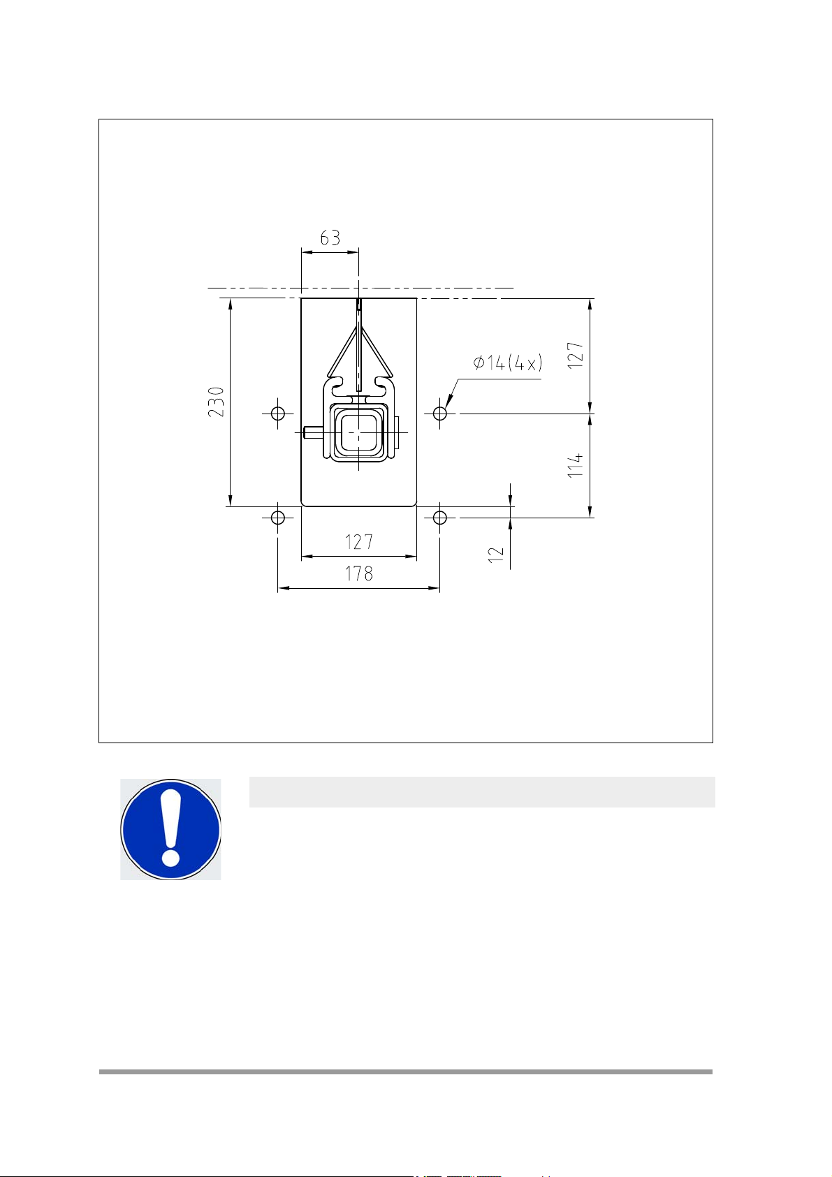
5. Starting from the point marked in step 4, sketch the cut-out for
the installation opening (6, Fig. 1) on the chute wall using the
dimensions from Fig. 2.
NOTE
The dimensions differ, depending on the tensioner or tensioner
variant used (Fig. 2).
The tensioner equipment bracket can be used as a template.
6. Use the dimensions from Fig. 2 to mark the installation holes
(7, Fig. 1) on the chute wall.
7. Create the cut-out for the installation opening at the points
marked in Step 5.
8. Drill the holes for the installation (Ø14 mm).
9. Repeat steps 1 to 8 on the far side.
Installation
© Martin Engineering GmbH 17 M3687UK-12/17
Page 20
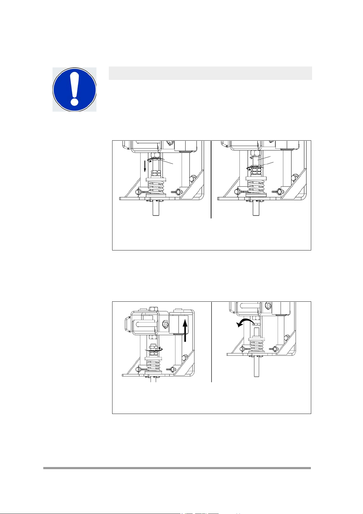
5.2.2 Conversion of the Bottom Mount spring tensioner to Top Mount
9
9
10
Installation
5.2.2.1 Operator side and far side
NOTE
The spring tensioner is delivered in the Bottom Mount variant as
standard.
Proceed as follows if spatial restrictions require a conversion from
Bottom Mount to Top Mount:
Fig. 3
1. Loosen the locknut SW32 (9, Fig. 3 left) clockwise and screw it
up to the hex nuts.
2. Unscrew the threaded rod (10, Fig. 3 right) with the locknut (9,
Fig. 3 right) clockwise.
Fig. 4
3. Slide the bracket all the way to the top.
4. Turn all of the locknuts and the adjusting nut counter-clockwise
and remove them from the threaded rod.
© Martin Engineering GmbH 18 M3687UK-12/17
Page 21
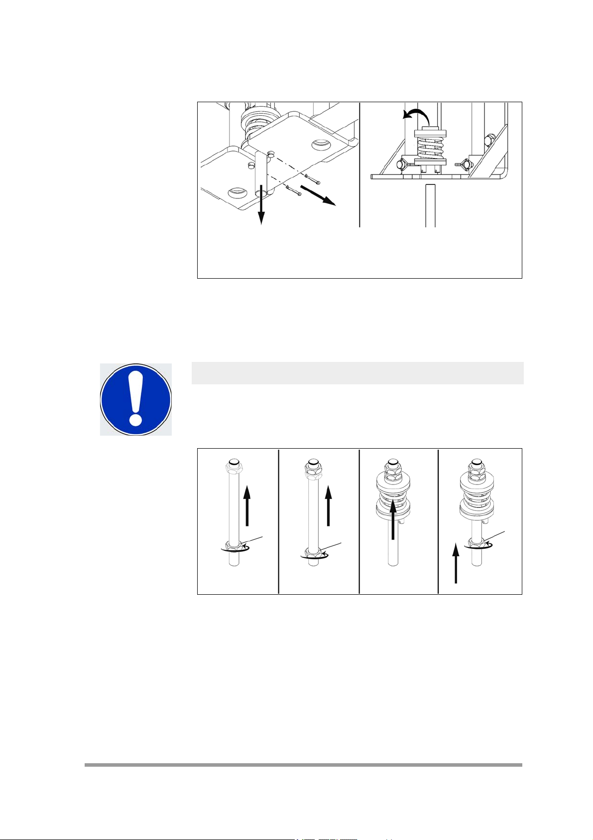
Fig. 5
9
9
9
5. Pull the threaded bolt (Fig. 5 left) downwards and remove it.
6. Remove the hammerlock cotter pins from the bolts (Fig. 5 left).
7. Remove the force spring with its washers and bolts (Fig. 5,
right).
Installation
NOTE
Please note during conversion that the threaded rod can only be
screwed in from one side.
The thread of the threaded rod is blocked on one side.
Fig. 6
8. Screw the hex nut (9) (Fig. 6 left) counter-clockwise onto the
threaded rod.
9. Screw the second hex nut (9) (Fig. 6 centre left) counterclockwise up to the first hex nut on the threaded rod.
10. Slide the tension spring with its washers and bolts (Fig. 6 centre
right) up to the hex nuts on the threaded rod.
11. Screw the counter hex nut (9) (Fig. 6 right) counter-clockwise,
as in the picture, onto the threaded rod.
© Martin Engineering GmbH 19 M3687UK-12/17
Page 22

Installation
14
2
1
2
Fig. 7
12. Remove locking bolts (14, Fig. 7). (omitted for the far side)
13. Remove the guide rods (2, Fig. 7). (omitted for the far side)
Fig. 8
14. Rotate the installation bracket (1, Fig. 8) by 180°. (omitted for
the far side)
NOTE
The spring tensioner on the far side is a mirrored version that on
the operator side.
15. Insert the guide rods (2, Fig. 8). (omitted for the far side)
© Martin Engineering GmbH 20 M3687UK-12/17
Page 23

Fig. 9
14
6
16. Insert the locking bolts (14, Fig. 8). (omitted for the far side)
Installation
Fig. 10
17. Insert the tension spring with threaded rod.
18. Use hammerlock cotter pins (6, Fig. 10) to secure the tension
spring bolt.
© Martin Engineering GmbH 21 M3687UK-12/17
Page 24

Installation
9
9
Fig. 11
19. Use the locknut (9, Fig. 11 left) to screw in the threaded rod.
20. Tighten the locknut (9, Fig. 11 right) and so secure the
threaded rod.
© Martin Engineering GmbH 22 M3687UK-12/17
Page 25

5.2.3 Replacing springs
4
7
8
4
4
7
8
4
NOTE
The spring must be replaced by a stronger version for belt widths
of 1400 mm or greater.
This is required for both sides.
Fig. 12
Installation
1. Perform steps 1 to 7 in Section 5.2.2 on both sides for removing
the tension spring.
2. Remove the individual parts (4, 7, 8, Fig. 12).
3. Replace these parts with the selected spare parts for the
stronger springs. (Also see Section 9.8 for spare parts).
4. Assemble the threaded rod as shown in Fig. 12.
NOTE
Figure 12 left – Bottom Mount.
Figure 12 right – Top Mount.
5. Reinstall the threaded rod.
© Martin Engineering GmbH 23 M3687UK-12/17
Page 26

5.2.4 Installing the tensioner
4
7
2
2
2
2
1
2
2
2
2
1
Installation
NOTE
The tensioners are pre-assembled by Martin Engineering before
shipment.
The tensioner is shipped in the Bottom Mount (Sec. 9.8)
installation option. The conversion to the Top Mount option must
be made before installation on the chute wall (Sec. 5.2.2).
Fig. 13
1. Screw the tensioner (1, Fig. 13) into the installation holes
(2, Fig. 13) on both sides of the chute wall.
NOTE
The tensioners on the operator side and the far side are not
identical. (Fig. 38, Sec. 9.8).
2. Remove the transport bolt (7, Fig. 13) from the mounting
bracket (4, Fig. 13).
© Martin Engineering GmbH 24 M3687UK-12/17
Page 27

5.2.5 Installing the cleaner
1
2
NOTE
The cartridge with the cleaner blades is pre-installed on the
mainframe by Martin Engineering before shipment.
Installation
Fig. 14
1. Insert the mainframe with the installed cartridge (1, Fig. 14) into
the mounting bracket from the operator side.
2. Slide the mainframe through the installation openings in the
mounting bracket on the far side (2, Fig. 14).
NOTE
The mainframe can be shortened if it protrudes too much on the
far side.
© Martin Engineering GmbH 25 M3687UK-12/17
Page 28

5.2.6 Securing the cleaner
17
18
17
Installation
Fig. 15: Operator side
1. Insert the hitch pins.
2. Insert the lock pin into the hitch pin.
Fig. 16: Far side
3. Use the screws (17, 18, Fig. 16) to secure the mainframe.
© Martin Engineering GmbH 26 M3687UK-12/17
Page 29

5.2.7 Centring the secondary cleaner beneath the conveyor belt
1
A
A
2
3
Fig. 17: Front view
Item Description
1 Chute wall
2 Driving drum
3 Blades
Installation
Tab. 3: Centring the secondary cleaner beneath the conveyor belt
NOTE
In the case of cleaner variants with an extended mainframe, an
initial rough centring is made by selecting the suitable adjustment
hole. The blades can then be centred as well.
© Martin Engineering GmbH 27 M3687UK-12/17
Page 30

5.2.8 Aligning the secondary cleaner in parallel to the driving drum
4
1
3
2
A
A
Installation
axis
Fig. 18: Top view
Item Description
1 Top view of the blades
2 Driving drum
3 Driving drum axis
4 Chute wall
Tab. 4: Top view of aligning the secondary cleaner in parallel to the
conveyor belt
NOTE
The installation must be repeated if the clearances are not
identical.
© Martin Engineering GmbH 28 M3687UK-12/17
Page 31

5.2.9 Aligning the secondary cleaner horizontally to the driving drum
4
A
A
2
1
3
axis
Fig. 19: Front view
Item Description
1 Driving drum
2 Driving drum axis
3 Blades
4 Chute wall
Installation
Tab. 5: Aligning the secondary cleaner horizontally
NOTE
The air tensioner must be re-installed if the clearances are not
identical.
NOTE
In the case of the spring tensioner, one side can be corrected
upwards if the clearances are not identical.
Loosen the locknuts (1, Fig. 20 left) for this.
The adjusting nut (2, Fig. 20 right) can be used to correct the
position upwards.
© Martin Engineering GmbH 29 M3687UK-12/17
Page 32

5.2.10 Tightening the cleaner
1
2
A A
Installation
Fig. 20
Adjusting the spring tensioner
1. Loosen the locknut (1, Fig. 20) on both sides.
2. Align the adjusting nuts (2, Fig. 20) evenly in a clockwise
direction on both sides until the cleaning blades slightly touch
the conveyor belt; then commence tensioning according to
Step 3 and the values from Table 6 or 7.
NOTE
The distance from the conveyor belt in this process must remain
identical over the entire length of the blade. Deviations must either
be corrected or the process must be started again from the
beginning.
Fig. 21
© Martin Engineering GmbH 30 M3687UK-12/17
Page 33

3. Turn the adjusting nuts equally clockwise on both sides until the
spring lengths of the tension springs (A, Fig. 21) are identical.
NOTE
The value required for the spring length (A) of the tension spring
can be found in Table 6 or 7.
Values for Top Mount design
Installation
Belt width
[mm]
400-500 57 1400-1600* 51
500-650 57 1600-1800* 51
650-800 54 1800-2000* 48
800-1000 54 2000-2200* 48
1000-1200 54 2200-2400* 44
1200-1400 51 2600-2800* 44
Tab. 6: Values - Top Mount
*A stronger spring is used for belt widths of 1400 mm and greater (Sec. 5.2.3).
Belt width
[mm]
400-500 38 1400-1600* 32
500-650 38 1600-1800* 32
650-800 35 1800-2000* 48
800-1000 35 2000-2200* 48
1000-1200 35 2200-2400* 44
1200-1400 32 2600-2800* 41
Spring length
[mm]
Values for Bottom Mount design
Spring length
[mm]
Belt width
[mm]
Belt width
[mm]
Spring length
[mm]
Spring length
[mm]
Tab. 7: Values - Bottom Mount
*A stronger spring is used for belt widths of 1400 mm and greater (Sec. 5.2.3).
© Martin Engineering GmbH 31 M3687UK-12/17
Page 34

Installation
WARNING RISK OF INJURY!
Body parts and/or clothing may get caught and pulled in by
rotating parts or by the moving conveyor belt.
Shut off the power supply to the conveyor system and its
accessories and secure it against unauthorised reactivation before
performing any installation or maintenance work.
Use warning signs!
CAUTION RISK OF DAMAGE!
Never operate the fully loaded belt cleaner for longer than 15
minutes on the running, unloaded conveyor belt. A risk of damage
due to overheating exists for the belt cleaner and/or the conveyor
belt.
Only operate the fully loaded belt cleaner on the running and fully
loaded conveyor belt.
CAUTION FLYING OBJECTS!
Forgotten tools or installation parts can fall off of the running
conveyor belt and cause minor injuries and property damage.
Always remove any tools from the work site and conveyor belt
upon completion of work before switching on the power supply.
4. Switch on the conveyor system.
5. Observe the cleaning action of the blades.
NOTE
The blades should contact the conveyor belt gently and without
vibration.
6. Stop the conveyor belt.
7. Shut off the conveyor system's power supply.
8. Readjust the spring tensioner if required.
9. Tighten the locking nuts against the adjusting nuts on both
sides.
© Martin Engineering GmbH 32 M3687UK-12/17
Page 35

Adjusting the air tensioner
13
1
12
11
4
3
9
2
5
10
8
6
7
14
15
Installation
Fig. 22
Item Description
1 Pressure gauge
2 Air bellows on the operator side
3T-piece
4 Compressed air connection to the compressed air
system
5 Compressed air hose on the operator side
6 Mainframe
7 Compressed air hose on the far side
8 Air bellows on the far side
9 Compressed air connection on the operator side
10 Compressed air connection of the air bellows on the far
Tab. 8: Compressed air supplies
side
11 Ball valve
12 External compressed air connection
13 Housing
14 Handle
15 Hitch pin
© Martin Engineering GmbH 33 M3687UK-12/17
Page 36

Installation
1. Push the compressed air hose (5, Fig. 22) through the
mainframe (6, Fig. 22) onto the operator side.
NOTE
Route the compressed air hose under the hitch pin and handle
when pushing it through the mainframe.
2. Fasten the compressed air hose (7, Fig. 22) to the connection
(10, Fig. 22) of the air bellows (8, Fig. 22) on the far side.
NOTE
The compressed air hose may be longer than the required length.
Shorten it to the suitable length if required.
3. Plug the end of the compressed air hose into one connection of
the T-piece (3, Fig. 22) on the operator side.
4. Plug the T-piece into the connection (9, Fig. 22) of the air
bellows (2, Fig. 22) on the operator side.
5. Connect the third junction of the T-piece (4, Fig. 22) to the
compressed air system (1, Fig. 22).
6. A pressure from Table 9 must be applied to both sides of the air
bellows.
Belt width
[mm]
400-500 0.34 1400-1600 0.97
500-650 0.41 1600-1800 1.03
650-800 0.55 1800-2000 1.24
800-1000 0.69 2000-2200 1.45
1000-1200 0.76 2200-2400 1.59
1200-1400 0.90 2600-2800 1.72
Tab. 9: Compressed air values
Required pressure
[bar]
Belt width
[mm]
Required pressure
[bar]
© Martin Engineering GmbH 34 M3687UK-12/17
Page 37

NOTE
Steps 7 - 12 must be performed for an Air Regulator Kit supplied
by Martin Engineering.
If an existing Air Regulator Kit is used, then follow its operating
instructions to set the appropriate contact pressure (Tab. 8).
7. Connect the ball valve (11, Fig. 22) to the external compressed
air supply (12, Fig. 22).
8. Switch on the external compressed air supply.
9. Open the ball valve.
NOTE
The cleaner is raised and the blades touch the conveyor belt
10. Open the housing (13, Fig. 22).
11. Unlock the pressure reducer on the Air Regulator Kit.
12. Set the contact pressure specified in Table 9.
Installation
NOTE
The pressure reducer is equipped with a self relieving diaphragm
which automatically stabilises the pressure. A certain waiting
period is required every time the setting is changed
to relieve any excess pressure.
13. Lock the pressure reducer when the suitable contact pressure
is reached.
14. Close the housing.
© Martin Engineering GmbH 35 M3687UK-12/17
Page 38

5.3 Operation with loading
4
3
2
4
1
51mm
Installation
WARNING RISK OF INJURY!
Body parts and/or clothing may get caught and pulled in by
rotating parts or by the moving conveyor belt.
Shut off the power supply to the conveyor system and its
accessories and secure it against unauthorised reactivation before
performing any installation or maintenance work.
Use warning signs!
NOTE
Figure 23 is an example of a cleaner.
Fig. 23
1. If the secondary cleaner (4, Fig. 23) raises the conveyor belt
(1, Fig. 23), then a pressure roller (2, Fig. 23) must be installed
above the contact point between the blade and conveyor belt at
a clearance of 51 mm against the running direction (3, Fig. 23)
to support the conveyor belt.
2. Remove all tools and fire protection covers from the installation
site and the conveyor belt.
3. Operate the conveyor system for one hour under load.
© Martin Engineering GmbH 36 M3687UK-12/17
Page 39

CAUTION RISK OF DAMAGE!
Never operate the fully loaded belt cleaner for longer than 15
minutes on the running, unloaded conveyor belt. A risk of damage
due to overheating exists for the belt cleaner and/or the conveyor
belt.
Only operate the fully loaded belt cleaner on the running and fully
loaded conveyor belt.
4. Shut off the conveyor belt system after the one-hour operation
under load, shut off the power supply and secure it against
unauthorised reactivation.
5. Check whether all of the fastening parts are securely tightened.
Tighten any loose connections.
6. Inspect the belt cleaner for the following conditions:
• Wear: minor phase-in wear is normal. This stops as soon
as the blades have adjusted to the shape of the conveyor
belt.
• Bulk material accumulation: No bulk materials may
accumulate between the blades and return side.
7. Note the corresponding information in Section 7
"Troubleshooting" in cases of excess wear, bulk material
accumulation or other problems.
Installation
© Martin Engineering GmbH 37 M3687UK-12/17
Page 40

5.4 Placement of warning labels and warning tags
No. 23395
! WARNUNG
Körperteile und/oder Kleidung können durch rotierende Bauteile oder durch das
sich bewegende Förderband eingezogen werden. Vor jeglichen Installations- bzw.
Wartungsarbeiten die Stromversorgung zur Förderbandanlage und dessen Zubehör
abschalten und gegen unbefugtes Einschalten sichern.
Warnschilder verwenden!
No. 30528
Quetschgefahr
! WARNUNG
Installation
Fig. 24
© Martin Engineering GmbH 38 M3687UK-12/17
Page 41

6 Maintenance
6.1 Safety information
WARNING RISK OF INJURY!
Body parts and/or clothing may get caught and pulled in by
rotating parts or by the moving conveyor belt.
Shut off the power supply to the conveyor system and
accessories and secure it against unauthorised reactivation before
performing any maintenance work.
Use warning signs!
NOTE
Maintenance inspections must be performed at least once a week.
Shorter maintenance intervals may be required depending on the
operating conditions.
Maintenance
its
NOTE
The item numbers in the pictures correspond to the numbering in
the parts list in Section 9.
6.2 Weekly maintenance
1. Shut off the power supplies of the conveyor belt and any
additional equipment and secure them against unauthorised
reactivation.
2. Remove all material deposits from the blade and the
mainframe.
3. Inspect whether all of the fastening parts are securely
tightened. Tighten any loose connections.
4. Check the cleaner force and re-tighten if necessary.
5. Check the blades for wear, damage and missing parts.
© Martin Engineering GmbH 39 M3687UK-12/17
Page 42

Maintenance
NOTE
Take the corresponding parts of the conveyor system out of
service if any indications of functional disturbances are noticed.
Contact Martin Engineering or one of its representatives for
support. Do NOT start up the conveyor system until the cause of
the problems has been recognised and eliminated.
CAUTION RISK OF DAMAGE!
Blades must not be worn out beyond the wear line; this can cause
serious material damage.
Inspect the blades regularly and replace them in good time!
6. Follow the instructions in Section 6.3 to replace any worn out
blades.
7. Clean all the warning labels. Replace illegible warning labels
immediately. Warning labels can be purchased from Martin
Engineering or a contracted dealer.
CAUTION FLYING OBJECTS!
Forgotten tools or installation parts can fall off of the running
conveyor belt and cause minor injuries and property damage.
Always remove any tools from the work site and conveyor belt
upon completion of work before switching on the power supply.
8. Remove all tools from the working area.
9. Switch on the conveyor system.
© Martin Engineering GmbH 40 M3687UK-12/17
Page 43

WARNING RISK OF INJURY!
Body parts and/or clothing may get caught and pulled in by
rotating parts or by the moving conveyor belt.
Do not touch or reach into the conveyor system or its accessories
during operation.
CAUTION RISK OF DAMAGE!
Never operate the belt cleaner for longer than 15 minutes on the
running unloaded conveyor belt. A risk of damage due to
overheating exists for the belt cleaner and/or the conveyor belt.
Never operate the belt cleaner unless the conveyor belt is running.
10. Observe the cleaner and check its cleaning performance.
Maintenance
© Martin Engineering GmbH 41 M3687UK-12/17
Page 44

6.3 Replacing the blades
1
2
Maintenance
WARNING RISK OF INJURY!
Body parts and/or clothing may get caught and pulled in by
rotating parts or by the moving conveyor belt.
Before any installation or maintenance work is carried out, ensure
that all power sources to the conveyor belt system and its
accessories are switched off and secured against unauthorised
reactivation. Use warning signs!
Fig. 25
1. Loosen the tensioner.
• Spring tensioner: Loosen the locknuts (1, Fig. 25) and
adjusting nuts (2, Fig. 25) on both sides.
• Air tensioner: Shut off the compressed air supply.
2. Completely retract the tensioner.
• Spring tensioner: Turn the locknuts (1, Fig. 25) fully
upwards. Loosen the adjusting nuts (2, Fig. 25) equally on
both sides and turn them completely upwards.
• Air tensioner: Bleed the compressed air line.
© Martin Engineering GmbH 42 M3687UK-12/17
Page 45

Fig. 26
Maintenance
3. Remove the locking pin.
Fig. 27
4. Release and remove the hitch pin's locking pin.
5. Remove the hitch pin.
© Martin Engineering GmbH 43 M3687UK-12/17
Page 46

Maintenance
6
10
10
Fig. 28
6. Pull the cleaner cartridge out of the mainframe by its handle
(6, Fig. 27).
7. The cartridge must be placed on a stable support (e.g. a table).
8. Clean the blades.
9. Replace worn-out blades as follows
Fig. 29
NOTE
If both end stops are to be removed, then first mark their position
in the cartridge so that the blades can be correctly positioned
following the re-assembly.
The blades must be realigned on the cartridge if the positions were
not marked. (Sec.5.2.5 ff).
© Martin Engineering GmbH 44 M3687UK-12/17
Page 47

Fig. 30
2
1
Belt travel direction
a) Remove one or both end stops (10, Fig. 28).
b) Remove the blades (1, Fig. 29) from the cartridge.
NOTE
The screwed-on lateral guidance (2, Fig. 29) can be additionally
removed if the blades are stuck.
The lateral guidance must be reinstalled before the new blades
can be inserted.
Maintenance
Fig. 31
NOTE
Ensure alignment with the running direction of the conveyor belt
when in-line blades are used.
Please ensure when reversing blades are used that no gaps form
between the blades since these protrude on one side and
interlock.
© Martin Engineering GmbH 45 M3687UK-12/17
Page 48

Maintenance
10
10
10
Fig. 32
c) Insert new blades (1, Fig. 31) into the cartridge.
d) Slide in the blade up to the stop (Fig. 31).
Fig. 33
e) Insert the end stops (10, Fig. 32).
NOTE
Note the markings made previously if both end stops were
removed.
© Martin Engineering GmbH 46 M3687UK-12/17
Page 49

Fig. 34
6
Maintenance
10. Slide the cartridge by its grip (6, Fig. 33) onto the mainframe
(1, Fig. 33).
Fig. 35
11. Insert the hitch pin.
12. Insert the locking pin into the hitch pin.
© Martin Engineering GmbH 47 M3687UK-12/17
Page 50

13. Tension the locking screws on the far side.
14. Check the screw connections for tight fit and re-tighten when
necessary.
15. Tension the cleaner.
NOTE
Maintenance
The position of the cleaner and/or tensioner may need to be
readjusted (Sec. 5.2.4 et seq.).
© Martin Engineering GmbH 48 M3687UK-12/17
Page 51

7 Troubleshooting
7.1 Safety information
NOTE
The product is exposed to highly diverse bulk materials and is
often used under extreme operating and environmental conditions.
Malfunctions other than those listed below can therefore occur.
In this case, either Martin Engineering or one of its representatives
can assist with the positioning or with special solutions. Do not
start up the conveyor system again until the fault has been
recognised and cleared.
7.2 Troubleshooting
Check the following items if excessively high wear on the blades
and/or unsatisfactory cleaning performance are/is noticed
subsequent to installation:
Troubleshooting
Symptom Cause Remedy
High wear on the
blades.
Insufficient cleaning
performance and bulk
material
accumulation.
Unusual pattern of
wear or damage to
the blade.
Noises or vibrations. Cleaner force on the
The blade is too tightly
pressed on the cleaner.
The blade is not pressed
sufficiently or is pressed
excessively onto the
conveyor belt.
The blades are worn. Inspect the blades and replace if
Damaged conveyor belt or
connection points.
Different tension values of
the inline reversing
tensioner.
conveyor belt too light or too
heavy.
The blade's urethane is
possibly not suitable for the
application.
Blade not correctly aligned
with the conveyor belt.
Reduce the force. Values
(Sec. 5.2.8 Tab.6 or Tab.8),
Increase or reduce the force.
necessary. (See “Weekly
maintenance”).
Inspect the conveyor belt's
connection points and repair or
replace as needed.
Check the tension values and
possibly re-tighten.
Correct the force if necessary.
Contact Martin Engineering or one
of its representatives.
Align the blade (Sec. 5.2.4 ff).
Tab. 10: Troubleshooting
© Martin Engineering GmbH 49 M3687UK-12/17
Page 52

Symptom Cause Remedy
Corrosion or chemical
decomposition.
Deflection of the
mainframe.
Troubleshooting
The blades are
pushed out of the
tracks.
Tab. 10: Troubleshooting
The blade's urethane is
possibly not suitable for the
application.
Extremely high tension. Reduce the force on the blades to
The blade is too heavily
loaded.
Contact Martin Engineering or one
of its representatives.
the highest recommended value
specified in the installation
instructions
be seen as normal. Contact Martin
Engineering if very large deflection
occurs).
Reduce air pressure or spring
force.
(a slight deflection is to
© Martin Engineering GmbH 50 M3687UK-12/17
Page 53

8 Storage, De-installation, Disposal
8.1 Packing and transportation
The products described here are packed and shipped by Martin
Engineering.
The products may be transported solely in the Martin Engineering
packaging.
The logistics company in charge of the shipment shall be
responsible for any damage and/or loss.
8.2 Storage
To ensure optimal function of the product Martin Engineering
recommends storing its components in a dry place at room
temperature where they are protected against direct sunlight.
The best storage conditions are at temperatures ranging from
+0 °C to +30 °C and 60% relative humidity.
Storage, De-installation, Disposal
Martin Engineering guarantees that the stored products will remain
fully functional for at least 2 years under the storage conditions
specified here.
8.3 De-installation
The de-installation is carried out in the reverse order to that of the
installation (see Section 5.2.2).
8.4 Disposal
Assemblies and/or single parts of the Martin Engineering products
must be professionally disposed of after usage as follows.
• Complete assemblies must be dismantled, sorted by
material type, and separately disposed of.
All nationally and internationally applicable disposal regulations are
to be complied with when disposing of the product.
© Martin Engineering GmbH 51 M3687UK-12/17
Page 54

9Part numbers
Part numbers
9.1 Explanation of part numbers
This section lists the product designations with their associated part
numbers for the MARTIN
accessories.
Please indicate the part numbers in every order.
MARTIN® DT2S secondary cleaner
DT2S-aabccddef+E
a Belt width in inches
b Blade design
T: Reversing blade with tungsten carbide
S: Reversing blade made from stainless steel
U: Reversing blade made from urethane
c Cleaning width in inches
d Urethane colour
BR: Brown (resistant to chemicals)
GR: Green (resistant to temperature)
OR: Orange
e Mainframe options
P: Mild steel (1.0037) - painted (RAL 2004)
E: Mild steel (1.0037) - extended - painted (RAL 2004)
S: Stainless steel (1.4571)
f Tensioner options
S: Spring tensioner
A: Air tensioner
®
DT2S Secondary Cleaner and its
© Martin Engineering GmbH 52 M3687UK-12/17
Page 55

MARTIN® DT2SC secondary cleaner cartridge
DT2SC-aabccdde
a Belt width in inches
b Blade design
Ø: No blades
T: Reversing blade with tungsten carbide
S: Reversing blade made from stainless steel
U: Reversing blade made from urethane
c Cleaning width in inches
d Urethane colour
ØØ: No blades
BR: Brown (resistant to chemicals)
GR: Green (resistant to temperature)
OR: Orange
e Parameter description
P: Mild steel (1.0037) - painted (RAL 2004)
S: Stainless steel (1.4571)
Part numbers
© Martin Engineering GmbH 53 M3687UK-12/17
Page 56

9.2 Martin® Inspection Doors
Part numbers
9.3 Accessories
With standard rubber door, up to 177° C:
• 229 x 305 mm: Part no. CYAR-0912.
• 305 x 356 mm: Part no. CYAR-1214.
• 305 x 457 mm: Part no. CYAR-1218.
• 457 x 610 mm: Part no. CYAR-1824.
• 610 x 610 mm: Part no. CYAR-2424.
With steel door (dust-proof):
• 229 x 305 mm: Part no. CYA-0912.
• 305 x 356 mm: Part no. CYA-1214.
• 305 x 457 mm: Part no. CYA-1218.
• 457 x 610 mm: Part no. CYA-1824.
• 610 x 610 mm: Part no. CYA-2424.
• Reversing installation brackets (pair)
Part no. 33288
• Reversing installation brackets (single)
Part no. 33282
• Reversing "Z" bracket
Part no. 31158; for use with MARTIN
®
Inspection doors.
9.4 Warning labels / Warning tags
• Conveyor Products Warning Label:
Part no. 23395
• Crushing Hazard Warning Label:
Part no. 30528
© Martin Engineering GmbH 54 M3687UK-12/17
Page 57

9.5 MARTIN® DT2S Secondary cleaner
Part numbers
Fig. 36
© Martin Engineering GmbH 55 M3687UK-12/17
Page 58

Part numbers
© Martin Engineering GmbH 56 M3687UK-12/17
Page 59

Part numbers
© Martin Engineering GmbH 57 M3687UK-12/17
Page 60

9.6 MARTIN® DT2SC Secondary cleaner cartridge
AL = Adaptor Length / Aufnahmelänge
CL = Cartouche Length / Kartuschenlänge
7
7 9
8
10
1
2
3
4
5
6
11
Part numbers
Fig. 37
© Martin Engineering GmbH 58 M3687UK-12/17
Page 61

Part numbers
ND
Item /
Pos.
Qty. /
Anz.
Description / Beschreibung P/N / Teile-Nr.
11
DT2S split track mainframe / DT2S Hauptrahmen mit geteilter
Blattaufnahme
s.C. / s.T.
2 1 Durt Tracker Split frame / Seitenführung s.C. / s.T.
3 s.C. / s.T. Washer flat 1/2" wide / Unterlegscheibe breit s.C. / s.T.
4 s.C. / s.T. Nut hex elastic lock 1/2" / Selbstsichernde Sechskantmutter s.C. / s.T.
5 1 DT2S end cap / DT2S End Kappe 37705
6 1 Gripp handle / Griff s.C. / s.T.
7 2 Washer flat 3/8" wide / Unterlegscheibe breit s.C. / s.T.
8 1 Hexagon head screw 3/8" x 4-1/2" / Sechskantschraube s.C. / s.T.
9 1 Nut hex elastic lock 3/8" / Selbstsichernde Sechskantmutter s.C. / s.T.
10 2 End stop / Endanschlag s.C. / s.T.
11 2 Hexagon head screw 3/8" x 1-1/2" / Sechskantschraube s.C. / s.T.
Part number /
Teilenummer
DIM P/N Item / Teile-Nr. Pos.
Qty. item /
Anz. Pos.
AL CL 1* 2* 3,4
DT2SC-18XXXXXXX 686 918 37717-18 34423-30 2
DT2SC-24XXXXXXX 838 1071 37717-24 34423-36 3
DT2SC-30XXXXXXX 991 1223 37717-30 34423-42 3
DT2SC-36XXXXXXX 1143 1376 37717-36 34423-48 4
DT2SC-42XXXXXXX 1295 1528 37717-42 34423-54 4
DT2SC-48XXXXXXX 1448 1680 37717-48 34423-60 5
DT2SC-54XXXXXXX 1600 1833 37717-54 34423-66 5
DT2SC-60XXXXXXX 1753 1985 37717-60 34423-72 5
DT2SC-66XXXXXXX 1905 2138 37717-66 34423-78 6
DT2SC-72XXXXXXX 2057 2290 37717-72 34423-84 6
DT2SC-84XXXXXXX 2362 2595 37717-84 34423-96 7
DT2SC-96XXXXXXX 2667 2900 37717-96 34423-108 8
*If Option "S" is selcted add at P/N 1 "-316SS" and at P/N 2 "N"
Wenn Option "S" gewählt ist dann an Teilenr. von Pos. 1 ein "-316SS" anhängen und
an Teilenr. von Pos. 2 ein "N" anhängen
Part number /
Teilenummer
P/N Item / Teile-Nr. Pos.
3 4 6 7 8 9 10 11
DT2SC-XXXXXXXPX 17328 18577 36313 18007 34082 14201 30386 15673
DT2SC-XXXXXXXSX 35913 SPO3938-02 36313-316SS 37471 37764 SPO3938-12 30386-N SPO3938-13
Part number /
Teilenummer
P/N Item / Teile-Nr. Pos.
3 4 6 7 8 9 10 11
DT2SC-XXXXXXXPX 17328 18577 36313 18007 34082 14201 30386 15673
DT2SC-XXXXXXXSX 35913 SPO3938-02 36313-316SS 37471 37764 SPO3938-12 30386-N SPO3938-13
Part number /
Teilenummer
DIM P/N Item / Teile-Nr. Pos.
Qty. item /
Anz. Pos.
AL CL 1* 2* 3,4
DT2SC-18XXXXXXX 686 918 37717-18 34423-30 2
DT2SC-24XXXXXXX 838 1071 37717-24 34423-36 3
DT2SC-30XXXXXXX 991 1223 37717-30 34423-42 3
DT2SC-36XXXXXXX 1143 1376 37717-36 34423-48 4
DT2SC-42XXXXXXX 1295 1528 37717-42 34423-54 4
DT2SC-48XXXXXXX 1448 1680 37717-48 34423-60 5
DT2SC-54XXXXXXX 1600 1833 37717-54 34423-66 5
DT2SC-60XXXXXXX 1753 1985 37717-60 34423-72 5
DT2SC-66XXXXXXX 1905 2138 37717-66 34423-78 6
DT2SC-72XXXXXXX 2057 2290 37717-72 34423-84 6
DT2SC-84XXXXXXX 2362 2595 37717-84 34423-96 7
DT2SC-96XXXXXXX 2667 2900 37717-96 34423-108 8
*If Option "S" is selcted add at P/N 1 "-316SS" and at P/N 2 "N"
Wenn Option "S" gewählt ist dann an Teilenr. von Pos. 1 ein "-316SS" anhängen und
an Teilenr. von Pos. 2 ein "N" anhängen
© Martin Engineering GmbH 59 M3687UK-12/17
Page 62

9.7 MARTIN® DT2S Spring tensioner
264
min. 94
max. 197
146
44,45 (51)
286
10
14
20
17
5
9
22
2
18
6
17
15
23
9
12
21
25
25
24
4
26
19
15
s.N. / s.B.
11
9
4
1
16
7
13
8325
s.N. / s.B.
Top mount
min. 68
max. 110
Far side /
Gegenüberliegende Seite
Operator side /
Bedienerseite
s.N. / s.B.
s.N. / s.B.
Bottom mount
Part numbers
Fig. 38
© Martin Engineering GmbH 60 M3687UK-12/17
Page 63

Part numbers
ND
Item /
Pos.
Qty. /
Anz.
Description / Beschreibung P/N / Teile-Nr.
1 2 Inline mount plate / Installationskonsole 37701
2 4 Guide rod / Führungsstange 37702
3 2 Spring retainer / Federaufnahme 33594
4 4 Washer flat 1-1/4" wide / Unterlegscheibe breit 33951
5 4 Clevis pin 3/8" x 7/8" / Bolzen 33949
6 4 Cotter pin 1/8" x 1-3/4" / Splint 16578
7 2 Spring Ø2" x 1-3/4" / Feder 33602
8 2 Spring retainer / Federaufnahme 33594-01
9 6 Hex nut jam low 3/4" / Sechskantmutter niedrig 38219
10 2 Adjustment rod / Gewindestange 37706
11 1
Slide Bracket (Operators side) / Aufnahmekonsole
(Bedienerseite)
37703-OS
12 4 UHMW sleeve / Führungshülse 37704
13 1
Slide bracket (Operator's side) / Führungswinkel
(Bedienerseite)
37703-OSTOP
14 4 Wire lock pin 3/8" x 1-3/4" / Arretierbolzen 37126
15 1 Hitch pin 3/4" x 1-3/4" w/chain / Steckbolzen mit Kette 38073
16 8 Washer flat 1/2" thick / Unterlegscheibe dick 19126
17 9
Hexagon head screw 1/2" x 1-1/2" /
Sechskantschraube
22766
18 8 Washer compression 1/2" / Unterlegscheibe 24310
19 8 Hex nut 1/2" / Sechskantmutter 17151
20 1 Slide bracket / Aufnahmekonsole 37703
21 1 Far side strap / Lasche (Gegenüberliegende Seite) 37715
22 1
Slide bracket saddle top (far side) / Führungswinkel
(Gegenüberliegende Seite)
37713-FSTOP
23 2
Hexagon head screw 1/2" x 2-1/2" /
Sechskantschraube
26139
x 24 2 Spring Ø2" x 2" / Feder 38026
x 25 4 Washer flat 3/4" wide / Unterlegscheibe breit 20164
26 4
Ext retaining ring f/1,5" shaft / Sprengring für Ø1,5"
Schaft
38301
Replace Pos. 7 with Pos. 24 and Pos. 4 and Pos. 8 with Pos. 25 for belt widths above 54 (1400) /
Für Förderbandbreiten über 1400 mm Pos. 7 gegen Pos. 24 und Pos. 4 und Pos. 8 gegen Pos. 25
austauschen
Pos. 16-19 are partial shipped loose / Pos. 16-19 sind teilweise lose beigelegt
© Martin Engineering GmbH 61 M3687UK-12/17
Page 64

9.8 MARTIN® DT2S Air tensioner
159
294
264
Operator side /
Bedienerseite
Far side /
Gegenüberliegende Seite
14
18
16
19
6
13
10
7
17
12
7
1
3
2
5
11
4
8
9
15
Part numbers
Fig. 39
© Martin Engineering GmbH 62 M3687UK-12/17
Page 65

Part numbers
ND
Item /
Pos.
Qty. /
Anz.
Description / Beschreibung P/N / Teile-Nr.
1 2 Inline mount plate / Installationskonsole 37701
2 4 Guide rod / Führungsstange 37702
3 2 Air bag / Luftbalg 30587
41
Slide Bracket (Operators side) / Aufnahmekonsole
(Bedienerseite)
37703-OSA
5 4 UHMW sleeve / Führungshülse 37704
6 4 Wire lock pin 3/8" x 1-3/4" / Arretierbolzen 37126
7 1 Hitch pin 3/4" x 1-3/4" w/chain / Steckbolzen mit Kette 38073
8 8 Washer flat 1/2" thick / Unterlegscheibe dick 19126
9 8 Hexagon head screw 1/2" x 1-1/2" / Sechskantschraube 22766
10 8 Washer compression 1/2" / Unterlegscheibe 24310
11 8 Hex nut 1/2" / Sechskantmutter 17151
12 4
Socket head screw 3/8" x 3/4" / Zylinderschraube mit
Innensechskant
36510
13 4 Washer compression 3/8" / Unterlegscheibe 11747
14 4 Hexagon head screw 3/8"-16NC X 1" / Sechskantschraube 11746-02
15 1
Slide bracket (Far side) /
Aufnahmekonsole (Gegenüberliegende Seite)
37703-A
16 1 Far side strap / Lasche (Gegenüberliegende Seite) 37715
17 2 Square head screw 1/2"-13NC X 2" / Vierkantschraube 22763-06
18 1 Square head screw 1/2"-13NC X 1-1/2" / Vierkantschraube 33190
19 4 Ext retaining ring f/1,5" shaft / Sprengring für Ø1,5" Schaft 38301
Pos. 8-11 are shipped loose / Pos. 8-11 sind lose beigelegt
© Martin Engineering GmbH 63 M3687UK-12/17
Page 66

10 Declaration of Incorporation
Declaration of incorporation in accordance with
Machinery Directive (2006/42/EC) Annex II B
for the installation of an incomplete machine
Declaration of Incorporation
We, Martin Engineering,
In der Rehbach 14 Tel.: +49 6123-97820
D-65396 Walluf Fax: +49 6123-75533
herewith declare that the product named in the following
Product designation:
Conveyor belt cleaner
of make / type:
MARTIN
with serial number:
meets the following requirements:
Machinery Directive 2006/42/EC
DIN EN 618 - Equipment and systems for bulk materials
The following harmonised standards in particular were applied:
DIN EN ISO 12100 Safety of Machinery
Notified body:
The installation instructions belonging to the product and the technical documentation are
enclosed with the product in their original version.
®
DT2S secondary cleaner
not required
not required
The commissioning of this product is prohibited until it has been determined that the system in
which it is to be installed meets the requirements of versions 98/37/EC and 2006/42/EC of the
EC Directive.
Date: 21/01/2010
Manufacturer's signature: Managing director, Michael Hengl
© Martin Engineering GmbH 64 M3687UK-12/17
Page 67

PROBLEM SOLVED
™
Publication no. M3687UK-12/17 ©MARTIN ENGINEERING 2016
USA (Headquarters)
Martin Engineering
One MartinF Place, 61345 Neponset (Illinois), USA
Phone +1 (800) 544-2947; Fax +1 (800) 814-1553
info@martin-eng.com; www.martin-eng.com
European subsidiaries
Germany (Main European branch)
Martin Engineering GmbH
In der Rehbach 14, 65396 Walluf, Germany
Tel. +49 6123 9782 0; Fax +49 6123 75533
info@martin-eng.de; www.martin-eng.de
Great Britain
Martin Engineering Ltd.
8, Experian Way, NG2 Business Park,
Nottingham NG2 1EP, Nottinghamshire, Great Britain
Tel +44 115 946 4746; Fax +44 115 946 5550
info@martin-eng.co.uk; www.martin-eng.co.uk
France
Martin Engineering SARL
50 Avenue d‘Alsace, 68025 Colmar Cedex, France
Tel +33 389 20 63204; Fax +33 389 20 4379
info@martin-eng.fr; www.martin-eng.fr
Russia
OOO Martin Engineering
Ul. Bolshaya Dmitrovka, 23/1
125009 Moscow, Russia
Tel +7 495 181 33 43; Fax +7 499 720 62 12
info@martin-eng.ru; www.martin-eng.ru
Turkey
Martin Engineering Türkiye
Yukarı Dudullu İmes Sanayi Sitesi, B Blok 205 Sokak No.6
34775 Ümraniye Istanbul, Turkey
Tel +90 216 499 34 91; Fax +90 216 499 34 90
info@martin-eng.com.tr; www.martin-eng.com.tr
Italy
Martin Engineering Italy Srl
Via Buonarroti, 43/A, 20064 Gorgonzola (MI), Italy
Tel +39 295 3838 51; Fax +39 295 3838 15
info@martin-eng.it; www.martin-eng.it
Quality management system certified by DNV - ISO 9001
Subject to technical modifications
 Loading...