

Page 1
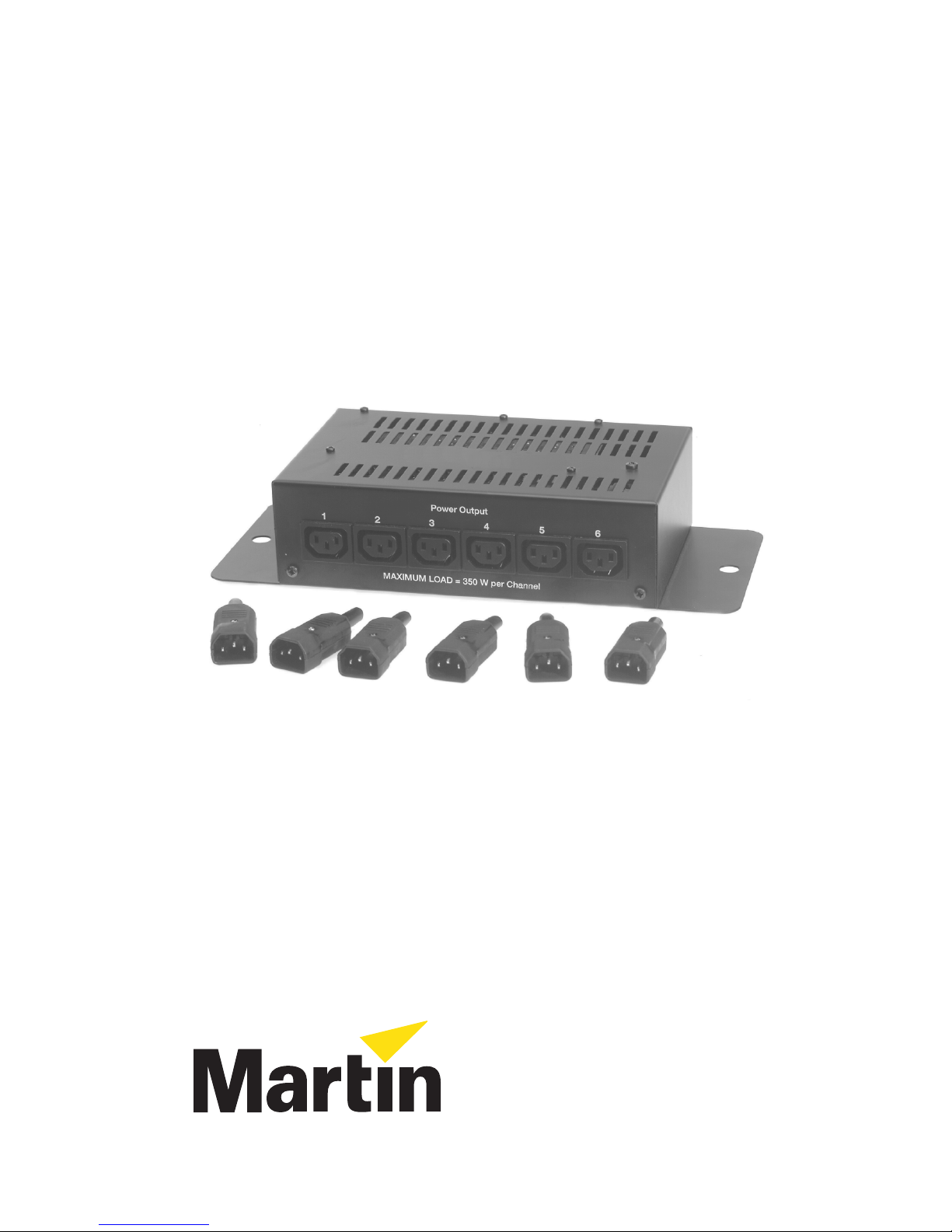
DMX Switch Pack
User Manual
EU version shown
P/N 35000010
Page 2

© 1998 - 1999 Martin Professional A/S, Denmark.
All rights reserved. No part of this manual may be
reproduced, in any form or by any means, without
permission in writing from Martin Professional A/S,
Denmark.
Printed in Denmark.
P/N 35000010 Rev.B, 990713
Page 3

Thank you for selecting the Martin DMX Switch Pack. This DMX-controlled switching
device allows y ou to turn on and off up t o six 35 0 wa tt d ev ice s wit h th e Mar tin 25 18 DMX
Controller or any other DMX board. It allows you to control non-intelligent lights; it is
ideal for combining fixtures from Martin’s DJ Series with intelligent lights.
The DMX Switch Pack is ruggedly bui lt for years of troub le-free us e. Setup and opera tion
are simple; please read this manual before setting up and operating the device.
Safety information
This product presents risks of lethal or severe injury.
This product is for professional use only. It is not for household use. Read this manual
before powering or installing the fixture, follow the safety precautions listed below and
observe all warnings in this manual and printed on the fixture. If you have questions about
how to operate the fixture sa fely, please contact your Martin dealer or call th e Martin 24hour servic e hotline at +45 70 200 201.
WARNING!
To protect yourself and others from electric shock
• Disconnect the fixture from AC power before removing or installing fuses or any part,
and when not in use.
• Always ground (earth) the fixture electrically.
• Use only a source of AC power that complies with local building and electrical codes
and has both overload and ground-fault protection.
• Do not expose the fixture to rain or moisture.
• Refer all service to a qualified technician.
• Never operate the fixture with missing or damaged covers.
To protect yourself and others from burns and fire
• Never use the device to power fixtures that exceed the specified maximum load.
• Never attempt to bypass the fuses.
• Always replace defective fuses with ones of the specified type and rating.
• Do not modify the fixture or install other than genuine Martin parts.
To protect yourself and others from injury due to falls
• When suspending the fixture above ground le vel, verify that the structure can hold at
least 10 times the weight of all installed devices.
• Secure the device with a safety wire threaded throug h the side holes.
• Block access below the work area whenever installing or removing the fixture.
3User Manual
Page 4

Setup
The DMX Switch Pack comes with a 5 meter shielded 3-pin XLR cable. In addition, the EU
version includes 6 standard male IEC plugs for connecting fixtures.
The following installation steps are required:
1.
2.
3.
4.
Install plug
The switch pack is delivered with no plug on the power cord. Following the manufacturer’s
instruction s , in stall an approved 3- prong grounding-type p lug that fits your supp ly. Connec t
the wires to the pins as listed below. The table shows some possible pin identification
schemes; if the pin s are n ot cle a rly ide n tified, or if you have any doubts a bo ut pro per in sta llation, consult a qualified electrician.
Install a plug on the power cord
Install IEC plugs on the fixtures (EU version only)
Connect the data link
Set the DMX address
Table 1: Plug Wiring
Wire (EU) Wire (US) Pin Marking Screw (US)
brown black live “L” yellow or brass
blue white neutral “N” silver
yellow/green green ground green
Connect data link
Connect the data link cable to the “In” jack using a 3-pin female XLR connector. If using 5pin cables, a 5-pin male to 3-p in female cable su ch as Martin P/N 30 9160 must be used.
(Pins 4 and 5 are not used.)
Continue the data l ink by connecting the cab le to the “Out” jack; use a 3-pi n XLR male
connector. Insert a termination plug in the “Out” jack if the switch pack is the last device on
the link. A termination plug is simply a 3-pin male XLR connector with a 120 ohm resistor
soldered between pins 2 and 3.
Connect fixtures, EU version
IEC male plugs, i ncluded, mu st be inst alled on the fixture powe r cords. Conn ect the wir es
as shown in the ab ove table. Con sult a quali fied electrici an if the powe r cord for your fi xtures are colored differently.
Plug the fixtures into the power outputs. Each outlet can deliver up to 350 watts of power.
Do not connect higher wattage devices to the switch pack or connect more than one fixture
4 DMX Switch Pack
Page 5

to an output.
Connect fixtures, US version
Plug the fixtures into the power outputs. Each outlet can deliver up to 350 watts of power.
Do not connect higher wattage devices to the switch pack or connect more than one fixture
to an output.
Set DMX address
The DIP-switch must b e set to the start channel , also known as the addres s, which is the
first of the six channels the controller uses to send instructions to the switch pack. Any
channel between 1 and 512 may be selected as long as the last channel (6) is within the controller’s range. The 2518 DM X C on troller has 72 channels; the highest useful start channel
is 67.
Set the DIP-switch by switching ON one or more of the pins until their total value equals
the start channel. Each ON pin adds the value listed below; OFF pins add no value.
The setting can be found by subtracting pin values, starting from the highest value that is
less than or equal to the start channel, until the total of the values subtracted equals the
channel number. See the example s below.
Table 2: Pin Values
pin 1 2 3 4 5 6 7 8 9 10
1
2
value
4
Example: Channel 13
Set pins 1, 3, and 4 ON.
channel no.
- value of
remainder
- value of
pin 4
pin 3
8
13
- 8
5
- 4
16
32
64
128
256
512
Example: Channel 67
Set pins 1, 2, and 7 ON.
channel no.
- value of
remainder
- value of
pin 7
pin 2
67
- 64
3
- 2
remainder
- value of
remainder
pin 1
1
- 1
0
remainder
- value of
remainder
pin 1
1
- 1
0
5User Manual
Page 6

Operation
Apply power
The panel diode lights when power is applied to the DMX Switch Pack.
Control fixtures
Power output 1 is c ontro lle d on th e first c h ann el, p ower o utp u t 2 is c ontro lle d on th e second
channel, and so on. To turn a fixture on, set the ch annel’s DMX value anywhere abov e 50
percent (DMX 12 8 - 255) . To turn it off, set the va lu e an ywhe re be low 50 perc ent (DM X 0
- 127).
Maintenance
Replace fuses
If the power diode does not light when power is applied, the main fuse may be blown. The
main fuse is found in a hold er nex t to the powe r cord; it ca n be replaced withou t opening t he
cover.
Each power output is fused as well. If one channel does not function properly, the power
output fuse may be blown. The cover must be remove d from the unit to access these fuses.
Always disconnect the switch pack from electricity before servicing.
If a fuse blows repeatedl y, there is a malfunction with ei ther the switch pack or one o f the
fixtures connected to it that must be referred to a service technician. Always replace the fuse
with one of the same size and rating.
6 DMX Switch Pack
Page 7

Specifications
Construction
• Housing....................................................................................................................ste el
• Finish....................................................................................electrostatic powder finish
Control
• Protocol...........................................................................................................DMX-512
• DMX values, output power off............................................................................0 - 127
• DMX values, output power on ........................................................................128 - 255
• Channels.......................................................................................................................6
• Address range......................................................................................................1 - 512
• Receiver type......................................................................................................RS-485
Dimensions
• Length................................................................................................... 250 mm (9.8 in)
• Width.................................................................................................... 150 mm (5.9 in)
• Height.....................................................................................................71 mm (2.8 in)
Electrical, EU version
• Power supply...............................................................................210-245 V / 50-60 Hz
• Maximum total power consumption...................................................................2200 W
• Maximum power per channel...............................................................................350 W
• Main fuse............................................................................10 A / 250 V time delay (T)
• Output fuses..........................................................................2 A / 250 V time delay (T)
Electrical, US version
• Power supply...............................................................................100-130 V / 50-60 Hz
• Maximum total power consumption...................................................................2200 W
• Maximum power per channel...............................................................................350 W
• Main fuse............................................................................20 A / 250 V time delay (T)
• Output fuses..........................................................................4 A / 250 V time delay (T)
Panel connections
• Data input ............................ .... ............................. .... ... .........................3-pin XLR male
• Data output .......................... .... ............................. .... ... ......................3-pin XLR female
• Power outputs, EU version.....................................................6 x grounded IEC female
• Power outputs, US version ................................................ 6 x grounded Edison female
7User Manual
Page 8

Martin Professional A/S
Olof Palmes Allé 18
DK-8200 Aarhus N, Denm ark
Phone: +45 8740 0000
Internet: http://www.martin.dk
 Loading...