

Page 1

CX-2
user manual
P/N 35000080
Page 2

Introduction. . . . . . . . . . . . . . . . . . . . . . . . . . . . . . . . . . . . . . . 3
Parts key . . . . . . . . . . . . . . . . . . . . . . . . . . . . . . . . . . . . . . . . . 5
Lamp installation . . . . . . . . . . . . . . . . . . . . . . . . . . . . . . . . . . 6
AC power connection. . . . . . . . . . . . . . . . . . . . . . . . . . . . . . . 7
Installation. . . . . . . . . . . . . . . . . . . . . . . . . . . . . . . . . . . . . . . . 9
DIP-switch settings. . . . . . . . . . . . . . . . . . . . . . . . . . . . . . . . 10
Data connection . . . . . . . . . . . . . . . . . . . . . . . . . . . . . . . . . . 13
Operation. . . . . . . . . . . . . . . . . . . . . . . . . . . . . . . . . . . . . . . . 15
Basic service. . . . . . . . . . . . . . . . . . . . . . . . . . . . . . . . . . . . . 18
Troubleshooting . . . . . . . . . . . . . . . . . . . . . . . . . . . . . . . . . . 20
DMX protocol . . . . . . . . . . . . . . . . . . . . . . . . . . . . . . . . . . . . 21
Specifications . . . . . . . . . . . . . . . . . . . . . . . . . . . . . . . . . . . . 23
©1999 Martin Professional A/S, Denmark.
All rights reserved. No part of this manual may be
reproduced, in any form or by any means, without
permission in writing from Martin Professional A/S,
Denmark.
Printed in Denmark.
P/N 35000080, Rev. B
Page 3

CX-2 user manual Introduction 3
I
NTRODUCTION
1
Thank you for selecting the Martin CX-2. The CX-2 is an automated profile
spotlight designed for a 250 watt halogen source. It provides separate color and
gobo/effect wheels, continuous elec tronic dimmi ng, adjustab le focus, strobe
effects, and multiple control options.
CX-2 SAFETY INFORMATION
Warning! This product is for profession al use only. It is not for
household use .
This product presents risks of lethal or severe injury due to fire and heat, electric
shock, and falls.
Read this manual
before powering or installing the fixture,
follow the safety precautio ns listed below and observe all warni ngs in this manual
and printed on t he fixture . If yo u have ques tio ns about h ow to oper ate the fixtu re
safely, please contact your Martin dealer or call the Martin 24-hour service
hotline at +45 70 200 201.
To protect yourself and others from electric shock
• Disconnect the fixture from AC power before removing or installing the lamp,
fuses, or any part, and when not in use.
• Always ground (earth) the fixture electrically.
• Use only a source of AC power that complies with local building and electrical
codes and has both overload and ground-fault protection.
• Do not expose the fixture to rain or moisture.
• Refer any service operation not described in this manual to a qualified technician.
• Never operate the fixture with missing or damaged lenses and/or covers.
Page 4

4 Introduction CX-2 user manual
To protect yourself and others from burns and fire
• Never attempt to bypass the thermostatic switch or fuses. Always replace
defective fuses with ones of the specified type and rating.
• Keep all combustible mater ials (for example fabric, wood, paper) at least 0.1
meters (4 inches) away from the fixture. Keep flammable materials well away
from the fixture.
• Replace the lamp if it becomes defective or worn out. When replacing the lamp ,
allow the fixture to cool for at least 5 minutes before opening the fixture or
removing the lamp. Protect your hands and eyes with gloves and safety glasses.
• Do not illuminate surfaces within 0.3 meters (12 inches) of the fixture.
• Provide a minimum clearance of 0.1 meters (4 inches) around fans and air vents.
• Never place filters or other materials over the lens.
• The exterior of the fixture can reach temperatures up to 65° C (149° F). Allow the
fixture to cool for at least 5 minutes before handling.
• Do not modify the fixture or install other than genuine Martin parts.
• Do not operate the fixture if the ambien t temperature (Ta ) exceeds 40° C (10 4° F).
To protect yourself and others from injury due to falls
• When suspending the fixture above ground level, verify that the structure can hold
at least 10 times the weight of all installed devices.
• Verify that all external covers and rigging hardware are securely fastened and use
an approved means of secondary attachment such as a safety cable.
• Block access below the work area whenever installing or removing the fixture.
UNPACKING
The packing mate r ia l is carefully de si g ned to protect the fixture during shipment always use it to transport the fixture.
The CX-2 comes with:
• 1 3-meter, 3-wire IEC power cable
• 1 user manual
Page 5
CX-2 user manual Parts k ey 5
P
ARTS KEY
2
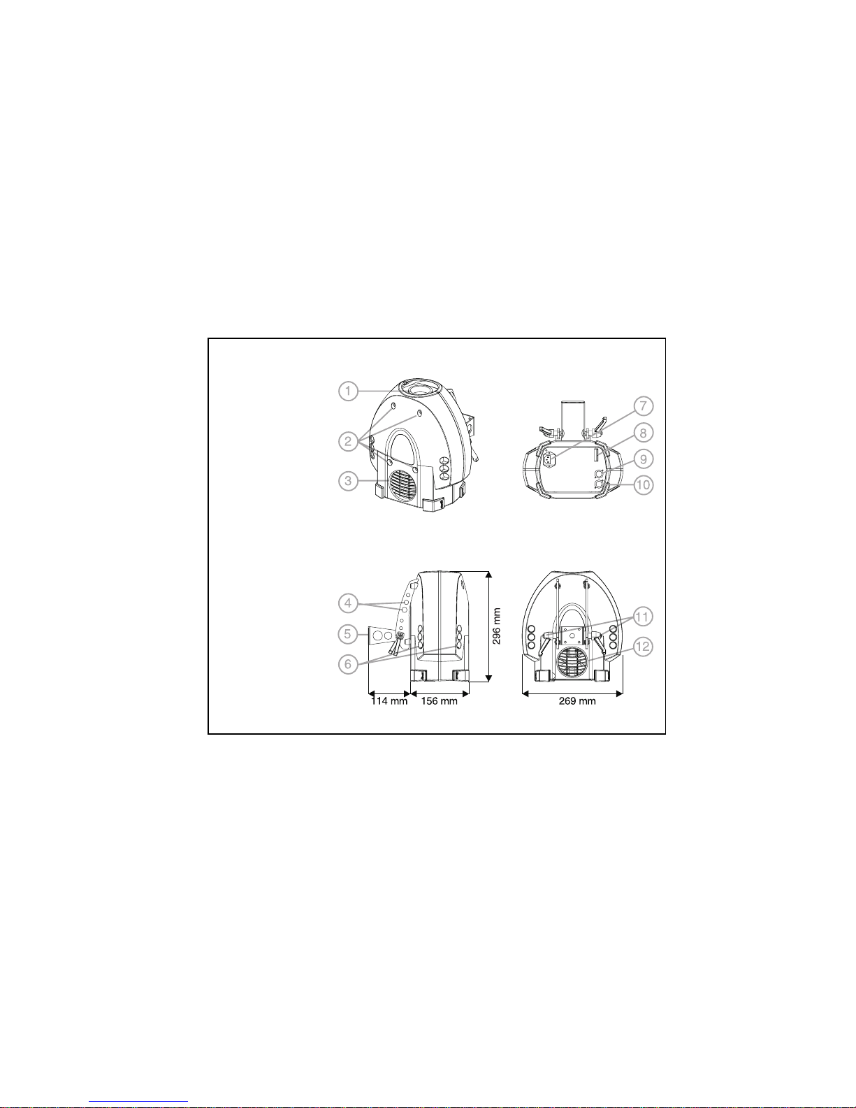
1 focus lens
2 cover locks
3 air vent
4 safety cable holes
5 mounting bracket
6 air vents
7 AC input & main
fuse
8 DIP-switch
9 data output
10 data input
11 swivel locks
12 cooling fan
Page 6
6 Lamp installation CX-2 user manual
L
AMP INSTALLATION
3
The CX-2 uses a 24V, 250W ELC halogen lamp. Two models are available, an
economical 300 hour lamp from Philips and a high-output 50 hour lamp from
Osram. Installing any other lamp may damage the fixture.
Allow the lamp to cool for at least 5 minu tes before packing and moving t he
fixture. To avoid possible damage, remove the lamp when sh ipping the fixture.
To install a lamp in the CX-2
Warning! Always disconnect t he
fixture from AC power
and allow the fixture to
cool for 5 minutes
before installi ng a n ew
lamp.
1 Disconnect the fixture from
AC power. If replacing a hot
lamp, allow it to cool for 5
minutes before removing the
cover. The lamp cools faster
with the cover in place.
2 Release the 4 cover locks by
turning them a quarter-turn
counterclockwise. Lift the cover straight off.
3 To remove the lamp, grasp it by the reflector and pull it out of the holder. Pull
the socket straight back off the metal pins. Do not pull the wires.
4 Push the socket fully onto the pins of the new lamp.
5 Gently push the lamp into the holder until it snaps into place.
6 Replace the top cover. To lock the 4 cover locks, turn them a half to a quarter
turn clockwise until you feel them click.
Do not overtighten
.
Page 7
CX-2 user manual AC power connection 7
AC
POWER CONNECTION
4
Warning! For protection from dangerous electric shock, the fixture must
be grounded (ear thed) . The AC mains supp ly shall have
overload and ground-fault protection.
Important ! Check voltage setting before applying power. Do not connect
the CX-2 to an electrical dimmer system: doing so can damage
the electronics.
Before use verify that the fixture’s power supply is correctly tapped for the local
AC voltage. The default voltage setting is printed on the serial number label near
the AC input. The “EU” version may be set to 230 or 245 V AC and the “US”
version may be set to 110 or 120 V AC. Use the setting that is closest to the local
supply voltage.
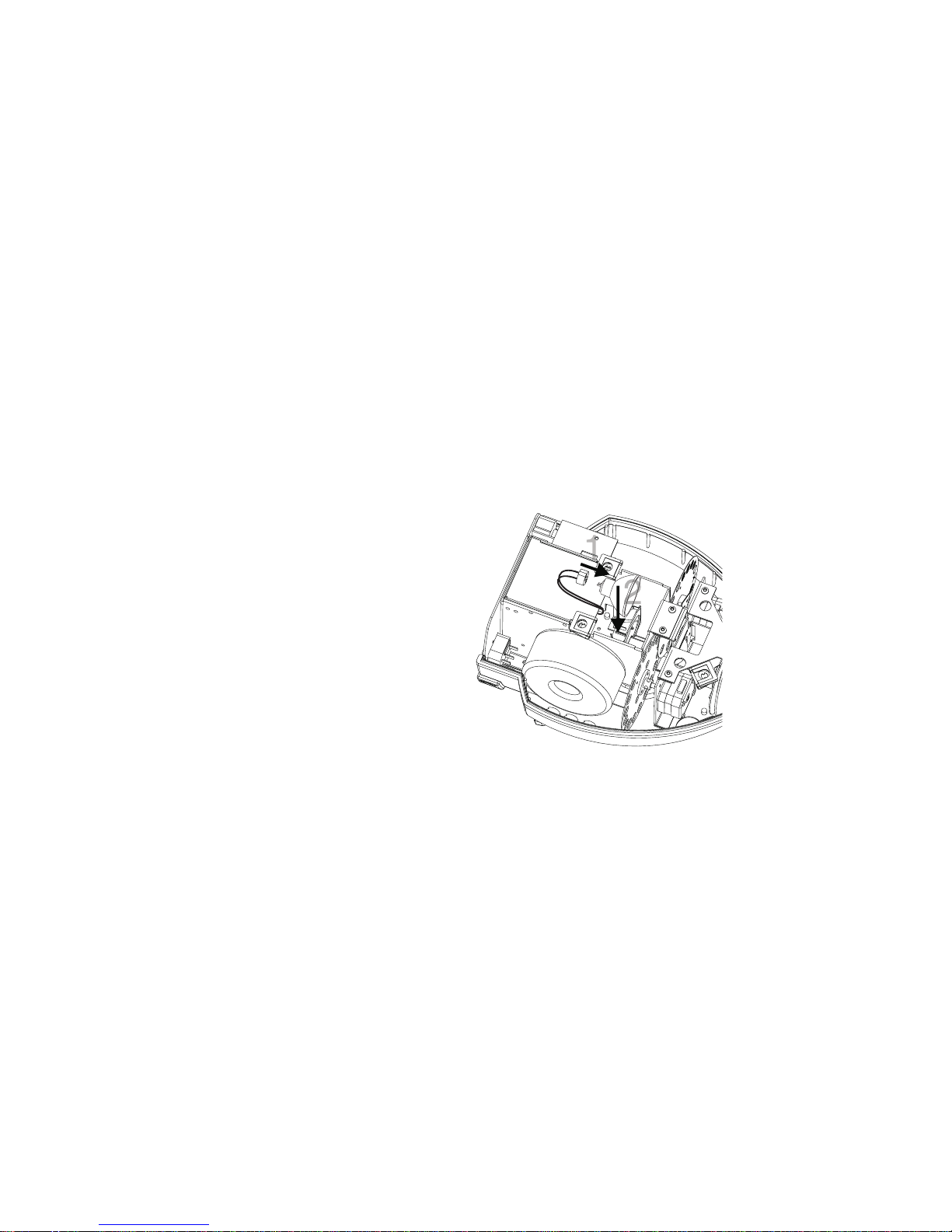
To change the voltage setting
1 Disconnect the fixture from AC power.
Release the 4 cover locks by turning
them a quarter-turn counter clockwi se.
Lift the cover straight off.
2 Locate and disconnect plug PL124 on
the back edge of the printed circuit
board. It has red, yellow, and blue
wires.
3 T o select 230 V AC (EU version) or 110
V AC (US version), flip and move the
plug
up
so that the
red
wire connects
to the
top
pin.
4 T o select 245 V AC (EU version) or 120
V AC (US version), flip and move the
plug
down
so that the
red
wire
connects to the
bottom
pin.
5 Replace the top cover before applying
power.
red
red
Setting for
110 V (US) / 230 V (EU)
Setting for
120 V (US) / 245 V (EU)
Page 8

8 AC power connection CX-2 user manual
To install a plug on the mains lead
The fixture’s mains lead must be fitted with a grounding-type cord cap that
fits your power distribution cable or outlet. Con sult a qual ified electric ian if
you have any doubts about proper installation.
Important! Verify that the feed cables are undamaged and rated for the
current requ iremen ts of all con nected devices b efore use .
• Following the cord cap manufacturer’s instructions, connect the yellow and
green wire to ground (earth), the brown wire to live, and the blue wire to
neutral. The table below shows some pin identification schemes.
Wire Pin Marking Screw color
brown live “L” yellow or brass
blue neutral “N” silver
yellow/green ground green
Page 9

CX-2 user manual Installation 9
I
NSTALLATION
5
The CX-2 can be fastened directly to a suitable surface or to a rigging clamp by
means of its adjustable mounting bracket.
Do not lay the fixture flat on its mounting bracket
arms or position it so that there is less than 10 cm
(4 in.) clearance around the fan and air vents.
For maximum lamp life, do not place the fixture
directly on or beside a speaker cabinet or other
source of strong vibrations.
To rig the CX-2
Warning! Always use a secure means of secondary attachment. Block
access below the work area b efore proceedi ng.
1 Verify that the clamp (not included) is undamaged and can bear at least 10
times the fixture’s weig ht. Bolt the clamp securely to the bracket with a grade
8.8 (minimum) M12 b olt and lock nut, or a s recommen ded by the clamp
manufacturer, through the 13 mm hole in the center of t he mounting bracket.
2 If permanently installing the fixture, verify that the hardware (not included)
and mounting surface can bear at least 10 times the fi xture’s weigh t. The four
6.2 mm holes and/or the 13 mm hole in the mounting bracket may be used.
3 Verify that the structure can support at least 10 times the weight of all
installed fixtures, clamps, cables, auxiliary equipment, etc.
4 Working from a stable platform, clamp or fasten the fixture to the structure.
5 Install a safety cable that can hold at least 10 times the weight of the fixture
through/over the support and through a hole in one of the aluminum arms.
6 Loosen the swivel locks and tilt the fixture to the desired angle. Turn the
swivel locks clockwise to tighten. If a swivel lock does not tighten fully, pull
the handle out, turn it counterclockwise, and retighten. Repeat as necessary.
7 Verify that the fixture is located at least 0.3 meters (12 in.) away from the
surface to be illuminated and at least 0.1 meters (4 in.) from any combustible
materials. Verif y that the clearance around the fan and air vents is at least 0.1
meters (4 in.). Verify that there are no flammable materials nearby.
Page 10

10 DIP-switch settings CX-2 user manual
DIP-
SWITCH SETTINGS
6
This section describes how to select the DMX address and special settings using
the DIP-switch on the end panel.
Important ! Disconnect t he fixt ure from AC power befor e changing the
DIP-switch setting. Changes take effect after the fixture has
been turned off and back on.
DMX ADDRESS SELECTION
If the CX-2 is to be used with a DMX protocol controller, then the DIP-switch
must be set to a D MX control address. The addre ss, also known as the start
channel, is the first channel used to receive instructions from the controller. The
CX-2 uses 4 channels for full DMX operation. For independent control, each
fixture must be assigned its own address and non-overlapping control channels.
Two CX-2s may share the same address only if they are to respo nd ident ically:
they will receive the same inst ruc tio ns and individual control will not be possibl e.
To set the DMX address
1 Select an address for the fixture on your controller.
2 Look up the DIP-switch setting for the address on page 11.
3 Disconnect the fixture from AC power.
4 Set pins 1 through 9 to the ON (1) or OFF (0) position as listed in the table.
5 Set pin 10 to the OFF position.
6 Set pin 11 to the OFF position for full 4-channel DMX operation or to the ON
position for 1-channel DMX operation.
Page 11

CX-2 user manual DIP-switch settings 11
DIP-SWITCH ADDRESS TABLE
Find the address in the table below. Read the settings for pins 1 - 5 to the left and
read the settings for pins 6 - 9 above the add ress. “0 ” m eans OF F and “1 ” m eans
ON.
Importa nt! Pins 10 and 11 must be OFF for full DMX co ntrol. P in 10 must
be OFF and pi n 11 must be ON for 1-chan nel DM X cont rol.
',306ZLWFK#6HWWLQJ
3# #2))
4# #21
&<3333333344444444
&;3333444433334444
&:3344334433443344
&93434343434343434
&4 &5 &6 &7 &8
33333 6597<945;4934<55575895;;6536856;774977;7;3
43333 46698<:45<4944<655858:5;<6546866;874:77<7;4
3 4 3 3 3 5 67 99 <; 463 495 4<7 559 58; 5<3 655 687 6; 9 74; 783 7;5
44333 6689:<<4644964<855:58<5<46566886;:74<7847;6
33433 7699;4334654974<955;5935<56576896;;7537857;7
4 3 4 3 3 8 6: 9< 434 466 498 4<: 55< 594 5<6 658 68: 6; < 754 786 7;8
34433 96;:34354674994<;5635955<765968;6<37557877;9
44433 :6<:443646849:4<<5645965<865:68<6<47567887;:
3 3 3 4 3 ; 73 :5 437 469 49; 533 565 597 5<9 65; 693 6< 5 757 789 7;;
43343 <74:643846:49<5345665985<:65<6946<675878:7;<
34343 4375:743946;4:35355675995<;6636956<775978;7<3
4 4 3 4 3 44 76 :8 43: 46< 4:4 536 568 59: 5<< 664 696 6< 8 75: 78< 7<4
33443 4577:943;4734:553756959;6336656976<975;7937<5
43443 4678::43<4744:653856:59<6346666986<:75<7947<6
3 4 4 4 3 47 79 :; 443 475 4:7 53 9 56; 5:3 635 667 699 6<; 763 795 7<7
44443 487::<4444764:853:56<5:463666869:6<<7647967<8
33334 497;;34454774:953;5735:563766969;7337657977<9
4 3 3 3 4 4: 7< ;4 446 478 4:: 53 < 574 5:6 638 66: 69< 734 766 798 7<:
34334 4;83;54474794:;5435755:763966;6:37357677997<;
44334 4<84;644847:4:<5445765:863:66<6:473676879:7<<
3 3 4 3 4 53 85 ;7 449 47; 4;3 54 5 577 5:9 63; 673 6:5 737 769 79; 833
43434 5486;844:47<4;45465785::63<6746:673876:79<834
34434 5587;944;4834;55475795:;6436756:773976;7:3835
4 4 4 3 4 56 88 ;: 44< 484 4;6 54 8 57: 5:< 644 676 6:8 73: 76< 7:4 836
33344 5789;;4534854;754957;5;36456776:973;7737:5837
43344 588:;<4544864;854:57<5;46466786::73<7747:6838
3 4 3 4 4 59 8; <3 455 487 4;9 54; 583 5;5 647 679 6:; 743 775 7:7 839
44344 5:8<<44564884;:54<5845;664867:6:<7447767:883:
33444 5;93<54574894;;5535855;764967;6;37457777:983;
4 3 4 4 4 5< 94 <6 458 48: 4;< 554 586 5;8 64: 67< 6;4 746 778 7:: 83<
34444 6395<745948;4<35555875;964;6836;57477797:;843
44444 6496<845:48<4<45565885;:64<6846;674877:7:<844
Page 12

12 DIP-switch settings CX-2 user manual
SPECIAL SETTINGS
DIP-switch pins 1 - 9 are used to select special options in stand-alone and
master/slave mode.
To enable these options, pin 10 must be ON.
Pin 11 toggles betw een 1 and 4 channel DMX cont rol. It must be OFF for
master/slave operation.
Lamp life can be extend ed by reducing the voltage slightly. Set DIP-switch pin 12
to ON for longer lamp life, or OFF for full output intensity.
Note: the fixture shall be disconnected from AC power when changing DIP-switch
settings. Changes take effect after the fixture has been turned off.
Important ! Pin 10 must be ON to enable specia l settings on pins 1 - 9.
Pin Setting Effect
1 ON Music trigger
OFF Automatic trigger
2 ON Stand-alone mode on, single or master fixtu re
OFF Stand-alone mode off / slave fixture
3 ON Test program for service use
OFF Normal operation
4 ON Slow color and gobo change
OFF Fast color and gobo change
5 ON No effect
OFF No effect
6 ON Random slave color wheel position (set on slave fixture)
OFF Slave color wheel position same as master
7 ON Random slave gobo wheel position (set on slave fixture)
OFF Slave gobo wheel position same as master
8 ON Invert slave color wheel pos ition (set on slave fixture)
OFF Slave color wheel position same as master
9 ON Invert slave gobo wheel position (set on slave fixture)
OFF Slave gobo wheel position same as master
10 ON Enable special settings with pins 1 - 9
OFF Enable DMX address with pins 1 - 9
11 ON 1-channel mode on
OFF 1-channel mode off
12 ON Reduced power / longer lamp life
OFF Full power / maximum intensity
Page 13

CX-2 user manual Data connection 13
D
ATA CONNECTION
7
This section describes how to connect fixtures to a controller.
RECOMMENDED CABLE
A reliable data connection begins with the right cable. Standar d microphone
cable cannot transmit DMX data reliably over long runs. For best results, use
cable specifically designed for RS-485 applicatio ns. Your Ma rtin dealer can
supply high quality cable in various lengths.
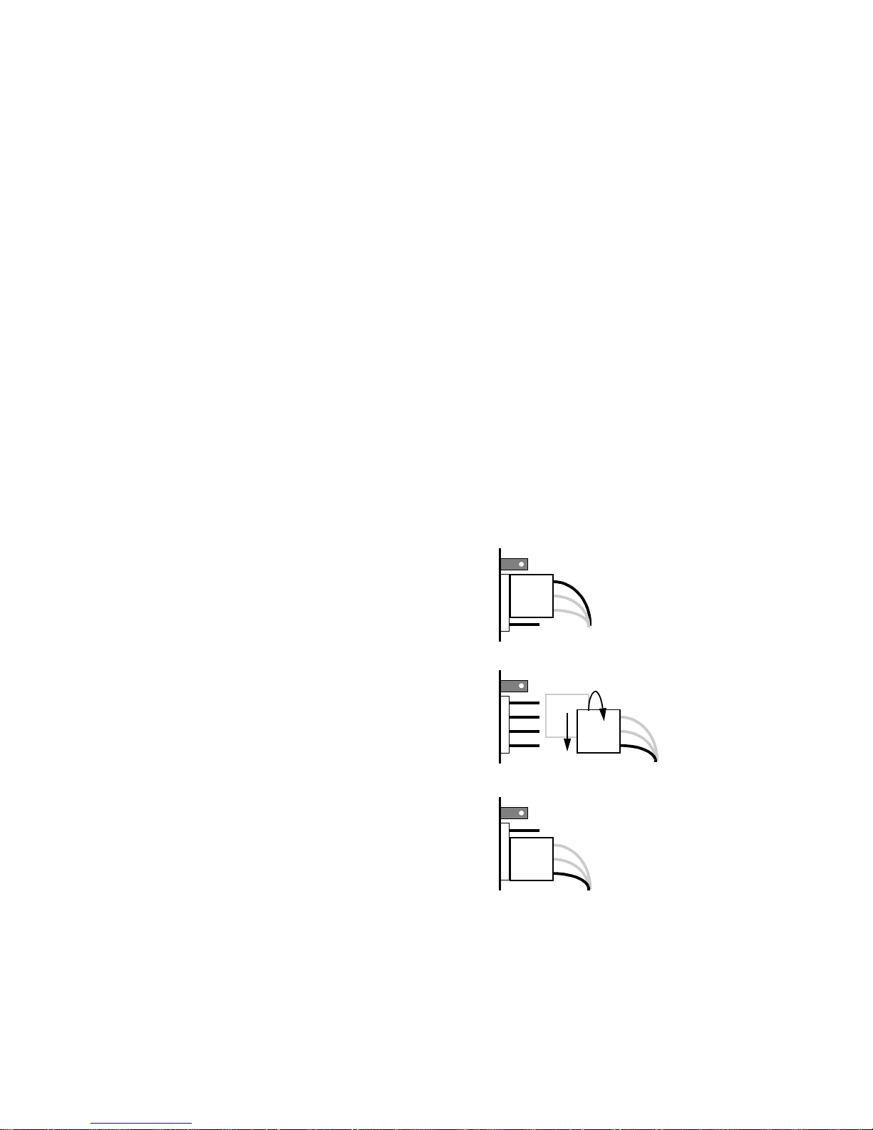
CONNECTIONS
The CX-2’s XLR data sockets are wired with pin 1 to gr ound, pi n 2 to signal -
(cold), and pin 3 to signal + (hot). This is the standard pin assignment for DMX
devices.
One or more adaptor cables may be required to connect the CX-2 to the controller
and/or other lights because many devices have 5-pin connectors and others may
have reversed signal polarity, that is, pin 2 hot and pin 3 cold.
Phase-Reversing
Adaptor
Male Female
1
2
3
1
2
3
3-pin to 3-pin
P/N 11820006
Adaptor
Male Female
1
2
3
4
5
1
2
3
5-pin to 3-pin
P/N 11820005
Adaptor
Male Female
1
2
3
1
2
3
4
5
3-pin to 5-pin
P/N 11820004
Page 14

14 Data connection CX-2 user manual
To connect the data link
1 Connect a data cable to the controller’s data output. If controller has a 5-pin
output, use a 5-pin male to 3-pin fem ale adaptor cable (P/N 11820005).
2 Lead the data cable from the controller to the first fixture. Plug the cable into
the fixture’s data input.
3 Connect the output of the fixture closest to the controller to the input of the
next fixture. If connecting to a fixtu re with reversed-polarity (pin 3 cold),
insert a phase-reversing cable between the two fixtures.
4 Continue connecting fixtures output to input. Up to 32 devices may be
connected on a serial link.
5 Terminate the link by inserting a male termination plug (P/N 91613017) into
the data output of the last fixture. A termination plug is simply an XLR
connector with a 120 ohm, 0.25 W resistor soldered across pins 2 and 3.
Male XLR
1
2
3
Male
P/N 91613017
120
Female XLR
1
2
3
Female
120
Termination PlugTermination Plug
P/N 91613018
Page 15

CX-2 user manual Operatio n 15
O
PERATION
8
FULL DMX OPERATION
For DMX operation, the CX-2 must be connected to a DMX controller as
described under “Data connection” on page 13. DIP-switch pins 1 - 9 must be set
to the DMX address as described on page 10. Pins 10 an d 11 must be set to OFF.
DMX CHANNEL DESCRIPTION
See also the DMX protocol on page 21.
Channel 1 controls the light intensity and the strobe rate. It also allows you to
execute a “stand-alone” program with random color and gobo change using
automatic or music trigger.
All effect wheels are reset to their home position when the fixtur e is powered up;
they can also be reset from the controller by sending a reset command on channel
1.
Channel 2 controls the position of the color wheel. When set to 100 percent, the
wheel moves to random positions using the trigger selected on channel 1.
Channel 3 controls the position of the gobo wheel. When set to 100 pe rcent, the
wheel moves to random positions using the trigger selected on channel 1.
Channel 4 controls the speed of effect wheel rotation, allowing you to vary the
speed on controllers without cross-faders. If your controller has cross-faders, and
you use them, then set channel 4 to t he “t racking” speed (0 percent).
1-CHANNEL DMX OPERATION
The CX-2 may be operated in 1-channel mode with the MC-1 or any DMX
controller. For 1-channel operation, connect the controller as described on page
13.
DIP-switch pin 11 must be set to ON.
If using the MC-1, select DMX channel 1. If using a
DMX controller, any channel within the controller’s
range may be assign e d.
ìíë ê é èì åç æ ä21ìëìì
Page 16

16 Operation CX-2 user manual
The single-channel functions are shown below.
STAND-ALONE OPERATION
The CX-2 automatically operates in stand-alone mode with music trigger if there
is no control signal.
Operation can be modified using the special settings described on page 12. To
enable the special settings, DIP-switch pin 10 must be ON.
Important! The fixture transmits control signals on the data link when
operated in stand-a lone mo de (wi th DIP -switch pin s 2 an d 10
ON). To prevent damage to the electronics , do n ot con nect a
stand-alone fixture to o ther st and-al one fixt ures or to a
controller.
MASTER / SLAVE OPERATION
Multiple CX-2s can be connected together, without a controller, for synchronized
“master/slave” operation in which the slave fixtures mimic the behavior of the
master fixture.
To connect units for master / slave operation
1 Disconnect all fixtures from AC power.
2 Connect the output of one CX-2 to the input of the next CX-2.
3 Connect additional CX-2s output to input. Up to 32 may be connected.
4 Terminate the link on both ends by inserting a female termination plug into
the data input of the first fixture and a male termination plug into the data
output of the last fixture. A termination plug is simply an XLR connector with
a 120 ohm, 0.25 W resistor soldered across pins 2 and 3.
DMX value Percent Function
0 - 10
11 - 20
21 - 80
81 - 115
116 - 140
141 - 175
176 - 210
211 - 255
0 - 4
5 - 7
8 - 31
32 - 45
46 - 55
56 - 68
69 - 82
83 - 100
Blackout (light off)
Open (light on)
Strobe
Random action with slow music trigger
Random action with medium music trigger
Random action with fast music trigger
Random action with random music trigger
Manual trigger area, c rossover at 240 (9 4%)
Page 17

CX-2 user manual Operatio n 17
To set the mast er
Important ! Set only 1 fixt ure a s ma st er (w ith DI P-swi tch pi n 2 a nd 10 ON):
errors and damage can occur if t here is more th an 1 master.
1 Set DIP-switch pins 2 and 10 to ON.
2 Set DIP-switch pins 3, 5, 6, 7, 8, 9, and 11 to OFF.
3 Set DIP-switch pins 1, 4, and 12 ON or OFF, as
desired, to select the options described on page 12.
To set a slave
OPTION 1 (SPECIAL OPTIONS DISABLED)
1 Set DIP-switch pin 1 to ON.
2 Set pins 2 - 11 to OFF.
3 Set pin 12 ON for longer lamp life or OFF for higher
intensity.
OPTION 2 (SPECIAL OPTIONS ENABLED)
1 Set DIP-switch 10 to ON.
2 Set pins 1, 2, 3, 4, 5 and 11 to OFF.
3 Set DIP-switch pins 6, 7, 8, 9, and 12 ON or OFF, as
desired, to select the options described on page 12.
ìíë ê é èì åç æ ä21ìëìì
ìíë ê é èì åç æ ä21ìëìì
ìíë ê é èì åç æ ä21ìëìì
Page 18

18 Basic service CX-2 user manual
B
ASIC SERVICE
9
The CX-2 requires simple routine maintenance. The main tenance schedule
depends heavily on the oper ating environment; ple ase consult a Ma rtin service
technician for recommendations.
Any service procedure not described here should be ref erred to a qualified
technician.
Important ! E xcessi ve dust, greas e, and smoke fluid buildup de grades
performance and causes overheatin g and damage to th e
fixture that is no t covered by the warrant y.
Warning! Disconne ct the fixtur e from AC power before removing a ny
cover.
CLEANING
To clean optical components
Use care when cleaning optical components. The surface of the color filters is
fragile and small scratches may be visible.
1 Disconnect the fixture from AC power and allow the components to cool
completely.
2 Release the 4 cover locks by turning them a quarter-turn counterclockwise.
Lift the cover straight off.
3 Blow or vacuum away loose dust. Rem ove residues from lenses and filters
with a soft clot h or cotton swabs wetted with isopropyl alcohol. Regular glass
cleaner may also be used, but no residues may remain.
4 Rinse with distilled water. Mixing the water with a small amount of wetting
agent such as Kodak Photoflo will help prevent streaking and spot ting.
5 Dry with a clean, soft and lint-free cloth or blow dry with compressed air.
6 Replace the top cover. To lock the 4 cover locks, turn them a half to a quarter
turn clockwise, until you feel them click.
Do not overtighten
.
Page 19

CX-2 user manual Basic service 19
To clean the fan and air vents
To maintain adequate cooling, dust m ust be cleaned from the fan an d air vents
periodically.
1 Remove the data and power cables and stand the fixture on end.
2 Remove dust and dirt from the fan blades and vent grills using a soft brush,
cotton swab, vacuum, or compressed air.
REPLACING FUSES
The CX-2 has 2 fuses. The main fuse holder is built in to the mains input socket.
The secondary fuse is located on the p r in ted circuit board.
Warning! Never replace fuse s with ones o f a dif ferent r ating!
To replace the main fuse
1 Unplug the mains cable from the input socket. Pry open the fuse holder and
remove the fuse.
2 Replace the fuse with one of the same type. The fuse rating is listed on serial
number label.
To replace the secondary fuse
1 Disconnect the fixture from AC power. Release the 4 cover locks by turning
them a quarter-turn counterclockwise. Lift the cover straight off.
2 The fuse is located right behind the data input connector. Pry out the
defective fuse and replace it with one of the same rating.
3 Replace the cover before applying power.
Page 20

20 Troubleshooting CX-2 user manual
T
ROUBLESHOOTING
10
Problem Probable cause(s) Remedy
One or more of the fixtures is
completely dead.
No power to fixture. Check that power is switched on
and cables are plugged in.
Primary fuse blown. Replace fuse.
Secondary fuse blown. Replace fuse.
Fixtures reset correctly but all
respond erratically or not at all
to the controller.
The controller is not connected. Connect controller.
XLR pin-out of the controller
does not match pin-out of the
first fixture on the link (i.e.
signal is reversed).
Install a phase-reversing cable
between the cont roller and the
first fixture on the link.
Fixtures reset correctly but some
respond erratically or not at all
to the controller.
Bad data link connection Inspect connections and cables.
Correct poor connect ions.
Repair or replace damaged
cables.
Data link not terminated with
120Ω
termination plug.
Insert termination plug in output
jack of the last fixture on the
link.
Incorrect addressing of th e
fixtures.
Check DIP-switch settings.
One of the fixtures is
transmitting as a master or is
defective.
Bypass one fixture at a time
until normal operati on i s
regained: unplug both
connectors and connect them
directly togeth e r. Have the
defective fixture serviced by a
qualified technician.
An effect fails to reset correctly. The effect requires m echanical
adjustment.
Contact Martin technician for
service.
No light. Lamp missing or blown Disconnect fixture and rep la ce
lamp.
Lamp cuts out intermittently or
burns out too quickly.
Fixture is too hot. Allow fixture to cool.
The transformer setting does not
match local AC voltage.
Check AC setting.
Page 21

CX-2 user manual DMX protocol 21
DMX
PROTOCOL
A
Channel Value Percent Function
1
0 - 4
5 - 154
155 - 169
170 - 229
230 - 239
240 - 249
250 - 255
0 - 1
2 - 60
61 - 66
67 - 89
90 - 93
94 - 97
98 - 100
Dimmer, Strobe, Reset
Light off
Dimmer, closed to open
Dimmer full open
Strobe, fast to slow
Stand-alone, music trig ger
Stand-alone, auto trigge r
Reset
2
0 - 5
6 - 11
12 - 17
18 - 23
24 - 29
30 - 35
36 - 41
42 - 47
48 - 53
54 - 59
60 - 65
66 - 71
72 - 77
78 - 83
84 - 89
90 - 95
96 - 101
102 - 107
108 - 113
114 - 119
120 - 125
126 - 131
132 - 137
138 - 143
144 - 149
150 - 155
156 - 161
162 - 167
168 - 173
174 - 179
180 - 185
186 - 191
192 - 197
198 - 203
204 - 209
210 - 255
0 - 1
2 - 4
4 - 6
7 - 9
9 - 11
11 - 13
14 - 16
16 - 18
18 - 20
21 - 23
23 - 25
26 - 27
28 - 30
30 - 32
33 - 35
35 - 37
37 - 39
40 - 42
42 - 44
44 - 46
47 - 49
49 - 51
52 - 53
54 - 56
56 - 58
59 - 61
61 - 63
63 - 65
66 - 68
68 - 70
70 - 72
73 - 75
75 - 77
78 - 79
80 - 82
82 - 100
Color Wheel
Open
Open / Light blue 101
Light blue 101
Light blue 101/ Fern green 205
Fern green 205
Fern green 205 / Red 304
Red 304
Red 304 / Yellow 603
Yell ow 603
Yell ow 603 / Magenta 507
Magenta 507
Magenta 507 / Medium blue 108
Medium blue 108
Medium blue 108 / Deep orange 302
Deep orange 302
Deep orange 302 / Light green 204
Light green 204
Light green 204 / Cyan 1 04
Cyan 104
Cyan 104 / Pink 312
Pink 312
Pink 312 / Blue 111
Blue 111
Blue 111 / Amber 604
Amber 604
Amber 604 / Primary red 308
Primary red 308
Primary red 308 / Primary green 206
Primary green 206
Primary green 206 / Orange 306
Orange 306
Orange 306 / Split-color 1
Split-color 1
Split-color 1 / Split-color 2
Split-color 2
Random “stand-alone ” position w/ music or auto trigger
Page 22

22 DMX protocol CX-2 user manual
2
0 - 11
12 - 23
24 - 35
36 - 47
48 - 59
60 - 71
72 - 83
84 - 95
96 - 107
108 - 119
120 - 131
132 - 143
144 - 155
156 - 167
168 - 179
180 - 191
192 - 203
204 - 215
216 - 255
0 - 4
5 - 8
9 - 13
14 - 18
19 - 23
24 - 27
28 - 32
33 - 37
38 - 41
42 - 46
47 - 51
52 - 55
56 - 60
61 - 65
66 - 70
71 - 74
75 - 79
80 - 84
85 - 100
Gobo Wheel
Open
Frost
Virus
Dot circle
Spokes
Atomic
Dot cross
Dot cone
Holes 3
Clouds 2
Highways
Worms 3
XL iris
L iris
M iris
S iris
XS iris
Closed
Random “stand-alo ne” posi ti on w/ music or auto trigger
4
0 - 2
3 - 255
0 - 1
2 - 100
Color / Gobo Speed
Tracking (speed function off)
Fast to slow
Channel Value Percent Function
Page 23

S
PECIFICATIONS
B
PHYSICAL
Size (L x W x H): . . . . . . . . . . . . . . . . . . . . . . . 296 x 269 x 270 mm (11.7 x 10.6 x 12.1 in)
Weight: . . . . . . . . . . . . . . . . . . . . . . . . . . . . . . . . . . . . . . . . . . . . . . . . . . . . .5.5 kg (12.1 lbs)
THERMAL
Maximum ambient temperature (Ta): . . . . . . . . . . . . . . . . . . . . . . . . . . . . . . . 40° C (104° F)
Maximum surface temperature: . . . . . . . . . . . . . . . . . . . . . . . . . . . . . . . . . . .65° C (149° F )
CONTROL AND PROGRAMMING
DMX-512 (1990) control: . . . . . . . . . . . . . . . . . . . . . . . . 1 / 4 channe l, track ing and vector
Stand-alone contro l: . . . . . . . . . . . . . automatic & music trigger, master/slave configurable
Data pinout: . . . . . . . . . . . . . . . . . . . .3-pin XLR - pin 1 shie ld, pin 2 cold (-), pin 3 hot (+)
AC SUPPLY
AC input: . . . . . . . . . . . . . . . . . . . . . . . . . . . . . . . . . . . . . . . . . . . . . .3-pin IEC mal e socket
Wiring options, "EU" model: . . . . . . . . . . . . . . . . . . . . . . . . . . . . . . . . 230/245 V, 50-60 Hz
Wiring options, "US" model: . . . . . . . . . . . . . . . . . . . . . . . . . . . . . . . . 110/120 V, 50-60 Hz
Maximum power and current: . . . . . . . . . . . . . . . . . . . . . . . . . . . . . 250 W, 1.1 A @ 230 V
FUSES
Primary fuse, EU model: . . . . . . . . . . . . . . . . . . . . . . . . . . . 2.5 AT / 250 V, P/N 05020010
Primary fuse, US model: . . . . . . . . . . . . . . . . . . . . . . . . . . . 5.0 AT / 250 V, P/N 05020018
Secondary fuse: . . . . . . . . . . . . . . . . . . . . . . . . . . . . . . . . . . 2.0 AT / 250 V, P/N 05020009
CONSTRUCTION
Housing: . . . . . . . . . . . . . . . . . . . . . . . . . . . . . . . . . UV- resi s ta nt fiber-reinforced composite
Finish: . . . . . . . . . . . . . . . . . . . . . . . . . . . . . . . . . . . . . . . . . . . . . . . . . . . black, integral color
INSTALLATION
Minimum distance to combustible materials: . . . . . . . . . . . . . . . . . . . . . . . . . . 0.1 m (4 in)
Minimum distance to illuminated surfaces: . . . . . . . . . . . . . . . . . . . . . . . . . . . 0.3 m (12 in)
Minimum clearance a round fan and air vents: . . . . . . . . . . . . . . . . . . . . . . . . . . 0.1 m (4 in)
ACCESSORIES
MC-1 Controller, EU: . . . . . . . . . . . . . . . . . . . . . . . . . . . . . . . . . . . . . . . . . . . . . . .90718000
MC-1 Controller, US: . . . . . . . . . . . . . . . . . . . . . . . . . . . . . . . . . . . . . . . . . . . . . . . 90718100
OSRAM 50 h ELC halogen lamp: . . . . . . . . . . . . . . . . . . . . . . . . . . . . . . . . . . . . . 97000104
Philips 300 h ELC halog en lamp: . . . . . . . . . . . . . . . . . . . . . . . . . . . . . . . . . . . . . 97000106
G-clamp: . . . . . . . . . . . . . . . . . . . . . . . . . . . . . . . . . . . . . . . . . . . . . . . . . . . . . . . . . 91602003
Half-coupler clamp: . . . . . . . . . . . . . . . . . . . . . . . . . . . . . . . . . . . . . . . . . . . . . . . . 91602005
Page 24

58 83 :8 433 458 483 4:8 533 558 583
*5IURVW
RSHQ
58 83 :8 433 458 483 4:8 533 558 583
%22
fast slow
DXWR
CX-2 4-Channel DMX Proto c ol
#6WUREH'LPPHU
*9*8
*6
V#LULV
6WDQG0DORQH
43 53 63 73 83 93 :3 ;3 <3
58 83 :8 433 458 483 4:8 533 558 583
43 53 63 73 83 93 :3 ;3 <3
&RORU2JRER#VSHHG
VORZ
43 53 63 73 83 93 :3 ;3 <3
58 83 :8 433 458 483 4:8 533 558 583
%22
0XVLF#WULJJHU
CX-2 1-Channel DMX Protocol
#5
#4
#6
#7
6WDQG0DORQH
PXVLF
RSHQFORVHG
*4 *7 *: *; *< *43 [O#LULV O#LULV P#LULV
[V#LULV FORVHG
fast slow
/LJKW#
RQ
6WUREH
PHGLXP IDV W
0DQXDO#WULJJHU#DUHD
RSHQ
5
H
V
H
W
*RER2(IIHFW#ZKHHO
R
I
I
UDQGRP
0DUWLQ#3URIHVVLRQDO#$26
Olof Palmes Allé 18 8200 Aarhus N Denmark Tel.: +45 8740 0000 Fax: +45 8740 0010 Internet: www.martin.dk
2
R
S
H
Q
6WDQG0DORQH
&RORU#ZKHHO
&4 2 &5 2 &6 2 &7 2 &8 2 &9 2 &: 2 &; 2 &< 2
&432&44
2
&452&462&472&4826&426&5
 Loading...